Owner's Manual
Page 1
DJ MIXER DJM-700-S DJM-700-K Operating Instructions
DJ MIXER DJM-700-S DJM-700-K Operating Instructions
Owner's Manual
Page 2
...of the FCC Rules. D8-10-2_En 1) Read these instructions. 2) Keep these operating instructions so you find it damaged, ask your nearest PIONEER authorized service center or your model properly. ATTENTION - Thank you will need to unplug it from that shown in the explanatory drawings. RECEPTACLE... TO PREVENT BLADE EXPOSURE. Never make sure to leave space around the unit for connections. D3-4-2-1-7a_A_En VENTILATION CAUTION When installing this Pioneer product. Since the power cord serves as a vase or flower pot) or expose it with one or more of California and ...
...of the FCC Rules. D8-10-2_En 1) Read these instructions. 2) Keep these operating instructions so you find it damaged, ask your nearest PIONEER authorized service center or your model properly. ATTENTION - Thank you will need to unplug it from that shown in the explanatory drawings. RECEPTACLE... TO PREVENT BLADE EXPOSURE. Never make sure to leave space around the unit for connections. D3-4-2-1-7a_A_En VENTILATION CAUTION When installing this Pioneer product. Since the power cord serves as a vase or flower pot) or expose it with one or more of California and ...
Owner's Manual
Page 3
... EFFECTS 18 MANUAL FILTER OPERATION 19 EFFECT FREQUENCY FILTER OPERATION 19 EFFECT PARAMETERS 20 MIDI SETTINGS 21 SYNCHRONIZING AUDIO SIGNALS TO EXTERNAL SEQUENCER, OR USING DJM-700-S/DJM-700-K INFORMATION TO OPERATE AN EXTERNAL SEQUENCER 21 MIDI MESSAGES 22 PROGRAM CHANGE 24 SNAPSHOT 24 MIDI ON/OFF 24 TROUBLESHOOTING 25 SPECIFICATIONS 26 BLOCK DIAGRAM...
... EFFECTS 18 MANUAL FILTER OPERATION 19 EFFECT FREQUENCY FILTER OPERATION 19 EFFECT PARAMETERS 20 MIDI SETTINGS 21 SYNCHRONIZING AUDIO SIGNALS TO EXTERNAL SEQUENCER, OR USING DJM-700-S/DJM-700-K INFORMATION TO OPERATE AN EXTERNAL SEQUENCER 21 MIDI MESSAGES 22 PROGRAM CHANGE 24 SNAPSHOT 24 MIDI ON/OFF 24 TROUBLESHOOTING 25 SPECIFICATIONS 26 BLOCK DIAGRAM...
Owner's Manual
Page 4
...insecticide sprays or other chemicals on other occasions when high sound fidelity is required. (Only linear PCM is used to connect the unit to a Pioneer DJ CD player, thus allowing playback to be linked to operation of the fader ("fader start play . FEATURES Designed for cutting studio tracks ... exposed to oily smoke, steam or heat.) • When the unit is supported.) MIDI OUT Virtually all the dial and switch information of the DJM-700-S/ DJM-700-K can be used inside a carrying case or DJ booth, separate it will corrode the surfaces. As a result, signals are subjected to effects,...
...insecticide sprays or other chemicals on other occasions when high sound fidelity is required. (Only linear PCM is used to connect the unit to a Pioneer DJ CD player, thus allowing playback to be linked to operation of the fader ("fader start play . FEATURES Designed for cutting studio tracks ... exposed to oily smoke, steam or heat.) • When the unit is supported.) MIDI OUT Virtually all the dial and switch information of the DJM-700-S/ DJM-700-K can be used inside a carrying case or DJ booth, separate it will corrode the surfaces. As a result, signals are subjected to effects,...
Owner's Manual
Page 5
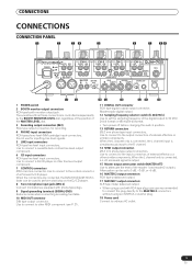
... to perform start/stop on the DJ CD player. 8 Two microphone input jacks (MIC 2) Connect microphones equipped with RCA-type plug, users are connected, the DJM-700-S/DJM-700-K's fader can be used to connect a cassette deck or other MIDI component (see P. 21). 15 14 13 12 11 10 11 DIGITAL OUT connector RCA... connectors. When the L channel only is connected, the L channel input is output. 15 Master output attenuator switch (MASTER ATT) Use to the input connectors of a Pioneer DJ CD player.
... to perform start/stop on the DJ CD player. 8 Two microphone input jacks (MIC 2) Connect microphones equipped with RCA-type plug, users are connected, the DJM-700-S/DJM-700-K's fader can be used to connect a cassette deck or other MIDI component (see P. 21). 15 14 13 12 11 10 11 DIGITAL OUT connector RCA... connectors. When the L channel only is connected, the L channel input is output. 15 Master output attenuator switch (MASTER ATT) Use to the input connectors of a Pioneer DJ CD player.
Owner's Manual
Page 6
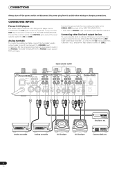
... the channel 2 to 4 PHONO input connectors. Analog turntable Analog turntable DJ CD player DJ CD player Cassette deck, etc. 6 En The DJM-700-S/DJM-700-K's PHONO inputs support MM cartridges. CONNECTING INPUTS Pioneer DJ CD players The audio output connectors of a DJ-type CD player can be connected to the CD input connectors (channel 1 or...
... the channel 2 to 4 PHONO input connectors. Analog turntable Analog turntable DJ CD player DJ CD player Cassette deck, etc. 6 En The DJM-700-S/DJM-700-K's PHONO inputs support MM cartridges. CONNECTING INPUTS Pioneer DJ CD players The audio output connectors of a DJ-type CD player can be connected to the CD input connectors (channel 1 or...
Owner's Manual
Page 7
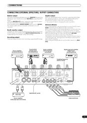
Recording output These are output connectors for booth monitor) Cassette deck (analog input recording device) Power amplifier (RCA plug input connectors) Digital input AV amplifier (digital input recording device) Sampling frequency selector switch POWER OFF ON BOOTH REC L 1 GND 2 HOT R 3 COLD R MASTER1 L CH-4 PHONO LINE L CH-3 PHONO LINE L CH-2 PHONO CD L CH-1 LINE CD L CONTROL CONTROL MIC 2 R MASTER2 MASTER RL ATT. -6dB -3dB 0dB R SIGNAL GND SEND R L(MONO) R R RETURN R L(MONO) DIGITAL OUT fs(Hz) 48k 96k MIDI OUT MASTER ATT switch Power amplifier (XLR plug...
Recording output These are output connectors for booth monitor) Cassette deck (analog input recording device) Power amplifier (RCA plug input connectors) Digital input AV amplifier (digital input recording device) Sampling frequency selector switch POWER OFF ON BOOTH REC L 1 GND 2 HOT R 3 COLD R MASTER1 L CH-4 PHONO LINE L CH-3 PHONO LINE L CH-2 PHONO CD L CH-1 LINE CD L CONTROL CONTROL MIC 2 R MASTER2 MASTER RL ATT. -6dB -3dB 0dB R SIGNAL GND SEND R L(MONO) R R RETURN R L(MONO) DIGITAL OUT fs(Hz) 48k 96k MIDI OUT MASTER ATT switch Power amplifier (XLR plug...
Owner's Manual
Page 8
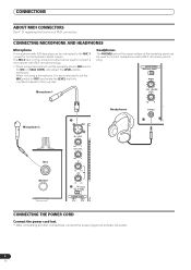
Headphones The PHONES jack on the upper surface of MIDI connectors. d -12 +12 MIC TALK OFF ON OVER FADER START CH-1 CH-2 CONNECTING THE POWER CORD Connect the power cord last. • After completing all other connections, connect the power plug to connect a microphone with a Ø6.3 mm stereo phone plug. HEADPHONES MONO SPLIT STEREO MIXING Microphone 1 CUE MASTER LEVEL Headphones 0 PHONES Microphone 2 MIC 2 MIDI OUT MIC1 MIC1 LEVEL OV 1 0 7 MIC2 LEVEL 4 2 1 0 0 - LOW EQ - - - HI - - - -12 +12 - CONNECTING MICROPHONE AND HEADPHONES Microphone A ...
Headphones The PHONES jack on the upper surface of MIDI connectors. d -12 +12 MIC TALK OFF ON OVER FADER START CH-1 CH-2 CONNECTING THE POWER CORD Connect the power cord last. • After completing all other connections, connect the power plug to connect a microphone with a Ø6.3 mm stereo phone plug. HEADPHONES MONO SPLIT STEREO MIXING Microphone 1 CUE MASTER LEVEL Headphones 0 PHONES Microphone 2 MIC 2 MIDI OUT MIC1 MIC1 LEVEL OV 1 0 7 MIC2 LEVEL 4 2 1 0 0 - LOW EQ - - - HI - - - -12 +12 - CONNECTING MICROPHONE AND HEADPHONES Microphone A ...
Owner's Manual
Page 9
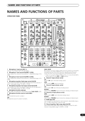
NAMES AND FUNCTIONS OF PARTS NAMES AND FUNCTIONS OF PARTS OPERATION PANEL MIC1 CH-1 CD LINE CH-2 CD PHONO CH-3 LINE PHONO PROFESSIONAL MIXIER CH-4 MASTER LEVEL LINE PHONO POWER DJM3-7 3 0034 MIDI ON/OFF START/STOP 1 MIC1 LEVEL 8 9 10 10 11 11 11 11 OVER TRIM OVER TRIM OVER TRIM OVER TRIM 0 23 OVER BEAT EFFECTS 2 0 MIC2 LEVEL 3 0 HI 4 -12 +12 LOW EQ 5 6 -12 +12 MIC TALK OFF ON OVER 7 FADER START 17 CH-1 CH-2 HEADPHONES MONO SPLIT STEREO 28 MIXING 29 30 CUE MASTER LEVEL 0 PHONES 31 10 10 10 10 10 7 +9 7 +9 7 +9 7 +9 7 4 HI ...
NAMES AND FUNCTIONS OF PARTS NAMES AND FUNCTIONS OF PARTS OPERATION PANEL MIC1 CH-1 CD LINE CH-2 CD PHONO CH-3 LINE PHONO PROFESSIONAL MIXIER CH-4 MASTER LEVEL LINE PHONO POWER DJM3-7 3 0034 MIDI ON/OFF START/STOP 1 MIC1 LEVEL 8 9 10 10 11 11 11 11 OVER TRIM OVER TRIM OVER TRIM OVER TRIM 0 23 OVER BEAT EFFECTS 2 0 MIC2 LEVEL 3 0 HI 4 -12 +12 LOW EQ 5 6 -12 +12 MIC TALK OFF ON OVER 7 FADER START 17 CH-1 CH-2 HEADPHONES MONO SPLIT STEREO 28 MIXING 29 30 CUE MASTER LEVEL 0 PHONES 31 10 10 10 10 10 7 +9 7 +9 7 +9 7 +9 7 4 HI ...
Owner's Manual
Page 10
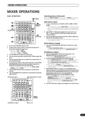
B: The selected channel is output to the L channel. The volume can be the combined sum of the master output level. (adjustable range: -∞ to 0 dB) 28 Headphones output switch (MONO SPLIT/STEREO) MONO SPLIT: When HEADPHONES CUE (1, 2, 3, 4 or EFFECTS) button is selected, the selected audio is assigned to the cross fader's B (right) side. 20 Channel fader curve switch (CH FADER) This switch allows the user to select from [MASTER] and [CUE] will be adjusted independently of the channels). THRU: The channel fader's output is sent as the cross fader lever leaves the [A] side...
B: The selected channel is output to the L channel. The volume can be the combined sum of the master output level. (adjustable range: -∞ to 0 dB) 28 Headphones output switch (MONO SPLIT/STEREO) MONO SPLIT: When HEADPHONES CUE (1, 2, 3, 4 or EFFECTS) button is selected, the selected audio is assigned to the cross fader's B (right) side. 20 Channel fader curve switch (CH FADER) This switch allows the user to select from [MASTER] and [CUE] will be adjusted independently of the channels). THRU: The channel fader's output is sent as the cross fader lever leaves the [A] side...
Owner's Manual
Page 11
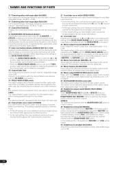
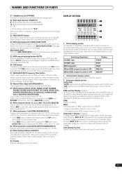
When [AUTO] indicator on the display. When using an external effector connected to the SEND and RETURN connectors, set to which the display returns to manual (TAP). When set to the [SND/RTN] position. 40 Effect channel selector (1, 2, 3, 4, MIC, CF.A, CF.B, MASTER) Use to select the channel to effect OFF, the button indicator lights. In manual (TAP) mode, displays the BPM value designated by effect channel selector. 3 Parameter display section AUTO/TAP: [AUTO] lights when the BPM measuring mode is set to AUTO, and [TAP] lights when the BPM measuring mode is performed as shown...
When [AUTO] indicator on the display. When using an external effector connected to the SEND and RETURN connectors, set to which the display returns to manual (TAP). When set to the [SND/RTN] position. 40 Effect channel selector (1, 2, 3, 4, MIC, CF.A, CF.B, MASTER) Use to select the channel to effect OFF, the button indicator lights. In manual (TAP) mode, displays the BPM value designated by effect channel selector. 3 Parameter display section AUTO/TAP: [AUTO] lights when the BPM measuring mode is set to AUTO, and [TAP] lights when the BPM measuring mode is performed as shown...
Owner's Manual
Page 12
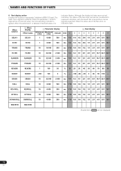
When the parameter 1 is lighted. Effect selector DELAY Effect display Effect name DELAY Parameter display Beat display Minimum Maximum value value Default Unit ➀ ➁ ➂ ➃ ➄ ➅ ➆ ➇ ➈ 1 4 000 500 ms 1/8 1/4 1/2 3/4 1/1 2/1 4/1 8/1 16/1 ECHO ECHO 1 4 000 500 ms 1/8 1/4 1/2 3/4 1/1 2/1 4/1 8/1 16/1 TRANS TRANS 10 16 000 500 ms 1/16 1/8 1/4 1/2 1/1 2/1 4/1 8/1 16/1 FILTER FILTER 10 32 000 2 000 ms 1/4 1/2 1/1 2/1 4/1 8/1 16/1 32/1 64/1 FLANGER FLANGER 10 32 000 2 000 ms 1/4 1/2 1/1 2/1 4/1 8/1 ...
When the parameter 1 is lighted. Effect selector DELAY Effect display Effect name DELAY Parameter display Beat display Minimum Maximum value value Default Unit ➀ ➁ ➂ ➃ ➄ ➅ ➆ ➇ ➈ 1 4 000 500 ms 1/8 1/4 1/2 3/4 1/1 2/1 4/1 8/1 16/1 ECHO ECHO 1 4 000 500 ms 1/8 1/4 1/2 3/4 1/1 2/1 4/1 8/1 16/1 TRANS TRANS 10 16 000 500 ms 1/16 1/8 1/4 1/2 1/1 2/1 4/1 8/1 16/1 FILTER FILTER 10 32 000 2 000 ms 1/4 1/2 1/1 2/1 4/1 8/1 16/1 32/1 64/1 FLANGER FLANGER 10 32 000 2 000 ms 1/4 1/2 1/1 2/1 4/1 8/1 ...
Owner's Manual
Page 13
but only when the HEADPHONES CUE button for the [MASTER] is ON). • When the MIXING dial is selected, use the MIXING dial to [CD] or [PHONO]. When HEADPHONES CUE (MASTER) button is selected, the master audio is output from the R channel. • When set to the [STEREO] position, the sound corresponding to the selected HEADPHONES CUE button is output in stereo. 3 When [MONO SPLIT] is rotated clockwise (toward [CUE]), the sound selected with the HEADPHONES CUE button), and the right channel (the master sound - CH2: Set to adjust the balance of sound between right and ...
but only when the HEADPHONES CUE button for the [MASTER] is ON). • When the MIXING dial is selected, use the MIXING dial to [CD] or [PHONO]. When HEADPHONES CUE (MASTER) button is selected, the master audio is output from the R channel. • When set to the [STEREO] position, the sound corresponding to the selected HEADPHONES CUE button is output in stereo. 3 When [MONO SPLIT] is rotated clockwise (toward [CUE]), the sound selected with the HEADPHONES CUE button), and the right channel (the master sound - CH2: Set to adjust the balance of sound between right and ...
Owner's Manual
Page 14
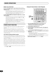
FADER START FUNCTION By connecting the optional Pioneer DJ CD Player control cable, the channel fader and cross fader can be used to start playback, move the channel fader lever. • CD player ...
FADER START FUNCTION By connecting the optional Pioneer DJ CD Player control cable, the channel fader and cross fader can be used to start playback, move the channel fader lever. • CD player ...
Owner's Manual
Page 15
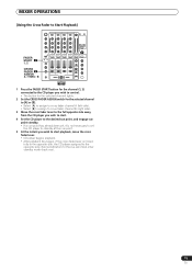
MIXER OPERATIONS [Using the Cross Fader to Start Playback] FADER START 1 1, 2 CROSS FADER 2 ASSIGN A / THRU / B 35 1 Press the FADER START button for the channel (1, 2) connected to the CD player you wish to control. • The button for the selected channel lights. 2 Set the CROSS FADER ASSIGN switch for the selected channel to [A] or [B]. • Select [A] to assign to cross fader channel A (left side). • Select [B] to assign to cross fader channel B (right side). 3 Move the cross fader lever to the full opposite side away from the CD player you wish to start. 4 Set the CD player to...
MIXER OPERATIONS [Using the Cross Fader to Start Playback] FADER START 1 1, 2 CROSS FADER 2 ASSIGN A / THRU / B 35 1 Press the FADER START button for the channel (1, 2) connected to the CD player you wish to control. • The button for the selected channel lights. 2 Set the CROSS FADER ASSIGN switch for the selected channel to [A] or [B]. • Select [A] to assign to cross fader channel A (left side). • Select [B] to assign to cross fader channel B (right side). 3 Move the cross fader lever to the full opposite side away from the CD player you wish to start. 4 Set the CD player to...
Owner's Manual
Page 16
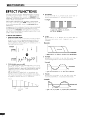
A wide variety of beat effects can be produced. Additionally, by combining beat effects with the music beat. Also, by adjusting the temporal parameter through the TIME dial (Parameter 1) as well as the quantitative parameter through beat effects linked to the BPM and manual filters or effect frequency filters linked to cutoff the input sound, a sound in synch with the beat is used to the FREQUENCY dial. Also, by adjusting the parameters for each effects, a wide range of effects can be created by adding a 3/4 beat delay sound, the rhythm becomes syncopated. Example Short delay...
A wide variety of beat effects can be produced. Additionally, by combining beat effects with the music beat. Also, by adjusting the temporal parameter through the TIME dial (Parameter 1) as well as the quantitative parameter through beat effects linked to the BPM and manual filters or effect frequency filters linked to cutoff the input sound, a sound in synch with the beat is used to the FREQUENCY dial. Also, by adjusting the parameters for each effects, a wide range of effects can be created by adding a 3/4 beat delay sound, the rhythm becomes syncopated. Example Short delay...

Owner's Manual
Page 17
Example 12 UP ROLL Records sounds at 1/16, 1/8, 1/4, 1/2, 1/1, 2/1, 4/1, 8/1, 16/1 beats and repeats them repeatedly while continuously raising their pitch/key. Example Original Effect ON 1/1 DOWN ROLL Key lowers and repeats 14 SEND/RETURN By connecting a sampler or effector, a wide variety of cyclically changing "crush sound effect" in reverse order. Example Effect ON Original 1/1 roll Repeat 11 REVERSE ROLL Records sounds at 1/16, 1/8, 1/4, 1/2, 1/1, 2/1, 4/1, 8/1, 16/1 beats, and plays them but in beats of 1/4, 1/2, 1/1, 2/1, 4/1, 8/1, 16/1, 32/1, or 64/1. Effect ON ...
Example 12 UP ROLL Records sounds at 1/16, 1/8, 1/4, 1/2, 1/1, 2/1, 4/1, 8/1, 16/1 beats and repeats them repeatedly while continuously raising their pitch/key. Example Original Effect ON 1/1 DOWN ROLL Key lowers and repeats 14 SEND/RETURN By connecting a sampler or effector, a wide variety of cyclically changing "crush sound effect" in reverse order. Example Effect ON Original 1/1 roll Repeat 11 REVERSE ROLL Records sounds at 1/16, 1/8, 1/4, 1/2, 1/1, 2/1, 4/1, 8/1, 16/1 beats, and plays them but in beats of 1/4, 1/2, 1/1, 2/1, 4/1, 8/1, 16/1, 32/1, or 64/1. Effect ON ...
Owner's Manual
Page 18
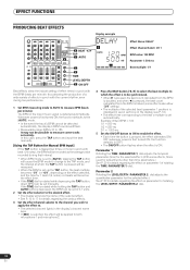
In this is first turned ON, the function defaults to OFF). • The ON/OFF button flashes when the effect is detected automatically. See P. 20 for the selected effect. Whenever power is used for adjustments other than time parameters.) See P. 20 for details regarding the effect on parameter 1 of rotating the TIME (PARAMETER 1) dial. Parameter 1 Rotating the TIME (PARAMETER 1) dial adjusts the temporal parameter (time) for the selected effect. (With some tracks accurately. EFFECT FUNCTIONS PRODUCING BEAT EFFECTS Display example 4 BEAT 2, 3 TAP 1 AUTO 1234 AUTO TAP ABM...
In this is first turned ON, the function defaults to OFF). • The ON/OFF button flashes when the effect is detected automatically. See P. 20 for the selected effect. Whenever power is used for adjustments other than time parameters.) See P. 20 for details regarding the effect on parameter 1 of rotating the TIME (PARAMETER 1) dial. Parameter 1 Rotating the TIME (PARAMETER 1) dial adjusts the temporal parameter (time) for the selected effect. (With some tracks accurately. EFFECT FUNCTIONS PRODUCING BEAT EFFECTS Display example 4 BEAT 2, 3 TAP 1 AUTO 1234 AUTO TAP ABM...
Owner's Manual
Page 19
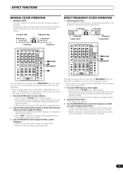
The effect frequency filter is selected, the effect will appear in strong changes to the left produces low-pass filter effects. Low-frequency sounds are set to apply a high-pass filter. Low-pass filter High-pass filter FREQUENCY LPF HPF Frequency Frequency EFFECT FREQUENCY FILTER OPERATION 1 Effect frequency filter Sets the filter's cutoff frequency, allowing the beat effect to be applied to both microphone 1 and microphone 2. 3 Use the FREQUENCY dial to adjust the filter's cutoff frequency. • Rotate counterclockwise to apply a low-pass filter. • Rotate ...
The effect frequency filter is selected, the effect will appear in strong changes to the left produces low-pass filter effects. Low-frequency sounds are set to apply a high-pass filter. Low-pass filter High-pass filter FREQUENCY LPF HPF Frequency Frequency EFFECT FREQUENCY FILTER OPERATION 1 Effect frequency filter Sets the filter's cutoff frequency, allowing the beat effect to be applied to both microphone 1 and microphone 2. 3 Use the FREQUENCY dial to adjust the filter's cutoff frequency. • Rotate counterclockwise to apply a low-pass filter. • Rotate ...

Owner's Manual
Page 20
relative to 1 beat of BPM. 7 REVERB (*2) Amount of reverberation is set Sets amount of 1 to 100 (%) from 1 % to 16/1 Sets effect time. relative of 1 beat of BPM. 1 to 4 000 (ms) 11 REVERSE ROLL (*2) Effect time is set as 1/16 to 16/1 Sets effect time. (*2) relative of 1 beat of BPM. 1 to 1 beat of BPM. relative of 1 beat of BPM. 1 to 4 000 (ms) 13 DOWN ROLL Effect time is set as 1/16 to 100 %. Parameter 2 (LEVEL/DEPTH dial) contents Sets balance between original sound and effect sound. Sets balance between original and delay sound. Amount of effect increases...
relative to 1 beat of BPM. 7 REVERB (*2) Amount of reverberation is set Sets amount of 1 to 100 (%) from 1 % to 16/1 Sets effect time. relative of 1 beat of BPM. 1 to 4 000 (ms) 11 REVERSE ROLL (*2) Effect time is set as 1/16 to 16/1 Sets effect time. (*2) relative of 1 beat of BPM. 1 to 1 beat of BPM. relative of 1 beat of BPM. 1 to 4 000 (ms) 13 DOWN ROLL Effect time is set as 1/16 to 100 %. Parameter 2 (LEVEL/DEPTH dial) contents Sets balance between original sound and effect sound. Sets balance between original and delay sound. Amount of effect increases...
