Owner's Manual
Page 3
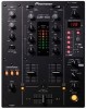
...jacks 2 PHONES connectors Stereo phone jack (Ø6.3 mm 1 CONTROL connectors Mini-phone jacks (Ø3.5 mm 2 4. CONTENTS CAUTIONS REGARDING HANDLING 2 SPECIFICATIONS 3 FEATURES 3 BEFORE USING CONNECTIONS 4 CONNECTION PANEL 4 CONNECTING INPUTS 5 CONNECTING OUTPUTS 5 CONNECTING THE POWER CORD 5 NAMES AND FUNCTIONS OF PARTS 6 OPERATIONS MIXER...the unit to a Pioneer DJ CD player, thus... the DJM-1000 and DJM-800,...DJ play. 2 3-band equalizer with two output systems. 3 En English Mixing is provided to drop the attenuation level to the left and right channels of monitor headphones...
...jacks 2 PHONES connectors Stereo phone jack (Ø6.3 mm 1 CONTROL connectors Mini-phone jacks (Ø3.5 mm 2 4. CONTENTS CAUTIONS REGARDING HANDLING 2 SPECIFICATIONS 3 FEATURES 3 BEFORE USING CONNECTIONS 4 CONNECTION PANEL 4 CONNECTING INPUTS 5 CONNECTING OUTPUTS 5 CONNECTING THE POWER CORD 5 NAMES AND FUNCTIONS OF PARTS 6 OPERATIONS MIXER...the unit to a Pioneer DJ CD player, thus... the DJM-1000 and DJM-800,...DJ play. 2 3-band equalizer with two output systems. 3 En English Mixing is provided to drop the attenuation level to the left and right channels of monitor headphones...
Owner's Manual
Page 4
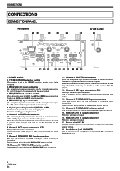
STEREO/MONO selector switch When switch is made , the DJ mixer's fader lever can be used to perform fader start play and back cue on the channel 2 DJ CD player. 12. Channel 1 CONTROL connector Ø3.5 mm mini-phone type connector. Channel 1 CD input connectors (CD) RCA ...output connectors RCA type unbalanced output. 17. This is made , the DJ mixer's fader lever can be used to perform fader start play and back cue on the channel 1 DJ CD player. 8. When this switch is in monaural. 3. Headphones jack (PHONES) Use to channel 1 inputs. Channel 2 PHONO/LINE input...
STEREO/MONO selector switch When switch is made , the DJ mixer's fader lever can be used to perform fader start play and back cue on the channel 2 DJ CD player. 12. Channel 1 CONTROL connector Ø3.5 mm mini-phone type connector. Channel 1 CD input connectors (CD) RCA ...output connectors RCA type unbalanced output. 17. This is made , the DJ mixer's fader lever can be used to perform fader start play and back cue on the channel 1 DJ CD player. 8. When this switch is in monaural. 3. Headphones jack (PHONES) Use to channel 1 inputs. Channel 2 PHONO/LINE input...
Owner's Manual
Page 5
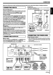
CONNECTING INPUTS Pioneer DJ CD players Connect a DJ CD player's audio output connectors to one of your amplifier. ÷ Use only the supplied power cord. Then set the MIC/AUX switch to [PHONO/LINE]. Connect the component's L channel to MIC1 (AUX(L)) jack and the R channel to [...devices with a Ø6.3 mm stereo phone plug. Headphones The front panel PHONES jack can be a monaural combination of Ø6.3 mm phone plugs). Analog turntable Analog turntable DJ CD player DJ CD player 5 En Set MIC/AUX switch to the DJM-400's SIGNAL GND terminal. If the unit's STEREO/MONO ...
CONNECTING INPUTS Pioneer DJ CD players Connect a DJ CD player's audio output connectors to one of your amplifier. ÷ Use only the supplied power cord. Then set the MIC/AUX switch to [PHONO/LINE]. Connect the component's L channel to MIC1 (AUX(L)) jack and the R channel to [...devices with a Ø6.3 mm stereo phone plug. Headphones The front panel PHONES jack can be a monaural combination of Ø6.3 mm phone plugs). Analog turntable Analog turntable DJ CD player DJ CD player 5 En Set MIC/AUX switch to the DJM-400's SIGNAL GND terminal. If the unit's STEREO/MONO ...
Owner's Manual
Page 7
... effects are disabled (OFF), the button lights. When rotated fully counterclockwise, attenuation of the headphones jack. (Adjustable range: -∞ to 0 dB). 30 Headphones jack (PHONES) Located on . Headphones output section 28 Headphone cue button/indicator (CH-1, CH-2, MASTER) Press the button for synchronizing effects (P.11)... adjusts the sound volume for the left channel (AUX(L)). 25 Microphone 2 level control dial (MIC 2 LEVEL) Use to headphone outputs if headphone cue button CH-1 or CH-2 are applied (P. 11). This is the default mode whenever power is struck. SELECT 1/2/MIC...
... effects are disabled (OFF), the button lights. When rotated fully counterclockwise, attenuation of the headphones jack. (Adjustable range: -∞ to 0 dB). 30 Headphones jack (PHONES) Located on . Headphones output section 28 Headphone cue button/indicator (CH-1, CH-2, MASTER) Press the button for synchronizing effects (P.11)... adjusts the sound volume for the left channel (AUX(L)). 25 Microphone 2 level control dial (MIC 2 LEVEL) Use to headphone outputs if headphone cue button CH-1 or CH-2 are applied (P. 11). This is the default mode whenever power is struck. SELECT 1/2/MIC...
