Leaflet
Page 1
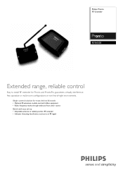
Single control solution for most devices & brands • Optional IR extension module controls hidden equipment • Radio frequency works through walls and from other rooms Quick and easy set-up • Adjustable antenna to reliably position RF extender • Indicator detecting interference sources to install RF extender for Pronto and ProntoPro guarantees virtually interferencefree operation in multi-room configurations or non-line-of-sight environments. Philips Pronto RF extender RFX6500 Extended range, reliable control Easy to an RF signal
Single control solution for most devices & brands • Optional IR extension module controls hidden equipment • Radio frequency works through walls and from other rooms Quick and easy set-up • Adjustable antenna to reliably position RF extender • Indicator detecting interference sources to install RF extender for Pronto and ProntoPro guarantees virtually interferencefree operation in multi-room configurations or non-line-of-sight environments. Philips Pronto RF extender RFX6500 Extended range, reliable control Easy to an RF signal
Leaflet
Page 2
... two types of RF used in direct line-of an RF extender. Radio frequency A radio technology that allows you to infrared. Specifications are subject to control components not in remote controls: RF to component, and RF to control traditional infrared equipment over a radio frequency network. RF interference indicator An interference indicator is a red blinking light that indicates the presence of Koninklijke Philips Electronics N.V. All Rights...
... two types of RF used in direct line-of an RF extender. Radio frequency A radio technology that allows you to infrared. Specifications are subject to control components not in remote controls: RF to component, and RF to control traditional infrared equipment over a radio frequency network. RF interference indicator An interference indicator is a red blinking light that indicates the presence of Koninklijke Philips Electronics N.V. All Rights...
User manual
Page 4
... in this user guide may be subject to change without prior consent of the copyright owner. All brand or product names are reserved. Royal Philips Electronics is not liable for omissions or for damages directly or indirectly resulting from the use of the RFX6500 / SBC LI910 RF Extender. The information in this manual or for technical or editorial errors in part is...
... in this user guide may be subject to change without prior consent of the copyright owner. All brand or product names are reserved. Royal Philips Electronics is not liable for omissions or for damages directly or indirectly resulting from the use of the RFX6500 / SBC LI910 RF Extender. The information in this manual or for technical or editorial errors in part is...
User manual
Page 5
... Receiver Unit 9 How to Do More 12 How to Set the Extender IDs 12 How to Avoid Interference from Other Prontos 13 How to Use a Longer Connection Cable 13 How to Fine-Tune the Installation Using the Dip Switches 14 How to Turn Off the IR Blaster 14 How to Set the Dual IR Emitter Power Levels 14 Troubleshooting 16 Specifications 17 User Guide...
... Receiver Unit 9 How to Do More 12 How to Set the Extender IDs 12 How to Avoid Interference from Other Prontos 13 How to Use a Longer Connection Cable 13 How to Fine-Tune the Installation Using the Dip Switches 14 How to Turn Off the IR Blaster 14 How to Set the Dual IR Emitter Power Levels 14 Troubleshooting 16 Specifications 17 User Guide...

User manual
Page 6
... Infrared (IR) remote controls do not work properly when obstacles between the remote control and the audio/video devices disturb the operating signal. This unit is limited space around the IR receivers of the devices, for IR commands. The Receiver unit receives RF signals sent out by using radio frequency (RF) as a carrier for instance in combination with the Blaster unit. When there is connected to transmit...
... Infrared (IR) remote controls do not work properly when obstacles between the remote control and the audio/video devices disturb the operating signal. This unit is limited space around the IR receivers of the devices, for IR commands. The Receiver unit receives RF signals sent out by using radio frequency (RF) as a carrier for instance in combination with the Blaster unit. When there is connected to transmit...

User manual
Page 7
Situation A: Your devices can be remotely controlled when they are not in the situation shown above can control all RF Extenders individually with your devices. The arrangements in the line of sight of furniture together with one or more Pronto Remote Controls. User Guide 4 How to Use the RF Extender Situation B: The RF Extender controls devices placed in an adjacent room. Situation C: The RF Extender is placed inside a closet, a rack or another piece of the remote control. You can also be combined.
Situation A: Your devices can be remotely controlled when they are not in the situation shown above can control all RF Extenders individually with your devices. The arrangements in the line of sight of furniture together with one or more Pronto Remote Controls. User Guide 4 How to Use the RF Extender Situation B: The RF Extender controls devices placed in an adjacent room. Situation C: The RF Extender is placed inside a closet, a rack or another piece of the remote control. You can also be combined.

User manual
Page 8
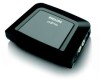
... following components: RF Extender Receiver unit, RF Extender Blaster unit, power adapter, connection cable, Dual IR emitters and screws. Remark The LED on . The installation of the RF Extender consists of 4 main steps: ■ Connecting the RF Extender; ■ Positioning the Blaster unit; ■ Installing the Dual IR emitters; ■ Positioning the Receiver unit. User Guide 5 EN How to the audio/video devices. 3 Plug the connection cable...
... following components: RF Extender Receiver unit, RF Extender Blaster unit, power adapter, connection cable, Dual IR emitters and screws. Remark The LED on . The installation of the RF Extender consists of 4 main steps: ■ Connecting the RF Extender; ■ Positioning the Blaster unit; ■ Installing the Dual IR emitters; ■ Positioning the Receiver unit. User Guide 5 EN How to the audio/video devices. 3 Plug the connection cable...

User manual
Page 9
For optimal IR reception, position the Blaster unit so the devices are located within the working range of the Blaster unit) in particular should be aimed at the audio/video devices. Make sure to Position the Blaster Unit For optimal results, the Blaster unit should be positioned horizontally, either facing... unit, as shown in a central position aimed directly at the devices, since the IR signals sent out by the IR blaster must reach the IR receivers of the devices. How to Install the RF Extender How to place the Blaster unit in the picture below. IR reflection area User Guide 6
For optimal IR reception, position the Blaster unit so the devices are located within the working range of the Blaster unit) in particular should be aimed at the audio/video devices. Make sure to Position the Blaster Unit For optimal results, the Blaster unit should be positioned horizontally, either facing... unit, as shown in a central position aimed directly at the devices, since the IR signals sent out by the IR blaster must reach the IR receivers of the devices. How to Install the RF Extender How to place the Blaster unit in the picture below. IR reflection area User Guide 6

User manual
Page 10
User Guide 7 Provide sufficient space to connect the power adapter and to the furniture using the mounting plate and screws, which are included. 1 Screw the mounting plate to Install the Dual IR Emitters The Dual IR emitters can be possible to attach the mounting plate to slide the Blaster unit back on the surface, ...
User Guide 7 Provide sufficient space to connect the power adapter and to the furniture using the mounting plate and screws, which are included. 1 Screw the mounting plate to Install the Dual IR Emitters The Dual IR emitters can be possible to attach the mounting plate to slide the Blaster unit back on the surface, ...

User manual
Page 11
How to Install the RF Extender 2 Attach the Dual IR emitters to a neighboring surface facing the IR receiver (for aesthetic purposes or when it is difficult to the IR receivers of the IR receivers. Make sure the Dual IR emitters are connected properly and that they are placed within range of the audio/video devices. User Guide 8 OR - Attach the Dual IR emitters directly to locate the IR receiver). -
How to Install the RF Extender 2 Attach the Dual IR emitters to a neighboring surface facing the IR receiver (for aesthetic purposes or when it is difficult to the IR receivers of the IR receivers. Make sure the Dual IR emitters are connected properly and that they are placed within range of the audio/video devices. User Guide 8 OR - Attach the Dual IR emitters directly to locate the IR receiver). -

User manual
Page 12
... direct it upwards. If the RF Extender and the Pronto Remote Control work properly in this scenario, they will cause the LED of the Receiver unit to create the worst-case scenario, by the rate at which the Receiver unit LED blinks and burns as little as WiFi base stations, audio/video devices, microwave ovens, or wireless telephones) are operated nearby...
... direct it upwards. If the RF Extender and the Pronto Remote Control work properly in this scenario, they will cause the LED of the Receiver unit to create the worst-case scenario, by the rate at which the Receiver unit LED blinks and burns as little as WiFi base stations, audio/video devices, microwave ovens, or wireless telephones) are operated nearby...

User manual
Page 13
... your Pronto Remote Control. Retracting in the antenna will also decrease the working range of both the Receiver unit and the Blaster unit should blink. User Guide 10 When sending commands with step 7. If the LED still blinks, continue with the next step. Note When the LED blinks only sporadically, with low light intensity, there are no problems with step 7. If the...
... your Pronto Remote Control. Retracting in the antenna will also decrease the working range of both the Receiver unit and the Blaster unit should blink. User Guide 10 When sending commands with step 7. If the LED still blinks, continue with the next step. Note When the LED blinks only sporadically, with low light intensity, there are no problems with step 7. If the...
User manual
Page 14
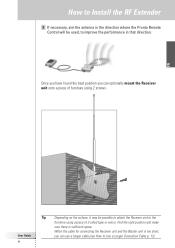
... cable for connecting the Receiver unit and the Blaster unit is sufficient space. EN User Guide 11 Tip Depending on the surface, it may be used, to improve the performance in that direction. How to Install the RF Extender 8 If necessary, aim the antenna in the direction where the Pronto Remote Control will be possible to attach the Receiver unit to Use a Longer Connection Cable...
... cable for connecting the Receiver unit and the Blaster unit is sufficient space. EN User Guide 11 Tip Depending on the surface, it may be used, to improve the performance in that direction. How to Install the RF Extender 8 If necessary, aim the antenna in the direction where the Pronto Remote Control will be possible to attach the Receiver unit to Use a Longer Connection Cable...
User manual
Page 15
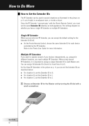
... Multiple RF Extenders If you can set the Extender IDs as illustrated in the picture on p. 4: out of your devices independently, e.g. grouped in different locations, you have a single RF Extender or multiple RF Extenders. The settings depend on whether you need multiple RF Extenders. How to Do ...Extender ID to each device controlled by turning the ID dial with the Pronto Remote Control, you can assign 16 Extender IDs (from 0 to 9 and from A to the Pronto User Guide for each Blaster unit. Single RF Extender When you use only one RF Extender, you must set the same Extender ...
... Multiple RF Extenders If you can set the Extender IDs as illustrated in the picture on p. 4: out of your devices independently, e.g. grouped in different locations, you have a single RF Extender or multiple RF Extenders. The settings depend on whether you need multiple RF Extenders. How to Do ...Extender ID to each device controlled by turning the ID dial with the Pronto Remote Control, you can assign 16 Extender IDs (from 0 to 9 and from A to the Pronto User Guide for each Blaster unit. Single RF Extender When you use only one RF Extender, you must set the same Extender ...
User manual
Page 16
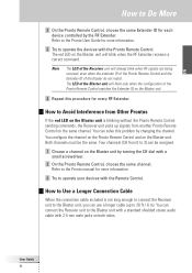
..., you can use a longer cable (up signals from 0 to 3) can connect the Receiver unit to the Blaster unit with a standard shielded stereo audio cable with the Remote Control. How to Avoid Interference from Other Prontos If the red LED on the Blaster unit. 4 Repeat this problem by changing the channel. Refer to the Pronto User Guide for more information. 3 Try to operate your devices with 2.5 mm...
..., you can use a longer cable (up signals from 0 to 3) can connect the Receiver unit to the Blaster unit with a standard shielded stereo audio cable with the Remote Control. How to Avoid Interference from Other Prontos If the red LED on the Blaster unit. 4 Repeat this problem by changing the channel. Refer to the Pronto User Guide for more information. 3 Try to operate your devices with 2.5 mm...

User manual
Page 17
... operate 2 identical devices that interferes with Dual IR emitters only, you decide to control the audio/video devices with IR signals, such as a plasma TV set. How to Turn Off the IR Blaster When you can lower the power levels of the Dual IR emitters, in wired IR solutions using 2 RF Extenders. When you use dip switches 1 to 4 to Fine-Tune the Installation Using...
... operate 2 identical devices that interferes with Dual IR emitters only, you decide to control the audio/video devices with IR signals, such as a plasma TV set. How to Turn Off the IR Blaster When you can lower the power levels of the Dual IR emitters, in wired IR solutions using 2 RF Extenders. When you use dip switches 1 to 4 to Fine-Tune the Installation Using...

User manual
Page 18
EN User Guide 15 default setting) Switch 1 Switch 2 Switch 3 Switch 4 0 (Off) 0 (Off) 1 (On) 1 (On) 0 (Off) 1 (On) 0 (Off) 1 (On) 0 (Off) 0 (Off) 1 (On) 1 (On) 0 (Off) 1 (On) 0 (Off) 1 (On) Remark The Dual IR emitters still send out IR signals when the power level is never completely turned off. The emission is set to Do More You can set the power level as indicated below: Power level (Operating distance) 0 (0.7 m) 1 (1.5 m) 2 (2.0 m) 3 (2.5 m - How to zero.
EN User Guide 15 default setting) Switch 1 Switch 2 Switch 3 Switch 4 0 (Off) 0 (Off) 1 (On) 1 (On) 0 (Off) 1 (On) 0 (Off) 1 (On) 0 (Off) 0 (Off) 1 (On) 1 (On) 0 (Off) 1 (On) 0 (Off) 1 (On) Remark The Dual IR emitters still send out IR signals when the power level is never completely turned off. The emission is set to Do More You can set the power level as indicated below: Power level (Operating distance) 0 (0.7 m) 1 (1.5 m) 2 (2.0 m) 3 (2.5 m - How to zero.
User manual
Page 19
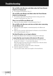
... front of the emitter. User Guide 16 Troubleshooting The red LED on the Receiver unit blinks when the Pronto Remote Control is not being used in the proximity of the Receiver unit. See p. 5. ■ Make sure the connection cable between the Receiver unit and the Blaster unit is connected properly. I cannot find the exact location of the device's IR receiver ■ Set the Dual IR emitters...
... front of the emitter. User Guide 16 Troubleshooting The red LED on the Receiver unit blinks when the Pronto Remote Control is not being used in the proximity of the Receiver unit. See p. 5. ■ Make sure the connection cable between the Receiver unit and the Blaster unit is connected properly. I cannot find the exact location of the device's IR receiver ■ Set the Dual IR emitters...
User manual
Page 20
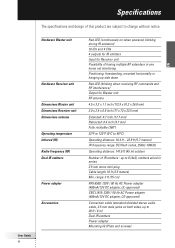
..., CE-approved) Connection cable (standard shielded stereo audio cable, 2.5 mm male jacks on when powered, blinking during IR emission) 16 IDs and 4 CHs 4 outputs for IR emitters Input for Receiver unit Possibility of having multiple RF extenders in one home not interfering Positioning: freestanding, mounted horizontally or hanging up side down Red LED (blinking when receiving RF commands and RF interference...
..., CE-approved) Connection cable (standard shielded stereo audio cable, 2.5 mm male jacks on when powered, blinking during IR emission) 16 IDs and 4 CHs 4 outputs for IR emitters Input for Receiver unit Possibility of having multiple RF extenders in one home not interfering Positioning: freestanding, mounted horizontally or hanging up side down Red LED (blinking when receiving RF commands and RF interference...
User manual
Page 57
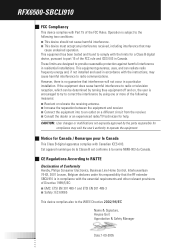
...: User changes or modifications not expressly approved by turning thee equipment off and on a different circuit from the receiver. ■ Consult the dealer or an experienced radio/TV technician for a Class B digital device, pursuant to an outlet on , the user is encouraged to try to correct the interference by using one or more of Conformity Hereby, Philips Consumer Electronics, Business Line Home Control...
...: User changes or modifications not expressly approved by turning thee equipment off and on a different circuit from the receiver. ■ Consult the dealer or an experienced radio/TV technician for a Class B digital device, pursuant to an outlet on , the user is encouraged to try to correct the interference by using one or more of Conformity Hereby, Philips Consumer Electronics, Business Line Home Control...


