Assembly Instructions
Page 2
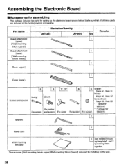
... cord Wall-mounting template 1 Ujnsgetethmepraatell-Taonudnt2- Make sure that all of these parts are used for installing on the wall. 38 Part Name Illustration/Quantity .- UB-5315 UB-5815 ) CIty Remarks Board attachment 1 (upper) ['Wall-mounting fixture (upper)] Board attachment 1 (lower) ['Wall-mounting fixture (lower)] 1 Cover (upper) 1 Cover (lower) Screws ... 6 f: :: :) For screen 6 O For screen Screen Page 41, Step 11 Printer Page 43, Step 17 Cover (lower) Page 45, Step 22 * 1 screw for UB-5315 ** 2 screws for setting up the electronic board shown below.
... cord Wall-mounting template 1 Ujnsgetethmepraatell-Taonudnt2- Make sure that all of these parts are used for installing on the wall. 38 Part Name Illustration/Quantity .- UB-5315 UB-5815 ) CIty Remarks Board attachment 1 (upper) ['Wall-mounting fixture (upper)] Board attachment 1 (lower) ['Wall-mounting fixture (lower)] 1 Cover (upper) 1 Cover (lower) Screws ... 6 f: :: :) For screen 6 O For screen Screen Page 41, Step 11 Printer Page 43, Step 17 Cover (lower) Page 45, Step 22 * 1 screw for UB-5315 ** 2 screws for setting up the electronic board shown below.

Assembly Instructions
Page 12
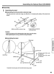
...) O 48 Releasing the lock Part name Q'ty 0 Base pipe 2 a) Screw 9,Iiiiiii::::: Height i t © Reinforce pipe I ttb 1© adjustment handle 1 4 Extension pipe © S (For UB-5315) Extension pipe CD L (For UB-5815) eff:fi I j 1 0 Nut 1® Cap 0 4 2 © Side pipe l Slide plate O (Left) 4( Slide plate 0 (Right) © Fixing plate l, 2 © Step frame 1 \- 5 Fall-preven...
...) O 48 Releasing the lock Part name Q'ty 0 Base pipe 2 a) Screw 9,Iiiiiii::::: Height i t © Reinforce pipe I ttb 1© adjustment handle 1 4 Extension pipe © S (For UB-5315) Extension pipe CD L (For UB-5815) eff:fi I j 1 0 Nut 1® Cap 0 4 2 © Side pipe l Slide plate O (Left) 4( Slide plate 0 (Right) © Fixing plate l, 2 © Step frame 1 \- 5 Fall-preven...
Assembly Instructions
Page 13
... the stand 0 Slide sheet 9 °Base pipe Slide sheet 0 CD at 0 sn E © Side pipe 0 Reinforce pipe Extension pipe S C) is used for UB-5315. 7 Extension pipe L ® is used for UB-5815. Caution • Install and always set the fall -prevention extension legs are effective in increasing the safety of the electronic board...
... the stand 0 Slide sheet 9 °Base pipe Slide sheet 0 CD at 0 sn E © Side pipe 0 Reinforce pipe Extension pipe S C) is used for UB-5315. 7 Extension pipe L ® is used for UB-5815. Caution • Install and always set the fall -prevention extension legs are effective in increasing the safety of the electronic board...
Assembly Instructions
Page 16
... occur until this wall-mounting fixture, we strongly recommend consulting with the unit. Accidental electric leakage from the wall-mounting fixture bolts to mortared walls. I. UB-5315 is within 3 m (9'101/8 "), and not located behind the Panaboard. 52 Before attempting installation of adequate size for hardware installation Screw driver (Both phillips (+) and slotted... (176 lbs.). The installer needs to know the type of construction used for the wall intended for this installation and the location of supporting flush- UB-5315 is capable of wall studs.
... occur until this wall-mounting fixture, we strongly recommend consulting with the unit. Accidental electric leakage from the wall-mounting fixture bolts to mortared walls. I. UB-5315 is within 3 m (9'101/8 "), and not located behind the Panaboard. 52 Before attempting installation of adequate size for hardware installation Screw driver (Both phillips (+) and slotted... (176 lbs.). The installer needs to know the type of construction used for the wall intended for this installation and the location of supporting flush- UB-5315 is capable of wall studs.
Assembly Instructions
Page 17
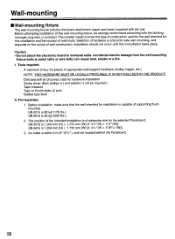
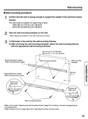
Caution The wall must be capable of supporting at least 784N [80 kgf (176 lbs.)] for UB-5315 931N [95 kgf (209 lbs.)] for UB-5815. 2 Tape the wall-mounting template on the wall. • When taping the template on pages 39 to 45 for attaching the ... fixtures. 2) After removing the wall-mounting template, attach the wall-mounting fixtures with the appropriate wall-mounting hardware. 812 mm (2'8") for UB-5315 900 mm (2'117/16") for UB-5815 Board attachment (upper) (Wall-mounting fixture upper) Wall-mounting hardware up Wall-mounting template Board attachment (lower) (Wall-mounting fixture ...
Caution The wall must be capable of supporting at least 784N [80 kgf (176 lbs.)] for UB-5315 931N [95 kgf (209 lbs.)] for UB-5815. 2 Tape the wall-mounting template on the wall. • When taping the template on pages 39 to 45 for attaching the ... fixtures. 2) After removing the wall-mounting template, attach the wall-mounting fixtures with the appropriate wall-mounting hardware. 812 mm (2'8") for UB-5315 900 mm (2'117/16") for UB-5815 Board attachment (upper) (Wall-mounting fixture upper) Wall-mounting hardware up Wall-mounting template Board attachment (lower) (Wall-mounting fixture ...


