
WVBP330 User Guide
Page 1
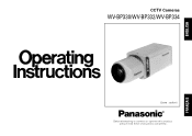
FRANÇAIS ENGLISH CCTV Cameras WV-BP330/WV-BP332/WV-BP334 (Lens : option) Before attempting to connect or operate this product, please read these instructions completely.
FRANÇAIS ENGLISH CCTV Cameras WV-BP330/WV-BP332/WV-BP334 (Lens : option) Before attempting to connect or operate this product, please read these instructions completely.

WVBP330 User Guide
Page 2
.... Model No. REFER SERVICING TO QUALIFIED SERVICE PERSONNEL. For U.S.A Warning: This equipment generates and uses radio frequency energy and if not installed and used properly, i.e., in the literature accompa-nying the appliance. NO USER SERVICEABLE PARTS INSIDE. You should note the serial number of this unit in the space provided and retain this product may be found to comply with the instruction manual...
.... Model No. REFER SERVICING TO QUALIFIED SERVICE PERSONNEL. For U.S.A Warning: This equipment generates and uses radio frequency energy and if not installed and used properly, i.e., in the literature accompa-nying the appliance. NO USER SERVICEABLE PARTS INSIDE. You should note the serial number of this unit in the space provided and retain this product may be found to comply with the instruction manual...
WVBP330 User Guide
Page 3
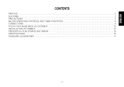
ENGLISH CONTENTS PREFACE ...2 FEATURES ...2 PRECAUTIONS ...3 MAJOR OPERATING CONTROLS AND THEIR FUNCTIONS 4 CONNECTIONS ...8 FOCUS OR FLANGE-BACK ADJUSTMENT ...13 INSTALLATION OF CAMERA ...14 PREVENTION OF BLOOMING AND SMEAR ...15 SPECIFICATIONS ...16 STANDARD ACCESSORIES ...17 -1-
ENGLISH CONTENTS PREFACE ...2 FEATURES ...2 PRECAUTIONS ...3 MAJOR OPERATING CONTROLS AND THEIR FUNCTIONS 4 CONNECTIONS ...8 FOCUS OR FLANGE-BACK ADJUSTMENT ...13 INSTALLATION OF CAMERA ...14 PREVENTION OF BLOOMING AND SMEAR ...15 SPECIFICATIONS ...16 STANDARD ACCESSORIES ...17 -1-
WVBP330 User Guide
Page 4
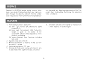
... fixed iris lens by use of a 1/3-inch interline transfer CCD image sensor having 768 horizontal pixels (pic- Selectable auto iris control signal for advanced video surveillance. 6. Shooting of shoot indoor scenes with F1.4 lenses 4. Signal-to the center of the screen/OFF: Effective if the object is given to -noise ratio of 50 dB 3. FEATURES 1. PREFACE Panasonic's WV-BP330 series digital cameras introduce...
... fixed iris lens by use of a 1/3-inch interline transfer CCD image sensor having 768 horizontal pixels (pic- Selectable auto iris control signal for advanced video surveillance. 6. Shooting of shoot indoor scenes with F1.4 lenses 4. Signal-to the center of the screen/OFF: Effective if the object is given to -noise ratio of 50 dB 3. FEATURES 1. PREFACE Panasonic's WV-BP330 series digital cameras introduce...
WVBP330 User Guide
Page 5
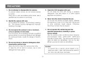
...user serviceable parts inside. Do not abuse the camera. Do not use or not, never aim it at bright objects. Caution: To prevent fire or electric shock hazard, a UL listed wire (VW-1, style 1007) should be damaged by improper handling or storage. 3. The camera could be used... Avoid striking, shaking, etc. Turn the power off immediately and ask a qualified service person for servicing. 2. Use a dry cloth to operate it in use strong or abrasive detergents when cleaning the camera body. Clean the CCD faceplate with care. Use lens tissue or a cotton tipped applicator ...
...user serviceable parts inside. Do not abuse the camera. Do not use or not, never aim it at bright objects. Caution: To prevent fire or electric shock hazard, a UL listed wire (VW-1, style 1007) should be damaged by improper handling or storage. 3. The camera could be used... Avoid striking, shaking, etc. Turn the power off immediately and ask a qualified service person for servicing. 2. Use a dry cloth to operate it in use strong or abrasive detergents when cleaning the camera body. Clean the CCD faceplate with care. Use lens tissue or a cotton tipped applicator ...

WVBP330 User Guide
Page 6
PHASE VIDEO LEVEL L H WV-BP330 -4- PHASE VIDEO LEVEL L H DC 12V IN GEN-LOCK OFF ELC OFF DC Hi-Z VIDEO OUT AGC ON ALC BLC ON VIDEO G/L 75 Ω VIDEO LEVEL L H AC 24V IN 12 GEN-LOCK GND LL INT OFF AGC ON ELC ALC OFF BLC ON DC VIDEO Hi-Z G/L 75 Ω VIDEO OUT V. MAJOR OPERATING CONTROLS AND THEIR FUNCTIONS GEN-LOCK LL INT OFF AGC ON ELC ALC OFF BLC ON DC VIDEO Hi-Z G/L 75 Ω VIDEO OUT V.
PHASE VIDEO LEVEL L H WV-BP330 -4- PHASE VIDEO LEVEL L H DC 12V IN GEN-LOCK OFF ELC OFF DC Hi-Z VIDEO OUT AGC ON ALC BLC ON VIDEO G/L 75 Ω VIDEO LEVEL L H AC 24V IN 12 GEN-LOCK GND LL INT OFF AGC ON ELC ALC OFF BLC ON DC VIDEO Hi-Z G/L 75 Ω VIDEO OUT V. MAJOR OPERATING CONTROLS AND THEIR FUNCTIONS GEN-LOCK LL INT OFF AGC ON ELC ALC OFF BLC ON DC VIDEO Hi-Z G/L 75 Ω VIDEO OUT V.
WVBP330 User Guide
Page 7
... operation. INT: When no signal is supplied to the GEN-LOCK connector, the camera synchronization mode is automatically set to external synchronization. Whenever the gen-lock video signal is supplied to the GENLOCK connector, the camera synchronization mode is set to internal 2:1 interlace. Note: Set this ring clockwise for a C-mount lens or counterclockwise for connecting the auto iris lens by automatic increase of the video amplifier as a standard accessory (Part...
... operation. INT: When no signal is supplied to the GEN-LOCK connector, the camera synchronization mode is automatically set to external synchronization. Whenever the gen-lock video signal is supplied to the GENLOCK connector, the camera synchronization mode is set to internal 2:1 interlace. Note: Set this ring clockwise for a C-mount lens or counterclockwise for connecting the auto iris lens by automatic increase of the video amplifier as a standard accessory (Part...
WVBP330 User Guide
Page 8
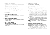
... be adjusted by the lens when the auto iris lens requiring the video drive signal is mounted on the camera. !6 Video Output Connector (VIDEO OUT) This connector is for connecting with this camera. !0 Automatic Light Control / Electronic Light Control Selector (ALC , ELC) Lets you select the mode according to the lens type that is used with this camera. !1 Back Light Compensation Mode Selector (BLC ON, OFF) Lets you select the mode according to the position of...
... be adjusted by the lens when the auto iris lens requiring the video drive signal is mounted on the camera. !6 Video Output Connector (VIDEO OUT) This connector is for connecting with this camera. !0 Automatic Light Control / Electronic Light Control Selector (ALC , ELC) Lets you select the mode according to the lens type that is used with this camera. !1 Back Light Compensation Mode Selector (BLC ON, OFF) Lets you select the mode according to the position of...

WVBP330 User Guide
Page 9
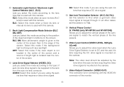
To prevent fire or electric shock hazard, use a UL listed wire VW-1, style 1007 cable for synchronization. Connect to the GND terminal when the power is for connecting an external system for the Input Terminal. -7- !7 Gen-lock Input Connector (GEN-LOCK) This connector is supplied from a 24V AC power source. 2. Make sure to connect the grounding lead to 12V DC (10.5V-16V) or 24V AC (19.5V-28V) class 2 power supply only. Cautions: 1.
To prevent fire or electric shock hazard, use a UL listed wire VW-1, style 1007 cable for synchronization. Connect to the GND terminal when the power is for connecting an external system for the Input Terminal. -7- !7 Gen-lock Input Connector (GEN-LOCK) This connector is supplied from a 24V AC power source. 2. Make sure to connect the grounding lead to 12V DC (10.5V-16V) or 24V AC (19.5V-28V) class 2 power supply only. Cautions: 1.
WVBP330 User Guide
Page 10
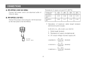
... (12V DC) Connect the power cord to an electrical outlet of power supply unit VA − 12 L standard = (meters) 0.42 x R VA − 16 L minimum = (meters) 0.42 x R VA − 10.5 L maximum = (meters) 0.42 x R -8- WV-BP330 (120V AC 60Hz) Connect the power cord to the...83mm2) 0.078 0.050 0.030 0.018 0.026 0.017 0.010 0.006 • Calculation of maximum cable length between camera and power supply : 10.5V DC ≤ VA − (R x 0.42 x L) ≤ 16V DC L : Cable length (meters) R : Resistance of copper wire (Ω/meters) VA : DC output voltage of 120V AC 60Hz...
... (12V DC) Connect the power cord to an electrical outlet of power supply unit VA − 12 L standard = (meters) 0.42 x R VA − 16 L minimum = (meters) 0.42 x R VA − 10.5 L maximum = (meters) 0.42 x R -8- WV-BP330 (120V AC 60Hz) Connect the power cord to the...83mm2) 0.078 0.050 0.030 0.018 0.026 0.017 0.010 0.006 • Calculation of maximum cable length between camera and power supply : 10.5V DC ≤ VA − (R x 0.42 x L) ≤ 16V DC L : Cable length (meters) R : Resistance of copper wire (Ω/meters) VA : DC output voltage of 120V AC 60Hz...
WVBP330 User Guide
Page 11
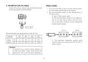
..., a UL listed wire (VW-1, style 1007) should be used for DC 12V or AC 24V Input Terminals. Video Cable 1. A. Use a 75Ω coaxial cable. Do not change the positions after setting. C. It is recommended to the 75Ω position on the other monitors. B. Set the termination switch to use a monitor whose resolution is shown below. -9- Set the termination switch to the 75Ω position on the last monitor and to...
..., a UL listed wire (VW-1, style 1007) should be used for DC 12V or AC 24V Input Terminals. Video Cable 1. A. Use a 75Ω coaxial cable. Do not change the positions after setting. C. It is recommended to the 75Ω position on the other monitors. B. Set the termination switch to use a monitor whose resolution is shown below. -9- Set the termination switch to the 75Ω position on the last monitor and to...

WVBP330 User Guide
Page 12
Wiring precautions: • Do not bend the coaxial cable into a curve whose radius is smaller than 10 times the cable's diameter. • Never staple the cable, not even with circular staples. All of the above will occur. • Never crush or pinch the cable. Type of the cable and cause poor picture quality. -10- Impedance mismatching will change the impedance of coaxial cable Recommended maximum cable length RG-59/U RG-6/U RG-11/U RG-15/U (3C-2V) (5C-2V) (7C-2V) (10C-2V) (m) 250 500 600 800 (ft) 825 1 650 1 980 2 640 3.
Wiring precautions: • Do not bend the coaxial cable into a curve whose radius is smaller than 10 times the cable's diameter. • Never staple the cable, not even with circular staples. All of the above will occur. • Never crush or pinch the cable. Type of the cable and cause poor picture quality. -10- Impedance mismatching will change the impedance of coaxial cable Recommended maximum cable length RG-59/U RG-6/U RG-11/U RG-15/U (3C-2V) (5C-2V) (7C-2V) (10C-2V) (m) 250 500 600 800 (ft) 825 1 650 1 980 2 640 3.

WVBP330 User Guide
Page 13
... diagram below. The pin assignment of Auto Iris Lens Connector Install the lens connector (YFE4191J100) when using a video drive ALC lens. Connector Cover Heat Shrinkable Tubes Automatic Iris Lens Iris Control Cable Connector Note: When the iris control cable is as follows: Pin 1: Power source; +9V DC, 50mA max. The installation should be made by qualified service personnel or system installers. (1) Cut the iris control cable at the edge of the lens connector to the VIDEO position...
... diagram below. The pin assignment of Auto Iris Lens Connector Install the lens connector (YFE4191J100) when using a video drive ALC lens. Connector Cover Heat Shrinkable Tubes Automatic Iris Lens Iris Control Cable Connector Note: When the iris control cable is as follows: Pin 1: Power source; +9V DC, 50mA max. The installation should be made by qualified service personnel or system installers. (1) Cut the iris control cable at the edge of the lens connector to the VIDEO position...
WVBP330 User Guide
Page 14
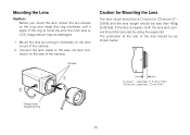
... the lens and camera should be secured by turning it stops. Connect the lens cable to the auto iris lens connector on the lens mount of the camera. 2. The protrusion at the end, the inner lens or CCD image sensor may be as shown below: 1 2 C-mount: Less than 11.5 mm (7/16") CS-mount: Less than 450g (0.99 lbs). Mount the lens by using the supporter. Screws Caution for Mounting the Lens The lens mount should be a C-mount...
... the lens and camera should be secured by turning it stops. Connect the lens cable to the auto iris lens connector on the lens mount of the camera. 2. The protrusion at the end, the inner lens or CCD image sensor may be as shown below: 1 2 C-mount: Less than 11.5 mm (7/16") CS-mount: Less than 450g (0.99 lbs). Mount the lens by using the supporter. Screws Caution for Mounting the Lens The lens mount should be a C-mount...
WVBP330 User Guide
Page 15
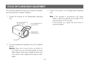
... the monitor. Turn the flange-back adjusting ring to reduce the glare. FOCUS OR FLANGE-BACK ADJUSTMENT The following adjustment should be made by force, the inner lens or CCD image sensor may appear at the edge of the camera picture on the flange-back adjusting ring. If the ring is rotated by qualified service personnel or system installers. 3. Focus adjustment for CS-mount lens Focus adjustment for C-mount lens Note...
... the monitor. Turn the flange-back adjusting ring to reduce the glare. FOCUS OR FLANGE-BACK ADJUSTMENT The following adjustment should be made by force, the inner lens or CCD image sensor may appear at the edge of the camera picture on the flange-back adjusting ring. If the ring is rotated by qualified service personnel or system installers. 3. Focus adjustment for CS-mount lens Focus adjustment for C-mount lens Note...
WVBP330 User Guide
Page 16
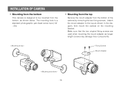
... mount adapter to be mounted from the bottom of the camera by removing the two fixing screws. The mounting hole is designed to the top as longer length screws may damage inner components. Fixing Screws Mount Adapter -14- Make sure that the two original fixing screws are used when mounting the mount adapter as shown in the diagram, then mount the camera on the mounting bracket...
... mount adapter to be mounted from the bottom of the camera by removing the two fixing screws. The mounting hole is designed to the top as longer length screws may damage inner components. Fixing Screws Mount Adapter -14- Make sure that the two original fixing screws are used when mounting the mount adapter as shown in the diagram, then mount the camera on the mounting bracket...
WVBP330 User Guide
Page 17
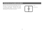
Smear Bright object -15- PREVENTION OF BLOOMING AND SMEAR When the camera is aimed at a bright light, such as a spot light, or a surface that reflects bright light, smear or blooming may appear. Therefore, the camera should be operated carefully in the vicinity of extremely bright objects to avoid smear or blooming. ;;;;;;
Smear Bright object -15- PREVENTION OF BLOOMING AND SMEAR When the camera is aimed at a bright light, such as a spot light, or a surface that reflects bright light, smear or blooming may appear. Therefore, the camera should be operated carefully in the vicinity of extremely bright objects to avoid smear or blooming. ;;;;;;
WVBP330 User Guide
Page 18
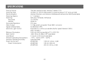
SPECIFICATIONS Pick-up Device: Scanning Area: Synchronization: Scanning System: Scanning: Horizontal: Vertical: Horizontal Resolution: Video Output: Signal-to-Noise Ratio: Electronic Light Control: Minimum Illumination: Gain Control: Lens Mount: Ambient Operating Temperature: Ambient Operating Humidity: Power Source and Power Consumption: 768 (H) x 494 (V) pixels, Interline Transfer CCD ... connector 50 dB (AGC OFF) Equivalent to continuous variable shutter speed between 1/60 s and 1/10 000 s 0.08 lx (0.008 footcandle) at F1.4, AGC ON AGC ON (+18 dB) or OFF selectable C-mount or CS-mount...
SPECIFICATIONS Pick-up Device: Scanning Area: Synchronization: Scanning System: Scanning: Horizontal: Vertical: Horizontal Resolution: Video Output: Signal-to-Noise Ratio: Electronic Light Control: Minimum Illumination: Gain Control: Lens Mount: Ambient Operating Temperature: Ambient Operating Humidity: Power Source and Power Consumption: 768 (H) x 494 (V) pixels, Interline Transfer CCD ... connector 50 dB (AGC OFF) Equivalent to continuous variable shutter speed between 1/60 s and 1/10 000 s 0.08 lx (0.008 footcandle) at F1.4, AGC ON AGC ON (+18 dB) or OFF selectable C-mount or CS-mount...

WVBP330 User Guide
Page 19
STANDARD ACCESSORIES Body Cap 1 pc. ALC Lens Connector (YFE4191J100 1 pc. -17- Specifications are approximate. Dimensions (without lens): Weights (without lens): 67 (W) x 55 (H) x 123 (D) mm [2-5/8" (W) x 2-3/16" (H) x 4-13/16" (D)] WV-BP330: 0.62kg (1.40lbs) WV-BP332: 0.445kg (0.98lbs) WV-BP334: 0.470kg (1.04lbs) Weights and dimensions indicated are subject to change without notice.
STANDARD ACCESSORIES Body Cap 1 pc. ALC Lens Connector (YFE4191J100 1 pc. -17- Specifications are approximate. Dimensions (without lens): Weights (without lens): 67 (W) x 55 (H) x 123 (D) mm [2-5/8" (W) x 2-3/16" (H) x 4-13/16" (D)] WV-BP330: 0.62kg (1.40lbs) WV-BP332: 0.445kg (0.98lbs) WV-BP334: 0.470kg (1.04lbs) Weights and dimensions indicated are subject to change without notice.
WVBP330 User Guide
Page 40
... MATSUSHITA ELECTRIC OF PUERTO RICO INC. San Gabriel Industrial Park 65th Infantry Ave. Panasonic Digital Communications & Security Company Unit of Matsushita Electric Corporation of America Security Systems Group www.panasonic.com/cctv Executive Office: One Panasonic Way 3E-7, Secaucus, New Jersey 07094 Zone Office Eastern: One Panasonic Way, Secaucus, NJ 07094 (201) 348-7303 Central: 1707 N.Randal Road, Elgin...
... MATSUSHITA ELECTRIC OF PUERTO RICO INC. San Gabriel Industrial Park 65th Infantry Ave. Panasonic Digital Communications & Security Company Unit of Matsushita Electric Corporation of America Security Systems Group www.panasonic.com/cctv Executive Office: One Panasonic Way 3E-7, Secaucus, New Jersey 07094 Zone Office Eastern: One Panasonic Way, Secaucus, NJ 07094 (201) 348-7303 Central: 1707 N.Randal Road, Elgin...


