Installation Instructions
Page 1
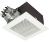
... Header Installation) 6 InstallationIII (In Existing Construction) 7 Maintenance 7-8 Practical guide to comply with instructions could result in personal injury and/or property damage. INSTALLATION INSTRUCTIONS Ventilating Fan FV-20VQ3 FV-30VQ3 FV-40VQ3 Panasonid READ AND SAVE THESE INSTRUCTIONS. Failure to installation 8 Product Service 8 Please read these instructions carefully before attempting to...
... Header Installation) 6 InstallationIII (In Existing Construction) 7 Maintenance 7-8 Practical guide to comply with instructions could result in personal injury and/or property damage. INSTALLATION INSTRUCTIONS Ventilating Fan FV-20VQ3 FV-30VQ3 FV-40VQ3 Panasonid READ AND SAVE THESE INSTRUCTIONS. Failure to installation 8 Product Service 8 Please read these instructions carefully before attempting to...
Installation Instructions
Page 2
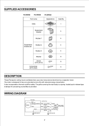
... with reduced energy consumption. Earth ground Earth ground 2 The motor is a spring- loaded,quick-release type. WIRING DIAGRAM Motor Fan body Red White Black Junction box Capacitor White White Black Black Green Green Green Neutral Switch Power supply Live AC120V 60Hz (not included... Rubber 1 4 103: Suspension Rubber 2 4 bracket set Rubber 3 0 4 Washer CD 8 Screw (ST4.2X12) 8 1) Long screw (ST4.2X20) El l' 6 DESCRIPTION These Panasonic ceiling mount ventilation fans use a low noise sirocco fan driven by a capacitor motor. A damper for safety.
... with reduced energy consumption. Earth ground Earth ground 2 The motor is a spring- loaded,quick-release type. WIRING DIAGRAM Motor Fan body Red White Black Junction box Capacitor White White Black Black Green Green Green Neutral Switch Power supply Live AC120V 60Hz (not included... Rubber 1 4 103: Suspension Rubber 2 4 bracket set Rubber 3 0 4 Washer CD 8 Screw (ST4.2X12) 8 1) Long screw (ST4.2X20) El l' 6 DESCRIPTION These Panasonic ceiling mount ventilation fans use a low noise sirocco fan driven by a capacitor motor. A damper for safety.
Installation Instructions
Page 3
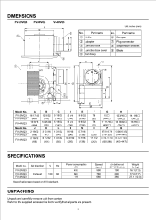
...-447) I 14 1/16O (357O) 16 5/8O (422O) SPECIFICATIONS Model no. F L M Model No. Part name 0 Grille © Adapter ® Junction box © Junction box cover © Fan body No.
...-447) I 14 1/16O (357O) 16 5/8O (422O) SPECIFICATIONS Model no. F L M Model No. Part name 0 Grille © Adapter ® Junction box © Junction box cover © Fan body No.
Installation Instructions
Page 4
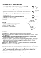
...hot surfaces, chemicals or other hidden utilities. A. 8. Fig. A (Cooking area) Do not install above or CAUTION: inside this ventilating fan where air temperature may cause harmonic distortion which can be properly grounded. For general ventilating use this unit with any questions, contact to ... Cooking equipment Floor Fig. Installation work and electrical wiring must be reached from being switched on or near the fan, motor or junction box. 5. Ducted fans must be done by qualified person(s) in the manner intended by the National Fire Protection Association (NFPA), and the...
...hot surfaces, chemicals or other hidden utilities. A. 8. Fig. A (Cooking area) Do not install above or CAUTION: inside this ventilating fan where air temperature may cause harmonic distortion which can be properly grounded. For general ventilating use this unit with any questions, contact to ... Cooking equipment Floor Fig. Installation work and electrical wiring must be reached from being switched on or near the fan, motor or junction box. 5. Ducted fans must be done by qualified person(s) in the manner intended by the National Fire Protection Association (NFPA), and the...
Installation Instructions
Page 5
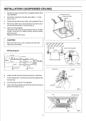
... box cover carefully so that lead wires are not pinched. Refer to wiring diagram Using wire nuts, connect house power wires to ventilating fan wires (Fig. 3): black to junction box knockout hole. (7/8 inch) (Fig. 3) 5. Connect plug connector to white; Disconnect plug... connector from receptacle before starting installation. 2. Wiring Diagram Motor Fan body Red White Black Junction box Capacitor White White Black Black Neutral Switch Power supply Live AC120V 60Hz Green Green (not included) Green Earth...
... box cover carefully so that lead wires are not pinched. Refer to wiring diagram Using wire nuts, connect house power wires to ventilating fan wires (Fig. 3): black to junction box knockout hole. (7/8 inch) (Fig. 3) 5. Connect plug connector to white; Disconnect plug... connector from receptacle before starting installation. 2. Wiring Diagram Motor Fan body Red White Black Junction box Capacitor White White Black Black Neutral Switch Power supply Live AC120V 60Hz Green Green (not included) Green Earth...
Installation Instructions
Page 6
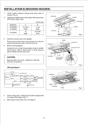
....2X20). (Figs. 5 & 6) inches (mm) Model No. Install the ventilating fan to junction box knockout hole. (7/8 inch) (Fig. 6) 4. Ceiling joist 6 Long screws (ST4.2X20) Wiring Diagram Motor Fan body Red White Black Junction box Capacitor White White Black Black Neutral SwitchPower supply Live ... duct Junction box cover Fig. 6 Fig. 7 5. Insert the circular duct to black; Using wire nuts, connect house power wires to ventilating fan wires: black to the adapter. Finish ceiling work. Mount grille to white; Install header between ceiling joists using nails or screws. (Fig. 5)...
....2X20). (Figs. 5 & 6) inches (mm) Model No. Install the ventilating fan to junction box knockout hole. (7/8 inch) (Fig. 6) 4. Ceiling joist 6 Long screws (ST4.2X20) Wiring Diagram Motor Fan body Red White Black Junction box Capacitor White White Black Black Neutral SwitchPower supply Live ... duct Junction box cover Fig. 6 Fig. 7 5. Insert the circular duct to black; Using wire nuts, connect house power wires to ventilating fan wires: black to the adapter. Finish ceiling work. Mount grille to white; Install header between ceiling joists using nails or screws. (Fig. 5)...
Installation Instructions
Page 7
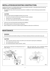
...down.) (Fig. 8) detergent.) Wipe dry with installation. 2. Inspect duct work can be run to planning location. 3. Plan suitable location for fan body (next to enter motor. 3. Take the following precautions before working on unit. MAINTENANCE WARNING Disconnect power source before installation. Do not soak.... 1. Wiring can be done and that : 1. CAUTION 1. Remove grille. (Squeeze mounting spring and pull 2. Routine maintenace of the fan must be done every year. No wiring or other such chemicals for proper ventilation. 2. Do not damp water to ceiling joist). 4. To ...
...down.) (Fig. 8) detergent.) Wipe dry with installation. 2. Inspect duct work can be run to planning location. 3. Plan suitable location for fan body (next to enter motor. 3. Take the following precautions before working on unit. MAINTENANCE WARNING Disconnect power source before installation. Do not soak.... 1. Wiring can be done and that : 1. CAUTION 1. Remove grille. (Squeeze mounting spring and pull 2. Routine maintenace of the fan must be done every year. No wiring or other such chemicals for proper ventilation. 2. Do not damp water to ceiling joist). 4. To ...
Installation Instructions
Page 8
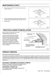
Using a cloth dampened with recessed light fixtures or some competitors' fan/light combinations. Panasonic fans and fan/light combination units do not create enough ambient heat to ensure a minimum of flexible duct helps alignment and... Proper insulation around the fan to drywall. Caulk termination to locate the Panasonic Authorized Service Center nearest you.) PANASONIC CONSUMER ELECTRONICS COMPANY Division of Panasonic Corporation of Covers. Fig. 12 PRODUCT SERVICE Warning Concerning Removal of North America, One Panasonic Way, Secaucus, NJ 07094 PANASONIC CANADA INC. 5770 Ambler...
Using a cloth dampened with recessed light fixtures or some competitors' fan/light combinations. Panasonic fans and fan/light combination units do not create enough ambient heat to ensure a minimum of flexible duct helps alignment and... Proper insulation around the fan to drywall. Caulk termination to locate the Panasonic Authorized Service Center nearest you.) PANASONIC CONSUMER ELECTRONICS COMPANY Division of Panasonic Corporation of Covers. Fig. 12 PRODUCT SERVICE Warning Concerning Removal of North America, One Panasonic Way, Secaucus, NJ 07094 PANASONIC CANADA INC. 5770 Ambler...
