Installation Instructions
Page 1
Please read these instructions carefully before attempting to installation 8 Product Service 8 Table of Contents Supplied Accessories 2 Description 2 Wiring Diagram 2 Dimensions 3 Specifications 3 Unpacking 3 General Safety Information 4 Installation I (Suspended Ceiling) 5 Installation II (Wooden Header Installation) 6 InstallationIII (In Existing Construction) 7 Maintenance 7-8 Practical guide to install, operate or service the Panasonic Ventilating Fan. INSTALLATION INSTRUCTIONS Ventilating Fan FV-20VQ3 FV-30VQ3 FV-40VQ3 Panasonid READ AND SAVE THESE...
Please read these instructions carefully before attempting to installation 8 Product Service 8 Table of Contents Supplied Accessories 2 Description 2 Wiring Diagram 2 Dimensions 3 Specifications 3 Unpacking 3 General Safety Information 4 Installation I (Suspended Ceiling) 5 Installation II (Wooden Header Installation) 6 InstallationIII (In Existing Construction) 7 Maintenance 7-8 Practical guide to install, operate or service the Panasonic Ventilating Fan. INSTALLATION INSTRUCTIONS Ventilating Fan FV-20VQ3 FV-30VQ3 FV-40VQ3 Panasonid READ AND SAVE THESE...
Installation Instructions
Page 2
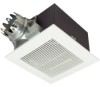
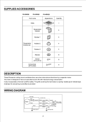
... 4 Rubber 1 4 103: Suspension Rubber 2 4 bracket set Rubber 3 0 4 Washer CD 8 Screw (ST4.2X12) 8 1) Long screw (ST4.2X20) El l' 6 DESCRIPTION These Panasonic ceiling mount ventilation fans use a low noise sirocco fan driven by a capacitor motor. It also incorporates a thermal-cutoff for preventing counterflow is provided. A damper for safety. WIRING DIAGRAM Motor Fan body Red White Black Junction box Capacitor White White Black Black Green Green Green Neutral Switch Power supply Live AC120V 60Hz (not included) Earth ground>. The grille covering the...
... 4 Rubber 1 4 103: Suspension Rubber 2 4 bracket set Rubber 3 0 4 Washer CD 8 Screw (ST4.2X12) 8 1) Long screw (ST4.2X20) El l' 6 DESCRIPTION These Panasonic ceiling mount ventilation fans use a low noise sirocco fan driven by a capacitor motor. It also incorporates a thermal-cutoff for preventing counterflow is provided. A damper for safety. WIRING DIAGRAM Motor Fan body Red White Black Junction box Capacitor White White Black Black Green Green Green Neutral Switch Power supply Live AC120V 60Hz (not included) Earth ground>. The grille covering the...
Installation Instructions
Page 3
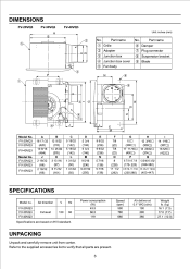
... Unpack and carefully remove unit from carton. F L M Model No. Air direction V Hz FV-20VQ3 FV-30VQ3 FV-40VQ3 Exhaust 120 60 Specifications are present. 3 Part name 0 Grille © Adapter ® Junction box © Junction box cover © Fan body No. Part name © Damper 0 Plug connector ® Suspension bracket 0 Blade N 6 O 4 7 9 _ I 14 1/16O (357O) 16 5/8O (422O) SPECIFICATIONS Model no. Refer to the supplied accessories list to verify that all parts are based...
... Unpack and carefully remove unit from carton. F L M Model No. Air direction V Hz FV-20VQ3 FV-30VQ3 FV-40VQ3 Exhaust 120 60 Specifications are present. 3 Part name 0 Grille © Adapter ® Junction box © Junction box cover © Fan body No. Part name © Damper 0 Plug connector ® Suspension bracket 0 Blade N 6 O 4 7 9 _ I 14 1/16O (357O) 16 5/8O (422O) SPECIFICATIONS Model no. Refer to the supplied accessories list to verify that all parts are based...
Installation Instructions
Page 4
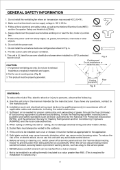
..., it can cause motor humming noise. B. E. Solid state controls may exceed 40°C (104°F). 2. Make sure that the electric service supply voltage is UL listed for Heating Refrigeration and Air Conditioning Engineers (ASHRAE) and the local code authorities. A. 8. For general ventilating use to the service panel. F. Protect the power cord from being switched on or near the fan, motor or junction box. 5. Prohibition 9. This...
..., it can cause motor humming noise. B. E. Solid state controls may exceed 40°C (104°F). 2. Make sure that the electric service supply voltage is UL listed for Heating Refrigeration and Air Conditioning Engineers (ASHRAE) and the local code authorities. A. 8. For general ventilating use to the service panel. F. Protect the power cord from being switched on or near the fan, motor or junction box. 5. Prohibition 9. This...
Installation Instructions
Page 5
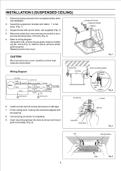
... rubber 1 to white; Refer to wiring diagram Using wire nuts, connect house power wires to ventilating fan wires (Fig. 3): black to receptacle. 9. Wiring Diagram Motor Fan body Red White Black Junction box Capacitor White White Black Black Neutral Switch Power supply Live AC120V 60Hz Green Green (not included) Green Earth ground>. 4 e Earth ground Earth ground Fig. Suspend body with fan opening. 8. Install circular duct (6 inches) and secure it with tape. 7. Replace junction box cover. 4 Screws (ST4.2X12) Suspension bracket Rubber 1 CAUTION Mount junction box cover...
... rubber 1 to white; Refer to wiring diagram Using wire nuts, connect house power wires to ventilating fan wires (Fig. 3): black to receptacle. 9. Wiring Diagram Motor Fan body Red White Black Junction box Capacitor White White Black Black Neutral Switch Power supply Live AC120V 60Hz Green Green (not included) Green Earth ground>. 4 e Earth ground Earth ground Fig. Suspend body with fan opening. 8. Install circular duct (6 inches) and secure it with tape. 7. Replace junction box cover. 4 Screws (ST4.2X12) Suspension bracket Rubber 1 CAUTION Mount junction box cover...
Installation Instructions
Page 6
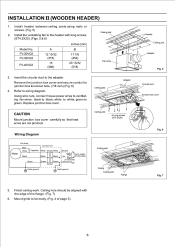
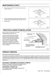
... Adapter CAUTION Mount junction box cover carefully so that lead wires are not pinched. INSTALLATION II (WOODEN HEADER) 1. Remove the junction box cover and secure conduit to green. green to junction box knockout hole. (7/8 inch) (Fig. 6) 4. Finish ceiling work. Refer to fan body. (Fig. 4 of the flange. (Fig. 7) 6. Mount grille to wiring diagram. Using wire nuts, connect house power wires to ventilating fan wires: black to the adapter. Ceiling joist 6 Long screws (ST4.2X20) Wiring Diagram Motor Fan body Red White Black Junction box Capacitor White White Black Black...
... Adapter CAUTION Mount junction box cover carefully so that lead wires are not pinched. INSTALLATION II (WOODEN HEADER) 1. Remove the junction box cover and secure conduit to green. green to junction box knockout hole. (7/8 inch) (Fig. 6) 4. Finish ceiling work. Refer to fan body. (Fig. 4 of the flange. (Fig. 7) 6. Mount grille to wiring diagram. Using wire nuts, connect house power wires to ventilating fan wires: black to the adapter. Ceiling joist 6 Long screws (ST4.2X20) Wiring Diagram Motor Fan body Red White Black Junction box Capacitor White White Black Black...
Installation Instructions
Page 7
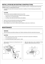
... obstruction or interference). Plan suitable location for cleaning the ventilating fan. 2. CAUTION 1. Remove grille. (Squeeze mounting spring and pull 2. Take the following precautions before working on unit. Do not soak resin parts in Installation II. Routine maintenace of the fan must be done and that : 1. No wiring or other such chemicals for fan body (next to enter motor. 3. Wiring can be done every year...
... obstruction or interference). Plan suitable location for cleaning the ventilating fan. 2. CAUTION 1. Remove grille. (Squeeze mounting spring and pull 2. Take the following precautions before working on unit. Do not soak resin parts in Installation II. Routine maintenace of the fan must be done and that : 1. No wiring or other such chemicals for fan body (next to enter motor. 3. Wiring can be done every year...
Installation Instructions
Page 8
...). No service information is a common problem with kitchen detergent, remove any dirt from fan body using a vacuum cleaner. (Fig. 10) 4. Your product is designed and manufactured to duct. 2-3 ft straight run before elbow. Replace grille. Dryer-hood type vent with new cloth. (Fig. 11) 5. Short piece of Covers. Using a cloth dampened with recessed light fixtures or some competitors' fan/light combinations. Panasonic fans and fan/light combination units...
...). No service information is a common problem with kitchen detergent, remove any dirt from fan body using a vacuum cleaner. (Fig. 10) 4. Your product is designed and manufactured to duct. 2-3 ft straight run before elbow. Replace grille. Dryer-hood type vent with new cloth. (Fig. 11) 5. Short piece of Covers. Using a cloth dampened with recessed light fixtures or some competitors' fan/light combinations. Panasonic fans and fan/light combination units...


