Installation Instructions
Page 1
... Header ) Installation VI( In Existing Construction ) Maintenance Practical Guide to comply with instructions could result in personal injury and/or property damage. INSTALLATION INSTRUCTIONS Ventilating Fan FV-05VQ3 FV-08VQ3 FV-11VQ3 FV-15VQ4 Panasonid READ AND SAVE THESE INSTRUCTIONS. Failure to Installation Product Service 2 2 2 3 4 4 4-5 6-8 8-9 10 10-11 12 12 13...
... Header ) Installation VI( In Existing Construction ) Maintenance Practical Guide to comply with instructions could result in personal injury and/or property damage. INSTALLATION INSTRUCTIONS Ventilating Fan FV-05VQ3 FV-08VQ3 FV-11VQ3 FV-15VQ4 Panasonid READ AND SAVE THESE INSTRUCTIONS. Failure to Installation Product Service 2 2 2 3 4 4 4-5 6-8 8-9 10 10-11 12 12 13...
Installation Instructions
Page 2
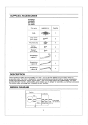
... Red Junction box Capacitor Motor White I Suspension bracket II -- - ' 1 Suspension bracket III 1 DESCRIPTION These Panasonic ceiling mount ventilation fans use a sirocco fan with reduced energy consumption. The double orifice technology and the sirocco fan are patented. Double orifice technology is a spring-loaded, quick-release type. The grille covering the main body is used to...
... Red Junction box Capacitor Motor White I Suspension bracket II -- - ' 1 Suspension bracket III 1 DESCRIPTION These Panasonic ceiling mount ventilation fans use a sirocco fan with reduced energy consumption. The double orifice technology and the sirocco fan are patented. Double orifice technology is a spring-loaded, quick-release type. The grille covering the main body is used to...
Installation Instructions
Page 3
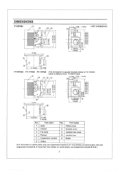
DIMENSIONS FV-05VQ3 11 R'. ,0 . . Part name 1 Grille 2 Adaptor 3 Fan body 4 Damper 5 Suspension bracket 6 Orifice No. 7 8 9 ' 10 11 Part name Orifice cover Bracket cover Junction box cover Junction box Blade (For 16 inches on center ...
DIMENSIONS FV-05VQ3 11 R'. ,0 . . Part name 1 Grille 2 Adaptor 3 Fan body 4 Damper 5 Suspension bracket 6 Orifice No. 7 8 9 ' 10 11 Part name Orifice cover Bracket cover Junction box cover Junction box Blade (For 16 inches on center ...
Installation Instructions
Page 4
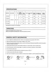
SPECIFICATIONS Duct Model No. Air direction V Hz diameter Noise Power consumption Speed Air deliver at (inches) (sones) (W) (tr/min) 0.1" WG(cfm) Weight lb.(kg) FV-05VQ3 4
SPECIFICATIONS Duct Model No. Air direction V Hz diameter Noise Power consumption Speed Air deliver at (inches) (sones) (W) (tr/min) 0.1" WG(cfm) Weight lb.(kg) FV-05VQ3 4
Installation Instructions
Page 5
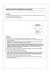
... cannot be vented to prevent backdrafting. Do not use to the manufacturer. B WARNING: To reduce the risk of fuel burning equipment to the outdoors. E. Ducted fans must be reached from being switched on accidentally.
... cannot be vented to prevent backdrafting. Do not use to the manufacturer. B WARNING: To reduce the risk of fuel burning equipment to the outdoors. E. Ducted fans must be reached from being switched on accidentally.
Installation Instructions
Page 6
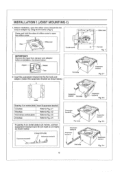
... screw IMPORTANT: Remove the tape from damper and adaptor before installation. Damper Tape 2. Insert the suspension bracket into the fan body and adaptor. (Select the suspension bracket as shown below) A .1 a Fan body a CI F I~ Joists Spacing A on center joists Insert Suspension bracket 12 inches Refer to Fig. 2-1 16... 2-4 If spacing A on center joists is 24 inches, connect suspension bracket II and DI (C4 mark to open the orifice cover, Secure the fan body to adaptor by using thumb screw. (Fig.1) Press and hold the claw of orifice cover to C4 mark) as shown below : Adaptor - ...
... screw IMPORTANT: Remove the tape from damper and adaptor before installation. Damper Tape 2. Insert the suspension bracket into the fan body and adaptor. (Select the suspension bracket as shown below) A .1 a Fan body a CI F I~ Joists Spacing A on center joists Insert Suspension bracket 12 inches Refer to Fig. 2-1 16... 2-4 If spacing A on center joists is 24 inches, connect suspension bracket II and DI (C4 mark to open the orifice cover, Secure the fan body to adaptor by using thumb screw. (Fig.1) Press and hold the claw of orifice cover to C4 mark) as shown below : Adaptor - ...
Installation Instructions
Page 7
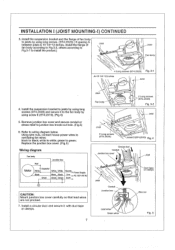
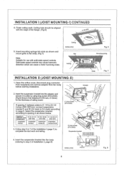
... knock-out hole. (Fig.5) 6. Install the suspension bracket to joists by using long screws (ST4.2X20) and secure it with duct tape or clamps. 7 Joist 0 Fan body 2 Long screws (ST4.2X20) Fig. 3-2 Joist Joist 2 Long screws (ST4.2X20) 0 0 screw II (ST4.2X10) Fig. 4 Circular duct Conduit Junction box ...or clamps Wire nut Lead wires Green wires Fig. 5 green to white; white to green; Install a circular duct and secure it to the fan body by using screw II (ST4.2X10). (Fig.4) 5. INSTALLATION I (JOIST MOUNTING-I) CONTINUED 3. Install the suspension bracket and the flange of...
... knock-out hole. (Fig.5) 6. Install the suspension bracket to joists by using long screws (ST4.2X20) and secure it with duct tape or clamps. 7 Joist 0 Fan body 2 Long screws (ST4.2X20) Fig. 3-2 Joist Joist 2 Long screws (ST4.2X20) 0 0 screw II (ST4.2X10) Fig. 4 Circular duct Conduit Junction box ...or clamps Wire nut Lead wires Green wires Fig. 5 green to white; white to green; Install a circular duct and secure it to the fan body by using screw II (ST4.2X10). (Fig.4) 5. INSTALLATION I (JOIST MOUNTING-I) CONTINUED 3. Install the suspension bracket and the flange of...
Installation Instructions
Page 8
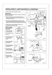
...1/4-23 1/2 ( 540-597 ) A inches (mm) 7/8 (21,6) Fig. 8 8 Open the orifice cover, disconnect plug connector from receptacle and remove adaptor from fan body before starting installation. 2. Spacing A Joi is 21 1/4 to 23 1/2 inches (540-597mm), connect suspension bracket II and DI (C4 mark to C4 mark) ...6mm) for use with the edge of ceiling board. Insert the suspension bracket into slots as shown below. Insert mounting springs into fan body (refering to fan body. (Fig.7) Note: Suitable for the thickness of the flange. (Fig.6) 0 ipe (2-15) 9. Solid-state speed controls...
...1/4-23 1/2 ( 540-597 ) A inches (mm) 7/8 (21,6) Fig. 8 8 Open the orifice cover, disconnect plug connector from receptacle and remove adaptor from fan body before starting installation. 2. Spacing A Joi is 21 1/4 to 23 1/2 inches (540-597mm), connect suspension bracket II and DI (C4 mark to C4 mark) ...6mm) for use with the edge of ceiling board. Insert the suspension bracket into slots as shown below. Insert mounting springs into fan body (refering to fan body. (Fig.7) Note: Suitable for the thickness of the flange. (Fig.6) 0 ipe (2-15) 9. Solid-state speed controls...
Installation Instructions
Page 9
... Fig.12-4 2 Long screws (ST4.2X20) Joist Fig. 11 9 Blower Joist Conduit Junction box cover Duct tape or clamps Circular duct 0 Fan body Slots Joist Adaptor claws Fig. 9 4. Follow step 8 to joists by using long screw (ST4.2X20). (Fig.11) 7. Insert....12-4) and plug connector to complete the installation work. Insert the blower into Fan body 9 joists. (Fig.9) 5. When mounting body and blower separately 1. Secure the adaptor to fan body by using thumb screw. (Fig.10) Fan body 0 6, Secure the fan body to 9 of page 8. INSTALLATION II ( JOIST MOUNTING-II ) CONTINUED ...
... Fig.12-4 2 Long screws (ST4.2X20) Joist Fig. 11 9 Blower Joist Conduit Junction box cover Duct tape or clamps Circular duct 0 Fan body Slots Joist Adaptor claws Fig. 9 4. Follow step 8 to joists by using long screw (ST4.2X20). (Fig.11) 7. Insert....12-4) and plug connector to complete the installation work. Insert the blower into Fan body 9 joists. (Fig.9) 5. When mounting body and blower separately 1. Secure the adaptor to fan body by using thumb screw. (Fig.10) Fan body 0 6, Secure the fan body to 9 of page 8. INSTALLATION II ( JOIST MOUNTING-II ) CONTINUED ...

Installation Instructions
Page 10
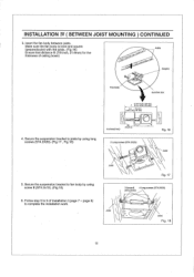
... IV ( BETWEEN JOIST MOUNTING ) 1. Insert the suspension bracket into the bracket cover of • adaptor side and the back of the fan body. (Fig.15) (select the suspension bracket according to the frame hole.) 3. Before installation, open the orifice cover. Connect the suspension bracket ...III to fan body. (Fig.13) (Select the hole by using thumb screw. (Fig.1 of 16 inches and 19.2 inches page 6) horizental Joist Suspension bracket...
... IV ( BETWEEN JOIST MOUNTING ) 1. Insert the suspension bracket into the bracket cover of • adaptor side and the back of the fan body. (Fig.15) (select the suspension bracket according to the frame hole.) 3. Before installation, open the orifice cover. Connect the suspension bracket ...III to fan body. (Fig.13) (Select the hole by using thumb screw. (Fig.1 of 16 inches and 19.2 inches page 6) horizental Joist Suspension bracket...
Installation Instructions
Page 11
...2x10). (Fig.18) 6. Joist .• • Fig. 17 2 Screw 11 4 Long screws (ST4.2X20) (ST4,2X10) Joist Joist Fig. 18 11 Adaptor Fan body Junction box 13 1/4-15 3/4 (336-400) A 16 1/2-16 3/4 (419-4B0) 3-5 ( 76-126 ) 5 4/5-7 4/5 148-198) 4. Secure the suspension... 2 Long screws (ST4.2X20) Fig. 16 Joist 5. INSTALLATION IV ( BETWEEN JOIST MOUNTING ) CONTINUED 3. page 8) to 9 of ceiling board. Make sure the fan body is level and square (perpendicular) with the joists. (Fig.16) Joists Ensure that distance B (7/8 inch, 21.6mm) for the thickness of installation I (page...
...2x10). (Fig.18) 6. Joist .• • Fig. 17 2 Screw 11 4 Long screws (ST4.2X20) (ST4,2X10) Joist Joist Fig. 18 11 Adaptor Fan body Junction box 13 1/4-15 3/4 (336-400) A 16 1/2-16 3/4 (419-4B0) 3-5 ( 76-126 ) 5 4/5-7 4/5 148-198) 4. Secure the suspension... 2 Long screws (ST4.2X20) Fig. 16 Joist 5. INSTALLATION IV ( BETWEEN JOIST MOUNTING ) CONTINUED 3. page 8) to 9 of ceiling board. Make sure the fan body is level and square (perpendicular) with the joists. (Fig.16) Joists Ensure that distance B (7/8 inch, 21.6mm) for the thickness of installation I (page...

Installation Instructions
Page 12
... CONSTRUCTION ) 1. CAUTION: Check area above the planning installation location or existing ducting and wiring. (1) To install the fan body, follow the procedures described in an existing building requires an accessible area (attic or crawl space) above planning installation...First, remove ceiling section according to 9 of page 8. (6) Install fan body. 2. Secure the fan body to be run to Fig.6 of joist page 6) 2. INSTALLATION V ( WOODEN HEADER 1. Installation from accessible area above fan location. (1) Inspect duct work shown in existing construction. Before installation...
... CONSTRUCTION ) 1. CAUTION: Check area above the planning installation location or existing ducting and wiring. (1) To install the fan body, follow the procedures described in an existing building requires an accessible area (attic or crawl space) above planning installation...First, remove ceiling section according to 9 of page 8. (6) Install fan body. 2. Secure the fan body to be run to Fig.6 of joist page 6) 2. INSTALLATION V ( WOODEN HEADER 1. Installation from accessible area above fan location. (1) Inspect duct work shown in existing construction. Before installation...
Installation Instructions
Page 13
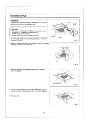
... spring and pull down carefully.) (Fig.21) Gloves Grille 2. Using a cloth dampened with kitchen detergent, remove any other such chemicals for cleaning the ventilating fan. 2. Replace grille. Do not damp water to motor. 3. Wash and clean grille. (Use non-abrasive kitchen detergent, wipe dry with new cloth. (...Fig.24) 5. Remove dust and dirt from fan body. CAUTION: 1, Never use petrol, benzene, thinner or any dirt from fan body using a vacuum cleaner. (Fig.23) 4. Vacuum cleaner 13 Fig. 22 Fig. 23 Fig. 24 Do ...
... spring and pull down carefully.) (Fig.21) Gloves Grille 2. Using a cloth dampened with kitchen detergent, remove any other such chemicals for cleaning the ventilating fan. 2. Replace grille. Do not damp water to motor. 3. Wash and clean grille. (Use non-abrasive kitchen detergent, wipe dry with new cloth. (...Fig.24) 5. Remove dust and dirt from fan body. CAUTION: 1, Never use petrol, benzene, thinner or any dirt from fan body using a vacuum cleaner. (Fig.23) 4. Vacuum cleaner 13 Fig. 22 Fig. 23 Fig. 24 Do ...
Installation Instructions
Page 14
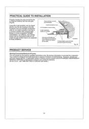
... INSTALLATION Properly insulate the area around the fan to duct. 2-3 ft straight run before elbow. In attic installation, caulk box to Customer call center.) 14 However, should be serviced by qualified technicians only. Panasonic fans and fan/light combination units do not create enough ...ambient heat to be placed directly over the fan housing in the attic. No service information is a common problem with backdraft flap...
... INSTALLATION Properly insulate the area around the fan to duct. 2-3 ft straight run before elbow. In attic installation, caulk box to Customer call center.) 14 However, should be serviced by qualified technicians only. Panasonic fans and fan/light combination units do not create enough ...ambient heat to be placed directly over the fan housing in the attic. No service information is a common problem with backdraft flap...
