Installation Instructions
Page 1
Failure to install, operate or service the Panasonic Ventilating Fan. INSTALLATION INSTRUCTIONS Ventilating Fan FV-05VQ3 FV-08VQ3 FV-11VQ3 FV-15VQ4 Panasonid READ AND SAVE THESE INSTRUCTIONS. Please read these instructions carefully before attempting to comply with instructions could result in personal injury and/or property damage. Please retain this booklet for future reference. Table of Contents Supplied Accessories Description Wiring diagram Dimensions Specifications Unpacking...
Failure to install, operate or service the Panasonic Ventilating Fan. INSTALLATION INSTRUCTIONS Ventilating Fan FV-05VQ3 FV-08VQ3 FV-11VQ3 FV-15VQ4 Panasonid READ AND SAVE THESE INSTRUCTIONS. Please read these instructions carefully before attempting to comply with instructions could result in personal injury and/or property damage. Please retain this booklet for future reference. Table of Contents Supplied Accessories Description Wiring diagram Dimensions Specifications Unpacking...
Installation Instructions
Page 2
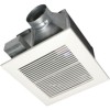
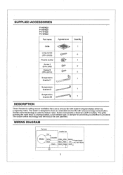
... 1 bracket I White White NeutraI > Power Supply Black Black Black Live >AC120V60 Hz Green Green Green Earth 2 The double orifice technology and the sirocco fan are patented. The grille covering the main body is used to have an extended service life with dolphin-shaped blades driven by a capacitor motor. A damper for safety. WIRING DIAGRAM Fan body Red Junction box Capacitor Motor White I Suspension bracket II -- - ' 1 Suspension bracket III 1 DESCRIPTION These Panasonic ceiling mount ventilation fans use a sirocco fan...
... 1 bracket I White White NeutraI > Power Supply Black Black Black Live >AC120V60 Hz Green Green Green Earth 2 The double orifice technology and the sirocco fan are patented. The grille covering the main body is used to have an extended service life with dolphin-shaped blades driven by a capacitor motor. A damper for safety. WIRING DIAGRAM Fan body Red Junction box Capacitor Motor White I Suspension bracket II -- - ' 1 Suspension bracket III 1 DESCRIPTION These Panasonic ceiling mount ventilation fans use a sirocco fan...
Installation Instructions
Page 3
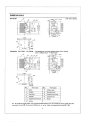
Part name 1 Grille 2 Adaptor 3 Fan body 4 Damper 5 Suspension bracket 6 Orifice No. 7 8 9 ' 10 11 Part name Orifice cover Bracket cover Junction box cover Junction box Blade (For 16 inches on center joists, only use suspension bracket II & 3 DIMENSIONS FV-05VQ3 11 R'. ,0 . . CO CO et2- .a- .c.s.i co 13 (330) 10 8 3 1 2 (90) r 1 (26) 1 (26 5 1 3/4 (46) Unit: inches(mm) 2 5 1/8 (130) 4 7 7/8 (200) 3 10 1/4 (261) 3 1/2 (90) FV-08VQ3 FV-11VQ3 FV-15VQ4 RD...
Part name 1 Grille 2 Adaptor 3 Fan body 4 Damper 5 Suspension bracket 6 Orifice No. 7 8 9 ' 10 11 Part name Orifice cover Bracket cover Junction box cover Junction box Blade (For 16 inches on center joists, only use suspension bracket II & 3 DIMENSIONS FV-05VQ3 11 R'. ,0 . . CO CO et2- .a- .c.s.i co 13 (330) 10 8 3 1 2 (90) r 1 (26) 1 (26 5 1 3/4 (46) Unit: inches(mm) 2 5 1/8 (130) 4 7 7/8 (200) 3 10 1/4 (261) 3 1/2 (90) FV-08VQ3 FV-11VQ3 FV-15VQ4 RD...
Installation Instructions
Page 4
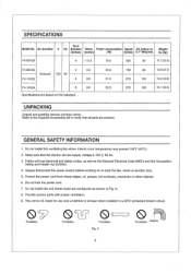
Air direction V Hz diameter Noise Power consumption Speed Air deliver at (inches) (sones) (W) (tr/min) 0.1" WG(cfm) Weight lb.(kg) FV-05VQ3 4 SPECIFICATIONS Duct Model No.
Air direction V Hz diameter Noise Power consumption Speed Air deliver at (inches) (sones) (W) (tr/min) 0.1" WG(cfm) Weight lb.(kg) FV-05VQ3 4 SPECIFICATIONS Duct Model No.
Installation Instructions
Page 5
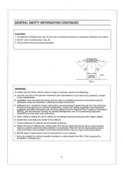
... use in cooking area. (Fig .B) 3. D. F. G. I . i r---i Cooking Floor equipment / Fig. If you have any questions, contact to persons, observe the following; C. Sufficient air is required for installation in accordance with all applicable codes and standards, including fire-rated construction. E. Before servicing or cleaning unit, switch power off at service panel and lock the service disconnecting means to prevent power from a tub or shower. H. NEVER place a switch...
... use in cooking area. (Fig .B) 3. D. F. G. I . i r---i Cooking Floor equipment / Fig. If you have any questions, contact to persons, observe the following; C. Sufficient air is required for installation in accordance with all applicable codes and standards, including fire-rated construction. E. Before servicing or cleaning unit, switch power off at service panel and lock the service disconnecting means to prevent power from a tub or shower. H. NEVER place a switch...
Installation Instructions
Page 6
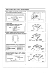
... 24 inches, connect suspension bracket II and DI (C4 mark to open the orifice cover. Before installation, open the orifice cover, Secure the fan body to adaptor by using thumb screw. (Fig.1) Press and hold the claw of orifice cover to C4 mark) as shown below : Adaptor - - As shown below : Suspension bracketIII 2 Screw I (ST4.2X8) Suspension bracket If Suspension bracket I Fan body Suspension a bracket HI Fan...
... 24 inches, connect suspension bracket II and DI (C4 mark to open the orifice cover. Before installation, open the orifice cover, Secure the fan body to adaptor by using thumb screw. (Fig.1) Press and hold the claw of orifice cover to C4 mark) as shown below : Adaptor - - As shown below : Suspension bracketIII 2 Screw I (ST4.2X8) Suspension bracket If Suspension bracket I Fan body Suspension a bracket HI Fan...
Installation Instructions
Page 7
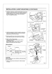
Refer to black; Replace the junction box cover. (Fig.5) Wiring diagram Fan body Red Junction box Motor Capacitor White" White White Neutra-l > Power Supply Black kBlac Black Live >AC 120V 60 Hz Green Green Green Earth CAUTION: Mount junction box cover carefully so that lead wires are not pinched. 7. Using wire nuts, connect house power wires to ventilating fan wires: black to wiring diagram below. Install a circular duct and secure it to the fan body by using long screws. (ST4.2X20) ( If spacing A between...
Refer to black; Replace the junction box cover. (Fig.5) Wiring diagram Fan body Red Junction box Motor Capacitor White" White White Neutra-l > Power Supply Black kBlac Black Live >AC 120V 60 Hz Green Green Green Earth CAUTION: Mount junction box cover carefully so that lead wires are not pinched. 7. Using wire nuts, connect house power wires to ventilating fan wires: black to wiring diagram below. Install a circular duct and secure it to the fan body by using long screws. (ST4.2X20) ( If spacing A between...
Installation Instructions
Page 8
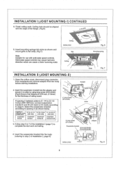
...), connect suspension bracket II and DI (C4 mark to C4 mark) according to page 6. Follow step 5 to 7 of ceiling board. Insert the suspension bracket into slots as shown below. Solid-state speed controls may cause harmonic distortion which can cause a motor humming noise. 0 / Ceiling inches (mm) Slot Ceiling Fig. 6 Mounting spring Grille Fig. 7 INSTALLATION II (JOIST MOUNTING-II) 1. INSTALLATION I (JOIST MOUNTING-I (page 7) to complete the duct work . Ceiling hole...
...), connect suspension bracket II and DI (C4 mark to C4 mark) according to page 6. Follow step 5 to 7 of ceiling board. Insert the suspension bracket into slots as shown below. Solid-state speed controls may cause harmonic distortion which can cause a motor humming noise. 0 / Ceiling inches (mm) Slot Ceiling Fig. 6 Mounting spring Grille Fig. 7 INSTALLATION II (JOIST MOUNTING-II) 1. INSTALLATION I (JOIST MOUNTING-I (page 7) to complete the duct work . Ceiling hole...
Installation Instructions
Page 9
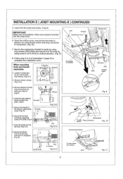
... by using thumb screw. (Fig.10) Fan body 0 6, Secure the fan body to complete the installation work. Insert the blower into Fan body 9 joists. (Fig.9) 5. Open the orifice cover, secure the fan body to adaptor by using thumb screw and plug connector to receptacle. (Fig.10) 7, Secure the suspension bracket to joists by using long screws (ST4.2X20) and secure it to joists as in vertical direction...
... by using thumb screw. (Fig.10) Fan body 0 6, Secure the fan body to complete the installation work. Insert the blower into Fan body 9 joists. (Fig.9) 5. Open the orifice cover, secure the fan body to adaptor by using thumb screw and plug connector to receptacle. (Fig.10) 7, Secure the suspension bracket to joists by using long screws (ST4.2X20) and secure it to joists as in vertical direction...

Installation Instructions
Page 10
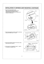
... the frame hole.) 3. Connect the suspension bracket III to fan body. (Fig.13) (Select the hole by checking I -joist. 1. Suspension bracket III Screw 11 (ST4.2X10) 0 Fig. 13 0 I 19.2 Inches vertical joist Fig. 15 10 Before installation, open the orifice cover. Secure the fan body to adaptor by using thumb screw. (Fig.1 of 16 inches and 19.2 inches page 6) horizental Joist Suspension bracket M 19.2 Inches vertical joist...
... the frame hole.) 3. Connect the suspension bracket III to fan body. (Fig.13) (Select the hole by checking I -joist. 1. Suspension bracket III Screw 11 (ST4.2X10) 0 Fig. 13 0 I 19.2 Inches vertical joist Fig. 15 10 Before installation, open the orifice cover. Secure the fan body to adaptor by using thumb screw. (Fig.1 of 16 inches and 19.2 inches page 6) horizental Joist Suspension bracket M 19.2 Inches vertical joist...
Installation Instructions
Page 11
... , Fig.18) inches(mm) B 7/8 (21,6) 2 Long screws (ST4.2X20) Fig. 16 Joist 5. Insert the fan body between joists. Joist .• • Fig. 17 2 Screw 11 4 Long screws (ST4.2X20) (ST4,2X10) Joist Joist Fig. 18 11 page 8) to fan body by using screw II (ST4.2x10). (Fig.18) 6. Secure the suspension bracket to complete the installation work. INSTALLATION IV ( BETWEEN JOIST MOUNTING ) CONTINUED...
... , Fig.18) inches(mm) B 7/8 (21,6) 2 Long screws (ST4.2X20) Fig. 16 Joist 5. Insert the fan body between joists. Joist .• • Fig. 17 2 Screw 11 4 Long screws (ST4.2X20) (ST4,2X10) Joist Joist Fig. 18 11 page 8) to fan body by using screw II (ST4.2x10). (Fig.18) 6. Secure the suspension bracket to complete the installation work. INSTALLATION IV ( BETWEEN JOIST MOUNTING ) CONTINUED...

Installation Instructions
Page 12
... by using nails or screws. 3. Installation from accessible area above fan location. (1) Inspect duct work and wiring before proceeding with installation work shown in an existing building requires an accessible area (attic or crawl space) above planning installation location to be done and that : 1. Before installation, open the orifice cover. Follow steps 5 to Fig.6 of page 8. (6) Install fan body. 2. Installing the fan body in installation II. (5) First, remove ceiling section...
... by using nails or screws. 3. Installation from accessible area above fan location. (1) Inspect duct work and wiring before proceeding with installation work shown in an existing building requires an accessible area (attic or crawl space) above planning installation location to be done and that : 1. Before installation, open the orifice cover. Follow steps 5 to Fig.6 of page 8. (6) Install fan body. 2. Installing the fan body in installation II. (5) First, remove ceiling section...
Installation Instructions
Page 13
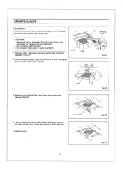
...: Disconnect power source before working on unit. Remove dust and dirt from fan body. Do not soak resin parts in water over 60°C. 1. Using a cloth dampened with new cloth. (Fig.24) 5. Routine maintenance must be done every year. Wipe dry with kitchen detergent, remove any other such chemicals for cleaning the ventilating fan. 2. Remove grille. (Squeeze mounting spring and pull down carefully...
...: Disconnect power source before working on unit. Remove dust and dirt from fan body. Do not soak resin parts in water over 60°C. 1. Using a cloth dampened with new cloth. (Fig.24) 5. Routine maintenance must be done every year. Wipe dry with kitchen detergent, remove any other such chemicals for cleaning the ventilating fan. 2. Remove grille. (Squeeze mounting spring and pull down carefully...
Installation Instructions
Page 14
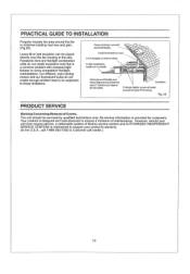
... product is maintained to support your product's warranty. (In the U.S.A., call center.) 14 Panasonic fans and fan/light combination units do not create enough ambient heat to be serviced by qualified technicians only. Our efficient, cool-running motors and our fluorescent bulbs do not create excessive heat that is provided for customers. Fig. 25 PRODUCT SERVICE Warning Concerning Removal of Covers.
... product is maintained to support your product's warranty. (In the U.S.A., call center.) 14 Panasonic fans and fan/light combination units do not create enough ambient heat to be serviced by qualified technicians only. Our efficient, cool-running motors and our fluorescent bulbs do not create excessive heat that is provided for customers. Fig. 25 PRODUCT SERVICE Warning Concerning Removal of Covers.
Installation Instructions
Page 15
PANASONIC CONSUMER ELECTRONICS COMPANY Division of Panasonic Corporation of North America, One Panasonic Way, Secaucus, NJ 07094 PANASONIC CANADA INC. 5770 Ambler Driver, Mississauga, ON L4W 2T3 www.panasonic.com X1204-8189 08VQ34020G
PANASONIC CONSUMER ELECTRONICS COMPANY Division of Panasonic Corporation of North America, One Panasonic Way, Secaucus, NJ 07094 PANASONIC CANADA INC. 5770 Ambler Driver, Mississauga, ON L4W 2T3 www.panasonic.com X1204-8189 08VQ34020G


