Operating Instructions
Page 1
Operating Instructions DLPTM Based Projector Commercial Use PT-D5600U Model No. TQBJ 0200 PT-D5600UL PT-DW5000U PT-DW5000UL Read these instructions completely before operating this unit.
Operating Instructions DLPTM Based Projector Commercial Use PT-D5600U Model No. TQBJ 0200 PT-D5600UL PT-DW5000U PT-DW5000UL Read these instructions completely before operating this unit.

Operating Instructions
Page 2
The serial number of your Panasonic DLPTM based projector. Model number: PT-D5600U/PT-D5600UL/PT-DW5000U/PT-DW5000UL Serial number: IMPORTANT SAFETY NOTICE WARNING: TO REDUCE THE RISK OF FIRE OR ELECTRIC SHOCK, DO NOT EXPOSE THIS PRODUCT TO RAIN OR ... Do not defeat the purpose of important operating and maintenance (servicing) instructions in case service is intended to alert the user to persons. Dear Panasonic Customer: This instruction booklet provides all the necessary operating information that you will only fit a grounding-type power outlet. WARNING RISK OF ELECTRIC SHOCK....
The serial number of your Panasonic DLPTM based projector. Model number: PT-D5600U/PT-D5600UL/PT-DW5000U/PT-DW5000UL Serial number: IMPORTANT SAFETY NOTICE WARNING: TO REDUCE THE RISK OF FIRE OR ELECTRIC SHOCK, DO NOT EXPOSE THIS PRODUCT TO RAIN OR ... Do not defeat the purpose of important operating and maintenance (servicing) instructions in case service is intended to alert the user to persons. Dear Panasonic Customer: This instruction booklet provides all the necessary operating information that you will only fit a grounding-type power outlet. WARNING RISK OF ELECTRIC SHOCK....
Operating Instructions
Page 4
... with regard to safety 5 Accessories 7 Precautions on handling 8 Name and function of parts 9 Remote control 9 Front and side of the projector 11 Rear view of the main unit/Controls on rear panel ..........12 Side-mounted connection terminals 13 Using the remote control unit 14 Loading dry... cells 14 Effective range of remote control operation 14 Setting projector ID number to the left or right............25 Automatic adjustment (AUTO SETUP 26 Using the FREEZE function 26 Using the SHUTTER function...
... with regard to safety 5 Accessories 7 Precautions on handling 8 Name and function of parts 9 Remote control 9 Front and side of the projector 11 Rear view of the main unit/Controls on rear panel ..........12 Side-mounted connection terminals 13 Using the remote control unit 14 Loading dry... cells 14 Effective range of remote control operation 14 Setting projector ID number to the left or right............25 Automatic adjustment (AUTO SETUP 26 Using the FREEZE function 26 Using the SHUTTER function...

Operating Instructions
Page 5
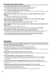
... wall outlet and wipe it in fire or electric shocks. • Contact an Authorized Service Center for repairs. • Do not attempt to repair the projector yourself, as this condition may result in a place which are coming loose from the wall. Do not handle the power cord plug with wet hands... any modifications to it, place it near any inspection, adjustment and repair work (such as ceiling suspension) should only be carried out by using the projector for an extended period of it or wrap it into water or let it may cause injury. • The lamp unit has high internal pressure...
... wall outlet and wipe it in fire or electric shocks. • Contact an Authorized Service Center for repairs. • Do not attempt to repair the projector yourself, as this condition may result in a place which are coming loose from the wall. Do not handle the power cord plug with wet hands... any modifications to it, place it near any inspection, adjustment and repair work (such as ceiling suspension) should only be carried out by using the projector for an extended period of it or wrap it into water or let it may cause injury. • The lamp unit has high internal pressure...
Operating Instructions
Page 6
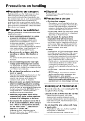
...; If any metal objects or flammable objects into water or fire. • Failure to observe this may result. • Do not use the projector for a prolonged period of time. 6 Do not short-circuit, heat or disassemble the battery or place it away from the reach of children. ...foreign objects into contact with metallic objects such as doing so can result in injury. Further, stacking one hour before moving the projector. • Moving the projector with cables still attached can cause death by suffocation if swallowed. • If the battery is pulled, the cord will become...
...; If any metal objects or flammable objects into water or fire. • Failure to observe this may result. • Do not use the projector for a prolonged period of time. 6 Do not short-circuit, heat or disassemble the battery or place it away from the reach of children. ...foreign objects into contact with metallic objects such as doing so can result in injury. Further, stacking one hour before moving the projector. • Moving the projector with cables still attached can cause death by suffocation if swallowed. • If the battery is pulled, the cord will become...
Operating Instructions
Page 7
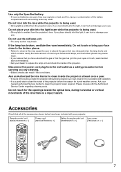
...; It is not done. Do not place your nearest Authorized Service Center to replace the lamp unit and check the inside of the projector. Please discuss with the Authorized Service Center regarding cleaning costs. Do not touch or bring your face close to the broken pieces. &#...8226; The lamp section may result. If you look into this may cause the user to observe this light, it can hurt or damage your projector. Remote control unit [N2QAYA000005 x 1] Power cord [K2CG3FZ00008 x 1] Battery for the openings beside the optical lens, during horizontal or vertical movements of...
...; It is not done. Do not place your nearest Authorized Service Center to replace the lamp unit and check the inside of the projector. Please discuss with the Authorized Service Center regarding cleaning costs. Do not touch or bring your face close to the broken pieces. &#...8226; The lamp section may result. If you look into this may cause the user to observe this light, it can hurt or damage your projector. Remote control unit [N2QAYA000005 x 1] Power cord [K2CG3FZ00008 x 1] Battery for the openings beside the optical lens, during horizontal or vertical movements of...
Operating Instructions
Page 8
... may be operated continuously round the clock, consult your dealer concerning the alternating lamp operation function (lamp changer function). Do not place the projector over 2 700 m (8 881.5') above sea level, consult your hands away from the receptacle before cleaning. When using it over 2 700... are transmitted from a source of driving power and others or mounted in which triggers the protection circuit, turning off dust. If the projector is used hours. • The life cycle of a mercury lamp varies according to observe the following characteristics: • It may increase...
... may be operated continuously round the clock, consult your dealer concerning the alternating lamp operation function (lamp changer function). Do not place the projector over 2 700 m (8 881.5') above sea level, consult your hands away from the receptacle before cleaning. When using it over 2 700... are transmitted from a source of driving power and others or mounted in which triggers the protection circuit, turning off dust. If the projector is used hours. • The life cycle of a mercury lamp varies according to observe the following characteristics: • It may increase...
Operating Instructions
Page 9
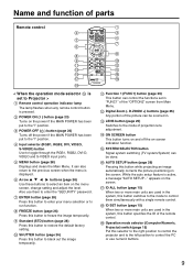
... auto setup feature is active, a message "AUTO SETUP..." SHUTTER button (page 26) Press this selector to the right position to control the projector and to the left position to the mode of projection lens adjustment. LENS button (page 25) Switches to control the PC or use them ...to control them simultaneously with a single remote control. Operation mode selector (Computer/Numeric, Projector) switch (page 15) Put this button to the "l" position. It can control the functions set to select an item on the menu screen, change...
... auto setup feature is active, a message "AUTO SETUP..." SHUTTER button (page 26) Press this selector to the right position to control the projector and to the left position to the mode of projection lens adjustment. LENS button (page 25) Switches to control the PC or use them ...to control them simultaneously with a single remote control. Operation mode selector (Computer/Numeric, Projector) switch (page 15) Put this button to the "l" position. It can control the functions set to select an item on the menu screen, change...
Operating Instructions
Page 10
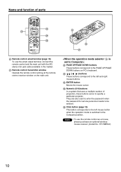
... to the left and right mouse buttons. They are also used to enter the password when the password for service personnel needs to specify a particular projector. Click button (page 15) This button corresponds to the Computer position. Name and function of...
... to the left and right mouse buttons. They are also used to enter the password when the password for service personnel needs to specify a particular projector. Click button (page 15) This button corresponds to the Computer position. Name and function of...
Operating Instructions
Page 11
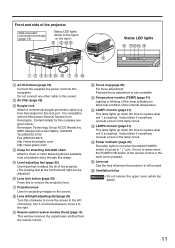
.... LAMP2 monitor (page 41) This lamp lights up when the time to replace lamp unit 1 is also available. Lens cap Cap the lens whenever the projector is left ; Temperature monitor (TEMP) (page 41) Lighting or blinking of this lamp indicates an abnormal condition of the... turns to this clamp. Contact details for attaching anti-theft chain Attach a chain or other cable to green when the POWER ON button of the projector. (The leveling feet at the front left /right adjusting dial (page 25) Turn this lock port. Powered focus adjustment is reached. Lens left and right...
.... LAMP2 monitor (page 41) This lamp lights up when the time to replace lamp unit 1 is also available. Lens cap Cap the lens whenever the projector is left ; Temperature monitor (TEMP) (page 41) Lighting or blinking of this lamp indicates an abnormal condition of the... turns to this clamp. Contact details for attaching anti-theft chain Attach a chain or other cable to green when the POWER ON button of the projector. (The leveling feet at the front left /right adjusting dial (page 25) Turn this lock port. Powered focus adjustment is reached. Lens left and right...
Operating Instructions
Page 12
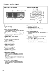
... 14) This also receives the signal beam coming from the remote control. POWER OFF ( ) button (page 24) Turns off "O" the main power applied to the projector. Name and function of parts Rear view of the main unit Controls on rear panel Controls on -screen display (OSD) selection menu can also return...
... 14) This also receives the signal beam coming from the remote control. POWER OFF ( ) button (page 24) Turns off "O" the main power applied to the projector. Name and function of parts Rear view of the main unit Controls on rear panel Controls on -screen display (OSD) selection menu can also return...

Operating Instructions
Page 13
... LAN VIDEO IN terminal (page 22) An input terminal for video signals. (BNC) S-VIDEO IN terminal (page 22) An input terminal for controlling the projector from the PC. (10Base-T/100Base-TX compliant) LAN terminal (10Base-T/100Base-TX) Connect LAN cable. RGB 1 input (RGB 1 IN) terminal (page 22...interface for S-video signals. (MIN4-pin DIN) This terminal complies with S1 signals and automatically toggles between 16:9 and 4:3 according to control the projector from your PC. (D-SUB 9-pin female) SERIAL OUT terminal (pages 22, 39) The signal applied to the serial input terminal appears at this...
... LAN VIDEO IN terminal (page 22) An input terminal for video signals. (BNC) S-VIDEO IN terminal (page 22) An input terminal for controlling the projector from the PC. (10Base-T/100Base-TX compliant) LAN terminal (10Base-T/100Base-TX) Connect LAN cable. RGB 1 input (RGB 1 IN) terminal (page 22...interface for S-video signals. (MIN4-pin DIN) This terminal complies with S1 signals and automatically toggles between 16:9 and 4:3 according to control the projector from your PC. (D-SUB 9-pin female) SERIAL OUT terminal (pages 22, 39) The signal applied to the serial input terminal appears at this...

Operating Instructions
Page 14
...730; (Front) (Rear) Remote 15˚ control 15˚ [Top view] 15˚ [Side view] 15˚ Figure 1 Remote control Screen Projector Attention • Do not drop the remote control unit. • Do not expose remote control unit to the optical loss by screen reflection. • ... function properly if an object is approx. 7 meters from the beam receiver on the projector (figure 1). Accessory type-AAA dry batteries (insert the negative side first). 3. Carefully site the projector so its remote control receiver windows will reflect commands back to intense light. 14 Remote 30...
...730; (Front) (Rear) Remote 15˚ control 15˚ [Top view] 15˚ [Side view] 15˚ Figure 1 Remote control Screen Projector Attention • Do not drop the remote control unit. • Do not expose remote control unit to the optical loss by screen reflection. • ... function properly if an object is approx. 7 meters from the beam receiver on the projector (figure 1). Accessory type-AAA dry batteries (insert the negative side first). 3. Carefully site the projector so its remote control receiver windows will reflect commands back to intense light. 14 Remote 30...

Operating Instructions
Page 15
... the Page Down button on the PC keyboard. • Click button This button can operate the remote control. The ID number of the projector is set even when no projector is "2.") Using the remote control as a PC mouse Left click ( ) button PAGE UP button ENTER button Right click ( ) button PAGE DOWN ... Put the knob to the Computer position. • ENTER button Pressing the front, rear, left and right edges of the operation mode selector switch to "Projector". However, if the ID ALL button is specified later. If the ID SET button is pressed, the ID number goes back to the one digit...
... the Page Down button on the PC keyboard. • Click button This button can operate the remote control. The ID number of the projector is set even when no projector is "2.") Using the remote control as a PC mouse Left click ( ) button PAGE UP button ENTER button Right click ( ) button PAGE DOWN ... Put the knob to the Computer position. • ENTER button Pressing the front, rear, left and right edges of the operation mode selector switch to "Projector". However, if the ID ALL button is specified later. If the ID SET button is pressed, the ID number goes back to the one digit...

Operating Instructions
Page 16
...-541 (16 37/64-21 19/64) SH SW 157 (6 3/16) 314 (12 23/64) (Default position) Installation geometry After the projector is roughly positioned, picture size and vertical picture positioning can be finely adjusted with a single remote control unit through the REMOTE1 IN/OUT terminal.... from the MAIN MENU) to choose the appropriate projection scheme (see page 35). Projection schemes Any of the cable is effective to use one projector on top of another projection unit. • Leave a clearance of projected image. Installation Using the remote control unit Using a wired remote control...
...-541 (16 37/64-21 19/64) SH SW 157 (6 3/16) 314 (12 23/64) (Default position) Installation geometry After the projector is roughly positioned, picture size and vertical picture positioning can be finely adjusted with a single remote control unit through the REMOTE1 IN/OUT terminal.... from the MAIN MENU) to choose the appropriate projection scheme (see page 35). Projection schemes Any of the cable is effective to use one projector on top of another projection unit. • Leave a clearance of projected image. Installation Using the remote control unit Using a wired remote control...
Operating Instructions
Page 21
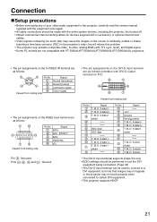
...digital signal. • Some PC models are not compatible with PT-D5600U/PT-D5600UL/PT-DW5000U/PT-DW5000UL projectors. • The pin assignments on the RGB2 input terminal are as follows: Viewed from mating side Pin...; The pin assignments on the DVI-D input terminal are as follows (interface with DVI-D output terminal on the screen to certain DVI equipment. • This projector supports HDCP. 21 M. M. S data 2 shield DDC clock DDC data Pin No. D. D. D. S data 1T. M. M. M. D. M. M. D. M. S data 0 shield T. S clock shield T. D. D. Signal +5 V ...
...digital signal. • Some PC models are not compatible with PT-D5600U/PT-D5600UL/PT-DW5000U/PT-DW5000UL projectors. • The pin assignments on the RGB2 input terminal are as follows: Viewed from mating side Pin...; The pin assignments on the DVI-D input terminal are as follows (interface with DVI-D output terminal on the screen to certain DVI equipment. • This projector supports HDCP. 21 M. M. S data 2 shield DDC clock DDC data Pin No. D. D. D. S data 1T. M. M. M. D. M. M. D. M. S data 0 shield T. S clock shield T. D. D. Signal +5 V ...

Operating Instructions
Page 22
... if the images are not disrupted, the white balance may be lost when the SYNC ON RGB signal is the case, connect a TBC between the projector and the video deck. • If nonstandard burst signals are connected, the image may be distorted. setting (see page 29), and adjust "W-BAL LOW".... are input. (Refer to page 34.) Example of connecting with PCs PC with a built-in time base corrector (TBC) or use a TBC between the projector and the video deck. • The EDID settings suited to the equipment connected must be used instead. Connection Example of connecting with AV products DVD...
... if the images are not disrupted, the white balance may be lost when the SYNC ON RGB signal is the case, connect a TBC between the projector and the video deck. • If nonstandard burst signals are connected, the image may be distorted. setting (see page 29), and adjust "W-BAL LOW".... are input. (Refer to page 34.) Example of connecting with PCs PC with a built-in time base corrector (TBC) or use a TBC between the projector and the video deck. • The EDID settings suited to the equipment connected must be used instead. Connection Example of connecting with AV products DVD...

Operating Instructions
Page 23
..., the control determines it as an abnormal condition and turns off and the image is powered up at least 30 minutes before powering up the projector. (Refer to adjust the image into focus. The temperature monitor (TEMP) lights during the warm-up period. Pressing buttons to page 25.) Remove... the screen. Projection R/PR G/Y B/PB SYNC/HD VD VIDEO IN S-VIDEO IN REMOTE 1 IN OUT RGB 1 IN REMOTE 2 IN SE Powering up the projector When using an optional lens, install a projection lens before any adjustments are made to the focus. 23 Press the " I " marked side of the lens to...
..., the control determines it as an abnormal condition and turns off and the image is powered up at least 30 minutes before powering up the projector. (Refer to adjust the image into focus. The temperature monitor (TEMP) lights during the warm-up period. Pressing buttons to page 25.) Remove... the screen. Projection R/PR G/Y B/PB SYNC/HD VD VIDEO IN S-VIDEO IN REMOTE 1 IN OUT RGB 1 IN REMOTE 2 IN SE Powering up the projector When using an optional lens, install a projection lens before any adjustments are made to the focus. 23 Press the " I " marked side of the lens to...

Operating Instructions
Page 24
To light up again. • While the cooling fan is accidentally disconnected immediately after the power cord is operating, do not place the projector inside a box or bag. • The operation time of the cooling fan will not light up orange. (The cooling fan keeps running.) ...Powering off the main power inadvertently, the projection lamp may shorten the lamp life. Press the " " marked side of cooling down after shutting off the projector Press the POWER OFF " " button. Select "OK" with the lamp in the process of the MAIN POWER switch to red (i.e., until the cooling...
To light up again. • While the cooling fan is accidentally disconnected immediately after the power cord is operating, do not place the projector inside a box or bag. • The operation time of the cooling fan will not light up orange. (The cooling fan keeps running.) ...Powering off the main power inadvertently, the projection lamp may shorten the lamp life. Press the " " marked side of cooling down after shutting off the projector Press the POWER OFF " " button. Select "OK" with the lamp in the process of the MAIN POWER switch to red (i.e., until the cooling...

Operating Instructions
Page 25
Press the LENS button on the remote control or on the screen can be adjusted while the projector is positioned appropriately in relation to the screen. How to install and remove the projection lens (optional) How to install the projection lens Align the ... Guide Guide groove Guide Lens signal contact Projection lens Attention • Turn the lens counterclockwise and confirm that the lens does not come off the projector's power. • Do not touch the lens signal contact. The screen moves toward the right The screen moves toward the left /right adjustment dial to...
Press the LENS button on the remote control or on the screen can be adjusted while the projector is positioned appropriately in relation to the screen. How to install and remove the projection lens (optional) How to install the projection lens Align the ... Guide Guide groove Guide Lens signal contact Projection lens Attention • Turn the lens counterclockwise and confirm that the lens does not come off the projector's power. • Do not touch the lens signal contact. The screen moves toward the right The screen moves toward the left /right adjustment dial to...


