Service Manual
Page 1
... Notebook Computer CF-73 This is the Service Manual for U.S.A. featured by product. LAN V: DVD-ROM Drive / Wireless LAN 5: Operation System D: Microsoft® Windows® 2000 K: Microsoft® Windows® XP Professional 6: Area M: Refer to above area table and Canada Model Number Reference The following areas. ORDER NO. CF-731 2 3 4 X 5 6 1: CPU type E: Intel® Pentium® M Processor 1.4 GHz 2: LCD type 3: 13.3-type TFT /XGA Color 3: HDD type / RAM size K: 40 GB / 256 MB 4: Drive / Modem - M ...for the following models are numbered...
... Notebook Computer CF-73 This is the Service Manual for U.S.A. featured by product. LAN V: DVD-ROM Drive / Wireless LAN 5: Operation System D: Microsoft® Windows® 2000 K: Microsoft® Windows® XP Professional 6: Area M: Refer to above area table and Canada Model Number Reference The following areas. ORDER NO. CF-731 2 3 4 X 5 6 1: CPU type E: Intel® Pentium® M Processor 1.4 GHz 2: LCD type 3: 13.3-type TFT /XGA Color 3: HDD type / RAM size K: 40 GB / 256 MB 4: Drive / Modem - M ...for the following models are numbered...

Service Manual
Page 9
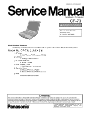
... Sound is output from Card Speakers built into the back panel of Parts Wireless LAN Antenna LCD Power Switch Before using the computer for the first time, carefully read the [LIMITED USE LICENSE AGREEMENT]. 2 Names and Functions of the LCD screen. DC-IN Jack DC IN 15.1-16.0 V Multimedia Pocket LED Indicators Power status Battery pack status Ventilation Hole This hole allows heat to the conditions, remove the seal. External Display Port Serial Port Use this port...
... Sound is output from Card Speakers built into the back panel of Parts Wireless LAN Antenna LCD Power Switch Before using the computer for the first time, carefully read the [LIMITED USE LICENSE AGREEMENT]. 2 Names and Functions of the LCD screen. DC-IN Jack DC IN 15.1-16.0 V Multimedia Pocket LED Indicators Power status Battery pack status Ventilation Hole This hole allows heat to the conditions, remove the seal. External Display Port Serial Port Use this port...
Service Manual
Page 10
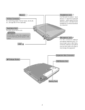
... Connector RAM Module Slot Battery Pack 7 Microphone Jack Use only a monaural condenser microphone (miniature jack). Using an input source other than a monaural condenser microphone may not allow audio to be input or may prevent proper ventilation. CAUTION Do not block or place the computer in a location that may damage the equipment. Modem I/O Box Connector For connecting printer, external mouse, keyboard, etc., through the I/O box (optional). Audio output from the internal...
... Connector RAM Module Slot Battery Pack 7 Microphone Jack Use only a monaural condenser microphone (miniature jack). Using an input source other than a monaural condenser microphone may not allow audio to be input or may prevent proper ventilation. CAUTION Do not block or place the computer in a location that may damage the equipment. Modem I/O Box Connector For connecting printer, external mouse, keyboard, etc., through the I/O box (optional). Audio output from the internal...
Service Manual
Page 15
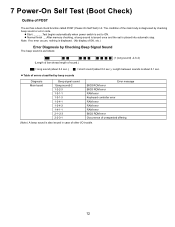
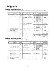
... sounds Diagnosis Main board Beep signal sound 1(long sound)-2 1-2-2-3 1-3-1-1 1-3-1-3 1-3-4-1 1-3-4-3 1-4-1-1 2-1-2-3 2-2-3-1 Error message BIOS ROM error BIOS ROM error RAM error Keyboard controller error RAM error RAM error RAM error BIOS ROM error Occurrence of unexpected offering (Note) A beep sound is also issued in it. z Normal finish .....After memory checking, a beep sound is issued once and the set is set has a boot check function called POST (Power-On Self Test) in case of other I/O trouble. 12 7 Power-On Self Test (Boot Check) Outline of POST The set to ON. z Start...
... sounds Diagnosis Main board Beep signal sound 1(long sound)-2 1-2-2-3 1-3-1-1 1-3-1-3 1-3-4-1 1-3-4-3 1-4-1-1 2-1-2-3 2-2-3-1 Error message BIOS ROM error BIOS ROM error RAM error Keyboard controller error RAM error RAM error RAM error BIOS ROM error Occurrence of unexpected offering (Note) A beep sound is also issued in it. z Normal finish .....After memory checking, a beep sound is issued once and the set is set has a boot check function called POST (Power-On Self Test) in case of other I/O trouble. 12 7 Power-On Self Test (Boot Check) Outline of POST The set to ON. z Start...
Service Manual
Page 16
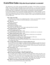
...Setup menus, reset the computer, enter Setup and install Setup defaults or correct the error. 0200 Failure Fixed Disk Fixed disk in CMOS. 8 List of Error Codes The following is a list of the messages that BIOS can also terminate POST and cause this error on keyboard. 0211 Keyboard error Keyboard not working. 0212 Keyboard Controller Failed Keyboard controller failed test. Others may indicate a problem with control of system board. 0270 Real time clock error Real-time clock fails BIOS test. May require replacing keyboard controller. 0213 Keyboard locked - Replace the battery...
...Setup menus, reset the computer, enter Setup and install Setup defaults or correct the error. 0200 Failure Fixed Disk Fixed disk in CMOS. 8 List of Error Codes The following is a list of the messages that BIOS can also terminate POST and cause this error on keyboard. 0211 Keyboard error Keyboard not working. 0212 Keyboard Controller Failed Keyboard controller failed test. Others may indicate a problem with control of system board. 0270 Real time clock error Real-time clock fails BIOS test. May require replacing keyboard controller. 0213 Keyboard locked - Replace the battery...
Service Manual
Page 17
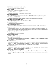
... information shown on either drive A: or drive C:. Cache disabled Contact Panasonic Technical Support. 02F0: CPU ID: CPU socket number for specified device. Allocation Error for: device Run ISA or EISA Configuration Utility to locate the address and display it on the screen. Each 1 (one) in System, Extended or Shadow memory. Enter Setup and see if fixed disk and drive A: are properly identified. If it cannot locate the address, it displays ????. A parity error indicates that some data...
... information shown on either drive A: or drive C:. Cache disabled Contact Panasonic Technical Support. 02F0: CPU ID: CPU socket number for specified device. Allocation Error for: device Run ISA or EISA Configuration Utility to locate the address and display it on the screen. Each 1 (one) in System, Extended or Shadow memory. Enter Setup and see if fixed disk and drive A: are properly identified. If it cannot locate the address, it displays ????. A parity error indicates that some data...
Service Manual
Page 18
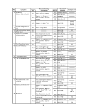
...(2/2) Make sure that connecting cables, connectors and AC adapter are not displayed. No. Result Source of problem YES Go to ON, check voltage on either side of Q699? procedures Result problem 1-1 Is 15V applied to ON. YES Go to No.1-3 NO Go to No.1-2 Component Q699 Before setting the power 1-3 switch to No.1-2 NO Improper setting Device for "Boot Up Drive", the system boots from...
...(2/2) Make sure that connecting cables, connectors and AC adapter are not displayed. No. Result Source of problem YES Go to ON, check voltage on either side of Q699? procedures Result problem 1-1 Is 15V applied to ON. YES Go to No.1-3 NO Go to No.1-2 Component Q699 Before setting the power 1-3 switch to No.1-2 NO Improper setting Device for "Boot Up Drive", the system boots from...
Service Manual
Page 19
...-2 YES Battery NO Main PCB Configuration YES Go to No.12-2 NO Go to No.12-4 YES FDD NO Go to No.12-3 YES HDD NO Go to 8-1 normal if the expansion card is not updating 14 Memory size/data error 15 PCI failure Troubleshooting No. Symptom 4 No Sound Volume does not work. 5 Default configuration in SETUP correct the problem? 14-1 Replace the expansion RAM card. Replace the FDD...
...-2 YES Battery NO Main PCB Configuration YES Go to No.12-2 NO Go to No.12-4 YES FDD NO Go to No.12-3 YES HDD NO Go to 8-1 normal if the expansion card is not updating 14 Memory size/data error 15 PCI failure Troubleshooting No. Symptom 4 No Sound Volume does not work. 5 Default configuration in SETUP correct the problem? 14-1 Replace the expansion RAM card. Replace the FDD...
Service Manual
Page 21
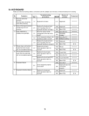
...? 9.4 KEYBOARD Make sure that connecting cables, connectors and AC adapter are not loose or disconnected prior to No.3-3 NO Software setting Replace the keyboard and YES Keyboard 3-3 see if inputting from the function. Troubleshooting No. Replace the touch pad. Key top does not spring back after pressing. YES Go to are not accepted properly. normal? NO Main PCB 4 Mouse does not function. Inputs from the track ball 5-1 Does operation...
...? 9.4 KEYBOARD Make sure that connecting cables, connectors and AC adapter are not loose or disconnected prior to No.3-3 NO Software setting Replace the keyboard and YES Keyboard 3-3 see if inputting from the function. Troubleshooting No. Replace the touch pad. Key top does not spring back after pressing. YES Go to are not accepted properly. normal? NO Main PCB 4 Mouse does not function. Inputs from the track ball 5-1 Does operation...
Service Manual
Page 22
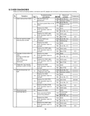
.... 1-4 Replace the HDD cable. 1-4 Does operation return to normal? YES HDD cable NO Main PCB Replace the HDD. 4-1 Does operation return to normal? No. YES HDD cable NO Main PCB 2-1 Has the HDD been formatted? YES HDD NO Main PCB 5-1 Has the HDD been configured in HDC or HDD. 5 Access lamp does not light. 6 Abnormal sound. 7 Hard disk failure Troubleshooting Source of No. YES Main PCB NO HDD cable 6-1 Replace the HDD. 7-1 Does executing FDISK correct the problem...
.... 1-4 Replace the HDD cable. 1-4 Does operation return to normal? YES HDD cable NO Main PCB Replace the HDD. 4-1 Does operation return to normal? No. YES HDD cable NO Main PCB 2-1 Has the HDD been formatted? YES HDD NO Main PCB 5-1 Has the HDD been configured in HDC or HDD. 5 Access lamp does not light. 6 Abnormal sound. 7 Hard disk failure Troubleshooting Source of No. YES Main PCB NO HDD cable 6-1 Replace the HDD. 7-1 Does executing FDISK correct the problem...
Service Manual
Page 23
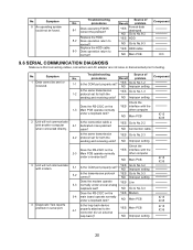
... Improper setting IC15 IC35 20 Troubleshooting Source of Result problem YES Format data destroyed NO Go to No.8-2 YES HDD NO Go to No.8-3 YES HDD cable NO Main PCB Component IC3 9.6 SERIAL COMMUNICATION DIAGNOSIS Make sure that connecting cables, connectors and AC adapter are not loose or disconnected prior to No.3-4 IC15 IC35 Does the RS-232C on the 3-4 main board operate normally...
... Improper setting IC15 IC35 20 Troubleshooting Source of Result problem YES Format data destroyed NO Go to No.8-2 YES HDD NO Go to No.8-3 YES HDD cable NO Main PCB Component IC3 9.6 SERIAL COMMUNICATION DIAGNOSIS Make sure that connecting cables, connectors and AC adapter are not loose or disconnected prior to No.3-4 IC15 IC35 Does the RS-232C on the 3-4 main board operate normally...

Service Manual
Page 24
... problem Replace the CD-ROM drive. YES CD-ROM drive 2-2 Does operation return to testing. NO Main PCB Replace the CD-ROM drive. YES Media NO CD-ROM drive Component LD1007 IC3 IC3 IC3 21 9.7 CD-ROM (DVD-ROM) Drive DIAGNOSIS Make sure that connecting cables, connectors and AC adapter are not loose or disconnected prior to normal? YES CD-ROM drive 3-1 Does operation return to normal? NO Go to No.1-2 Replace the LED PCB. 1-2 Does operation...
... problem Replace the CD-ROM drive. YES CD-ROM drive 2-2 Does operation return to testing. NO Main PCB Replace the CD-ROM drive. YES Media NO CD-ROM drive Component LD1007 IC3 IC3 IC3 21 9.7 CD-ROM (DVD-ROM) Drive DIAGNOSIS Make sure that connecting cables, connectors and AC adapter are not loose or disconnected prior to normal? YES CD-ROM drive 3-1 Does operation return to normal? NO Go to No.1-2 Replace the LED PCB. 1-2 Does operation...
Service Manual
Page 25
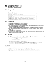
... user to the factory setting values by executing the "SETUP UTILITY" which can be invoked by F2 key at the POST. Preparation (1) Connect the computer to the IO BOX (CF-VEBU03). (2) Connect the AC Adapter and External Equipments. (3) The System Setup should be set to skip the previous password and disable the password. 22 Equipment (1) Test Computer 1 unit (2) IO BOX (CF-VEBU03 1 unit (3) External Floppy Disk Drive (USB Port 1 unit (4) AC Adapter 1 pc. (5) External...
... user to the factory setting values by executing the "SETUP UTILITY" which can be invoked by F2 key at the POST. Preparation (1) Connect the computer to the IO BOX (CF-VEBU03). (2) Connect the AC Adapter and External Equipments. (3) The System Setup should be set to skip the previous password and disable the password. 22 Equipment (1) Test Computer 1 unit (2) IO BOX (CF-VEBU03 1 unit (3) External Floppy Disk Drive (USB Port 1 unit (4) AC Adapter 1 pc. (5) External...
Service Manual
Page 26
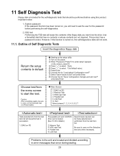
... power. 11 Self Diagnosis Test Floppy disk is turned on, the self-diagnostics tests will not work. 11.1. System password If the password function has been turned on the screen, press F2. Use a formatted disk that occur during testing. 23 However, if this product. Starting up the setup utility Turn on FD 2. When "Panasonic Press F2 to enter setup" appears on , you insert into the drive. Choose Yes for the password...
... power. 11 Self Diagnosis Test Floppy disk is turned on, the self-diagnostics tests will not work. 11.1. System password If the password function has been turned on the screen, press F2. Use a formatted disk that occur during testing. 23 However, if this product. Starting up the setup utility Turn on FD 2. When "Panasonic Press F2 to enter setup" appears on , you insert into the drive. Choose Yes for the password...
Service Manual
Page 27
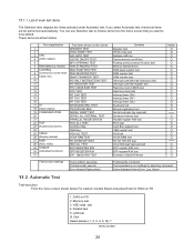
.../2 MOUSE REG 19 COMMUNICATION SERIAL WRAP TEST 20 SERIAL ALL INTERNAL TEST 21 PARALLEL REGISTER R/W 22 AUX PCIC ALL TEST 23 (Auxiliary functions) Card Bus Reg 24 USB Reg 25 VIDEO 26 (Display related) VGA ALL TEST SVGA RAM TEST 27 DISK FD WT/RD/WP TEST 28 (FDD, HDD) HDD ALL TEST 29 UNIQUE 30 (Individual functions) ECP REGISTER R/W EPP REGISTER R/W 31 EXT. menu screen...
.../2 MOUSE REG 19 COMMUNICATION SERIAL WRAP TEST 20 SERIAL ALL INTERNAL TEST 21 PARALLEL REGISTER R/W 22 AUX PCIC ALL TEST 23 (Auxiliary functions) Card Bus Reg 24 USB Reg 25 VIDEO 26 (Display related) VGA ALL TEST SVGA RAM TEST 27 DISK FD WT/RD/WP TEST 28 (FDD, HDD) HDD ALL TEST 29 UNIQUE 30 (Individual functions) ECP REGISTER R/W EPP REGISTER R/W 31 EXT. menu screen...
Service Manual
Page 28
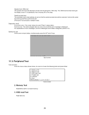
... screen shows the word "Pass" in large letters. HDD read Test Read test only. 25 The VESA test involves looking at the display to music and choosing OK or Not okay. Connect the serial loop back jig and then perform the test. (This test is not executed on default mode) Diagnostics result If no errors occur. If errors occur. LAN...
... screen shows the word "Pass" in large letters. HDD read Test Read test only. 25 The VESA test involves looking at the display to music and choosing OK or Not okay. Connect the serial loop back jig and then perform the test. (This test is not executed on default mode) Diagnostics result If no errors occur. If errors occur. LAN...
Service Manual
Page 29
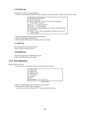
... key. 26 Choose Parallel test and press Enter. 4. Choose CD-ROM test and press Enter. 11.4. From the menu screen shown below . [Changing the setup utility] Turn on FD 2. When A: \DIAG appears, input "JDG_73" and press Enter. 3. When "Panasonic", "Press F2 to choose Mode. Connect the parallel loop back jig to default. 5. Choose LAN test and press Enter. (CD-ROM test) This tests the internal CD-ROM drive functions. DIAG on the power...
... key. 26 Choose Parallel test and press Enter. 4. Choose CD-ROM test and press Enter. 11.4. From the menu screen shown below . [Changing the setup utility] Turn on FD 2. When A: \DIAG appears, input "JDG_73" and press Enter. 3. When "Panasonic", "Press F2 to choose Mode. Connect the parallel loop back jig to default. 5. Choose LAN test and press Enter. (CD-ROM test) This tests the internal CD-ROM drive functions. DIAG on the power...

Service Manual
Page 31
... function Memory standard DMA page register DAM register DAM transfer test Interrupt controller Interrupt controller Real time clock CMOS Speaker Interrupt timer CH0 Interrupt timer CH1 Interrupt timer CH2 Keyboard Mouse Serial loop back (jig required) Serial port Parallel register PCIC Card Bus port USB port VGA SVGA RAM VESA mode FD write/read/write protection Only HDD lead selected Parallel port Parallel port Extension CMOS R/W test 28 Error Messages and Troubleshooting...
... function Memory standard DMA page register DAM register DAM transfer test Interrupt controller Interrupt controller Real time clock CMOS Speaker Interrupt timer CH0 Interrupt timer CH1 Interrupt timer CH2 Keyboard Mouse Serial loop back (jig required) Serial port Parallel register PCIC Card Bus port USB port VGA SVGA RAM VESA mode FD write/read/write protection Only HDD lead selected Parallel port Parallel port Extension CMOS R/W test 28 Error Messages and Troubleshooting...
Service Manual
Page 32
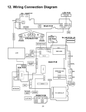
...Connection Diagram CN 1002 MIC JK 1000 HEADPHONE JK 1001 DC-IN JK 1002 CN 1001 CN 1006 SW 1001 REAR PCB LED PCB CN 1300 SW 1000 CN CN 1003 1005 CN 1000 INVERTER CN 1601 L C1N600 17C00N R CN 1701 SPEAKER PCB SPEAKER SPEAKER BATTERY PACK I/O CN 3001 I/O PCB CN 3000 FAN W-LAN PCB L/R LCD LAN JACK PORT... REPLICATOR CN 600 CN 18 CN 12 CN 7 CN 20 CN 2 RAM CARD VGA CN 5 CN 803 CN 802 CN 800 CN 801 VGA PCB DVD-ROM DRIVE CN 14 CN 4 MAIN PCB CN 19 WIRELESS LAN CARD CN 3 CN 9 CN 13 CN 15 KEYBOARD HDD CN 10 MODEM JACK FLAT PAD...
...Connection Diagram CN 1002 MIC JK 1000 HEADPHONE JK 1001 DC-IN JK 1002 CN 1001 CN 1006 SW 1001 REAR PCB LED PCB CN 1300 SW 1000 CN CN 1003 1005 CN 1000 INVERTER CN 1601 L C1N600 17C00N R CN 1701 SPEAKER PCB SPEAKER SPEAKER BATTERY PACK I/O CN 3001 I/O PCB CN 3000 FAN W-LAN PCB L/R LCD LAN JACK PORT... REPLICATOR CN 600 CN 18 CN 12 CN 7 CN 20 CN 2 RAM CARD VGA CN 5 CN 803 CN 802 CN 800 CN 801 VGA PCB DVD-ROM DRIVE CN 14 CN 4 MAIN PCB CN 19 WIRELESS LAN CARD CN 3 CN 9 CN 13 CN 15 KEYBOARD HDD CN 10 MODEM JACK FLAT PAD...
Service Manual
Page 42
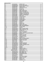
..., PAD BUTTON WATER PROOF 1 K 40 DFMD4044ZB PLATE, SP 2 K 41 DFMX0785ZA SHEET, INV CABLE 1 K 42 DFMX1079ZB CASE, INVERTER 1 K 43 DFHG1399XA-0 RUBBER, LCD LEG 2 K 44 DFHE0418ZA MAGNET, LID 1 K 45 DFKM8153ZA-0 ASS'Y LCD REAR CABINET 1 K 45-1 DFUQ0095ZA SPRING, LCD LATCH 1 K 45-2 DFDF3147ZA SHAFT, LCD LATCH 1 K 45-3 DFBH1167ZA HINGE, L 1 K 45-4 DFBH1168ZA HINGE, R 1 K 45-5 DFKE0706ZA-0 COVER, LCD W LAN 1 K 45-6 DFGB0106ZA-0 LABEL, PANASONIC 1 K 45-7 DFGX0396ZA-0 DUMMY, ANTENNA COVER...
..., PAD BUTTON WATER PROOF 1 K 40 DFMD4044ZB PLATE, SP 2 K 41 DFMX0785ZA SHEET, INV CABLE 1 K 42 DFMX1079ZB CASE, INVERTER 1 K 43 DFHG1399XA-0 RUBBER, LCD LEG 2 K 44 DFHE0418ZA MAGNET, LID 1 K 45 DFKM8153ZA-0 ASS'Y LCD REAR CABINET 1 K 45-1 DFUQ0095ZA SPRING, LCD LATCH 1 K 45-2 DFDF3147ZA SHAFT, LCD LATCH 1 K 45-3 DFBH1167ZA HINGE, L 1 K 45-4 DFBH1168ZA HINGE, R 1 K 45-5 DFKE0706ZA-0 COVER, LCD W LAN 1 K 45-6 DFGB0106ZA-0 LABEL, PANASONIC 1 K 45-7 DFGX0396ZA-0 DUMMY, ANTENNA COVER...


