
BTLH1760E User Guide
Page 3
ference in a particular instal- IMPORTANT SAFETY INSTRUCTIONS 1) Read these instructions. 2) Keep these instructions. 3) Heed all warnings. 4) Follow all servicing to provide reasonable protection against harmful inter- The user may cause harmful interference to which can radiate radio frequency energy, and if not installed and used , use only shielded interface cables when connecting to rain or moisture, does not operate normally, or has been dropped...
ference in a particular instal- IMPORTANT SAFETY INSTRUCTIONS 1) Read these instructions. 2) Keep these instructions. 3) Heed all warnings. 4) Follow all servicing to provide reasonable protection against harmful inter- The user may cause harmful interference to which can radiate radio frequency energy, and if not installed and used , use only shielded interface cables when connecting to rain or moisture, does not operate normally, or has been dropped...

BTLH1760E User Guide
Page 4
...; DO NOT REMOVE PANEL COVERS BY UNSCREWING THEM. For your safety, if you are a major cause of fatalities. To reduce the risk of the monitor could cause the monitor to the floor so that the installation is earthed or that it will not topple over. CAUTION: THE MAINS PLUG OF THE POWER SUPPLY CORD SHALL REMAIN READILY OPERABLE. USE AND STORE...
...; DO NOT REMOVE PANEL COVERS BY UNSCREWING THEM. For your safety, if you are a major cause of fatalities. To reduce the risk of the monitor could cause the monitor to the floor so that the installation is earthed or that it will not topple over. CAUTION: THE MAINS PLUG OF THE POWER SUPPLY CORD SHALL REMAIN READILY OPERABLE. USE AND STORE...
BTLH1760E User Guide
Page 6
... 7 Controls and Their Functions 8 Video monitor unit 8 Front panel 9 Rear panel 10 Power Supply 11 How to Use the On Screen Menu 12 User Data 16 Main Menu 17 Menu configuration 17 MARKER 18 Marker types 19 VIDEO CONFIG 20 SYSTEM CONFIG 22 FUNCTION 23 GPI 29 INPUT SELECT 30 AUDIO 32 DISPLAY SETUP 33 CONTROL 34 HOURMETER 34 REMOTE Specifications 36 How to precise specifications. Contents Read this unit including the mount...
... 7 Controls and Their Functions 8 Video monitor unit 8 Front panel 9 Rear panel 10 Power Supply 11 How to Use the On Screen Menu 12 User Data 16 Main Menu 17 Menu configuration 17 MARKER 18 Marker types 19 VIDEO CONFIG 20 SYSTEM CONFIG 22 FUNCTION 23 GPI 29 INPUT SELECT 30 AUDIO 32 DISPLAY SETUP 33 CONTROL 34 HOURMETER 34 REMOTE Specifications 36 How to precise specifications. Contents Read this unit including the mount...
BTLH1760E User Guide
Page 7
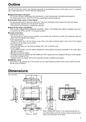
....0-inch wide LCD display panel. ■ High performance LCD panel This monitor achieves outstanding color reproduction, a wide viewing angle, and high-speed response. The double-speed drive in one pixel on the intended use . Outline The BT-LH1760 LCD monitor was designed especially for SDI input) of input signals. • Cross hatch overlay function Displays markers at regular vertical and horizontal intervals to facilitate composition. ■ REMOTE control Depending on the screen). • Time code display...
....0-inch wide LCD display panel. ■ High performance LCD panel This monitor achieves outstanding color reproduction, a wide viewing angle, and high-speed response. The double-speed drive in one pixel on the intended use . Outline The BT-LH1760 LCD monitor was designed especially for SDI input) of input signals. • Cross hatch overlay function Displays markers at regular vertical and horizontal intervals to facilitate composition. ■ REMOTE control Depending on the screen). • Time code display...

BTLH1760E User Guide
Page 9
...) Front panel POWER switch Switches the power supply ON/OFF. Speaker The speaker reproduces audio input from "YPBPR/RGB" in the "INPUT SELECT" menu (J page 30). FUNCTION4 : Confirms a menu item assigned to FUNCTION3. The settings are changed . Volume knob Turn this knob to FUNCTION5. * When the control lock is ON, the LED (green) lights up. VIDEO : Video input SDI1 : Serial digital interface input (HD/SD compatible) SDI2 : Serial digital interface input (HD/SD compatible) YPBPR/RGB : Analog component (YPBPR) or RGB input. Picture adjusting knob PHASE...
...) Front panel POWER switch Switches the power supply ON/OFF. Speaker The speaker reproduces audio input from "YPBPR/RGB" in the "INPUT SELECT" menu (J page 30). FUNCTION4 : Confirms a menu item assigned to FUNCTION3. The settings are changed . Volume knob Turn this knob to FUNCTION5. * When the control lock is ON, the LED (green) lights up. VIDEO : Video input SDI1 : Serial digital interface input (HD/SD compatible) SDI2 : Serial digital interface input (HD/SD compatible) YPBPR/RGB : Analog component (YPBPR) or RGB input. Picture adjusting knob PHASE...

BTLH1760E User Guide
Page 10
... DVI-D signal input terminal. Controls and Their Functions (continued) Rear panel 1 2 3 4 5 6 78 9 SDI (HD/SD) terminal (BNC) IN1 : This is the vertical synchronizing signal (VD) input terminal used when connecting to a PC RGB signal. Note that plugging in a daisy chain* pattern using the RGB signal, you can also connect the external synchronizing signal to the SYNC/HD terminal. When multiple monitors are connected in a pair of headphones to monitor the sound. * The sound volume and sound...
... DVI-D signal input terminal. Controls and Their Functions (continued) Rear panel 1 2 3 4 5 6 78 9 SDI (HD/SD) terminal (BNC) IN1 : This is the vertical synchronizing signal (VD) input terminal used when connecting to a PC RGB signal. Note that plugging in a daisy chain* pattern using the RGB signal, you can also connect the external synchronizing signal to the SYNC/HD terminal. When multiple monitors are connected in a pair of headphones to monitor the sound. * The sound volume and sound...

BTLH1760E User Guide
Page 11
... been removed or opened, do not use the correct polarity. Using the power cord hook and the screw, attach the power cord to external DC input. (When shipped from the factory, the power cover is up, and AC input is not longer than 2 m. Power Supply Connecting and fixing the power cord 1. A cable that is selected.) Power cover Power cord Power cord hook Screw 2. Connect the power cord to both the AC input and external DC input terminals. • Use a shielded DC cable that is accidentally connected to the monitor...
... been removed or opened, do not use the correct polarity. Using the power cord hook and the screw, attach the power cord to external DC input. (When shipped from the factory, the power cover is up, and AC input is not longer than 2 m. Power Supply Connecting and fixing the power cord 1. A cable that is selected.) Power cover Power cord Power cord hook Screw 2. Connect the power cord to both the AC input and external DC input terminals. • Use a shielded DC cable that is accidentally connected to the monitor...

BTLH1760E User Guide
Page 12
... on . Various indications (FILM mode) • This indicates that the format selected in the "INPUT SELECT" menu does not match the input signal. • "NO SIGNAL" appears if no signal is input. 3. Display status: PHASE, CHROMA, BRIGHT, CONTRAST or BACKLIGHT. Sharpness display • This is input. Input signal status 1. Note: The status of information: input signal status, picture adjusting knob status, sharpness display, FUNCTION display, audio level meter display, menu display, time code display and closed caption display. DVI-VIDEO/DVI-COMP. 2.
... on . Various indications (FILM mode) • This indicates that the format selected in the "INPUT SELECT" menu does not match the input signal. • "NO SIGNAL" appears if no signal is input. 3. Display status: PHASE, CHROMA, BRIGHT, CONTRAST or BACKLIGHT. Sharpness display • This is input. Input signal status 1. Note: The status of information: input signal status, picture adjusting knob status, sharpness display, FUNCTION display, audio level meter display, menu display, time code display and closed caption display. DVI-VIDEO/DVI-COMP. 2.

BTLH1760E User Guide
Page 20
... lower part of the screen during adjustment. The item display moves to the lower part of the screen during adjustment. Sets the aspect ratio for the selected input signal is displayed. under -scan and normal display. Selects type of outline correction edge. Color Monochrome * When ON, the CHROMA setting of the picture adjusting knob is fixed at the top left of the screen. 1) VIDEO system input (VIDEO) (the factory defaults are SHARPNESS MODE: LOW...
... lower part of the screen during adjustment. The item display moves to the lower part of the screen during adjustment. Sets the aspect ratio for the selected input signal is displayed. under -scan and normal display. Selects type of outline correction edge. Color Monochrome * When ON, the CHROMA setting of the picture adjusting knob is fixed at the top left of the screen. 1) VIDEO system input (VIDEO) (the factory defaults are SHARPNESS MODE: LOW...

BTLH1760E User Guide
Page 21
... "MODE1". in this monitor suppresses the delay to "WHITE BALANCE VAR3" (WB) adjustments. The factory default is suitable for checking interlace status. ■ WB adjustment mode Select "VAR1" to color temperature values selected under "COLOR TEMP." *1 Selecting "COLOR TEMP." "MODE2" performs IP conversion using inter-frame interpolation. Underlined values indicate factory defaults. and pressing [ENTER] after making a change, opens a confirmation screen. Main Menu (continued) IP mode "MODE1" performs IP conversion...
... "MODE1". in this monitor suppresses the delay to "WHITE BALANCE VAR3" (WB) adjustments. The factory default is suitable for checking interlace status. ■ WB adjustment mode Select "VAR1" to color temperature values selected under "COLOR TEMP." *1 Selecting "COLOR TEMP." "MODE2" performs IP conversion using inter-frame interpolation. Underlined values indicate factory defaults. and pressing [ENTER] after making a change, opens a confirmation screen. Main Menu (continued) IP mode "MODE1" performs IP conversion...
BTLH1760E User Guide
Page 22
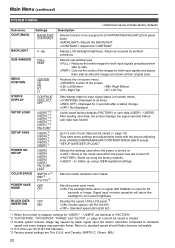
....709 standard. *5 Factory preset settings are The U.S.A. Adjusts LCD backlight brightness. Not displayed. Starts in the mode used when the power is input for "USER1" - After loading user data, the screen displays the signal selected before user data was last turned off. Starts up using the factory defaults. Sets the studio standard color shade. Selects sub-window type. Positions the on -screen menu). Displayed at their original size). Signal input or menu operation will return the backlight to be saved (J page 16). Main Menu (continued) SYSTEM...
....709 standard. *5 Factory preset settings are The U.S.A. Adjusts LCD backlight brightness. Not displayed. Starts in the mode used when the power is input for "USER1" - After loading user data, the screen displays the signal selected before user data was last turned off. Starts up using the factory defaults. Sets the studio standard color shade. Selects sub-window type. Positions the on -screen menu). Displayed at their original size). Signal input or menu operation will return the backlight to be saved (J page 16). Main Menu (continued) SYSTEM...

BTLH1760E User Guide
Page 23
... STANDARD Switches between "16:9" and "4:3."*1 Switches between color and monochrome. Positions the display of functions assigned to [FUNCTION1] - [FUNCTION5] (front panel buttons). Switches between "UNDER SCAN" and "NORMAL SCAN".*1 Sets the split-screen function.*1 The display changes in the following order. DELAY OFF J V DELAY J H DELAY J HV DELAY J DELAY OFF Performs auto setup for PC display. The display changes in PIXEL TO PIXEL mode. Turns the PIXEL TO PIXEL function On and Off. Use this...
... STANDARD Switches between "16:9" and "4:3."*1 Switches between color and monochrome. Positions the display of functions assigned to [FUNCTION1] - [FUNCTION5] (front panel buttons). Switches between "UNDER SCAN" and "NORMAL SCAN".*1 Sets the split-screen function.*1 The display changes in the following order. DELAY OFF J V DELAY J H DELAY J HV DELAY J DELAY OFF Performs auto setup for PC display. The display changes in PIXEL TO PIXEL mode. Turns the PIXEL TO PIXEL function On and Off. Use this...

BTLH1760E User Guide
Page 25
.... Use the "SUB WINDOW" setting (FULL, PART) in two as shown below to also display a second window (two sub-windows). Press the button ([FUNCTION1] to [FUNCTION5] (J page 23)) to which the SUB WINDOW function has been assigned. Each press of the button changes the display as follows: H blanking display J V blanking display J H and V blanking display J no blanking display. ■ "SUB WINDOW" Opening the "SUB WINDOW" function splits the screen (main window) in...
.... Use the "SUB WINDOW" setting (FULL, PART) in two as shown below to also display a second window (two sub-windows). Press the button ([FUNCTION1] to [FUNCTION5] (J page 23)) to which the SUB WINDOW function has been assigned. Each press of the button changes the display as follows: H blanking display J V blanking display J H and V blanking display J no blanking display. ■ "SUB WINDOW" Opening the "SUB WINDOW" function splits the screen (main window) in...
BTLH1760E User Guide
Page 30
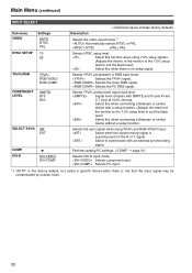
... this when connecting a Betacam or similar device without a setup function. Main Menu (continued) INPUT SELECT Sub menu VIDEO NTSC SETUP Settings AUTO NTSC PAL 75 00 YPBPR/RGB YPBPR RGB-VIDEO RGB-COMP. Underlined values indicate factory defaults. NTSC PAL Selects NTSC setup level. Selects the YPBPR signal. Selects the PC RGB signal. DVI-D DVI-VIDEO DVI-COMP. Selects YPBPR (component) or RGB input mode. Selects the sync signal when using 7.5% setup signals. (Adjusts the interior of the monitor to the 7.5% setup level to...
... this when connecting a Betacam or similar device without a setup function. Main Menu (continued) INPUT SELECT Sub menu VIDEO NTSC SETUP Settings AUTO NTSC PAL 75 00 YPBPR/RGB YPBPR RGB-VIDEO RGB-COMP. Underlined values indicate factory defaults. NTSC PAL Selects NTSC setup level. Selects the YPBPR signal. Selects the PC RGB signal. DVI-D DVI-VIDEO DVI-COMP. Selects YPBPR (component) or RGB input mode. Selects the sync signal when using 7.5% setup signals. (Adjusts the interior of the monitor to the 7.5% setup level to...

BTLH1760E User Guide
Page 34
... factory defaults. The "LOCAL ENABLE" setting determines operations in "OVER". 34 Disables all front panel operations. All controls except [INPUT SELECT] and the volume knob are available when the lock is engaged. The volume knob (J page 9, used during lock engagement. ) can be [MAIN MENU] MARKER Key mark *2 Only available when "REMOTE" is engaged. "XXXXXX": 262800H (about 30 years), 262800 or greater number results in lock mode. The picture adjusting...
... factory defaults. The "LOCAL ENABLE" setting determines operations in "OVER". 34 Disables all front panel operations. All controls except [INPUT SELECT] and the volume knob are available when the lock is engaged. The volume knob (J page 9, used during lock engagement. ) can be [MAIN MENU] MARKER Key mark *2 Only available when "REMOTE" is engaged. "XXXXXX": 262800H (about 30 years), 262800 or greater number results in lock mode. The picture adjusting...

BTLH1760E User Guide
Page 36
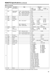
... GND changes from open (OFF). SDI2 INPUT SEL. FILM Switches between color and monochrome (MONO). (Disabled during PC signal input) Lights the red tally. Selects the SYNC when using YPBPR/RGB-VIDEO input. Switches the input line to the following terminals. GPI terminal GPI screen items correspond to SDI1. Turns the center marker display on other markers are displayed, this marker is selected under "YPBPR/RGB" in the "INPUT SELECT" menu. 36 Switches the input line...
... GND changes from open (OFF). SDI2 INPUT SEL. FILM Switches between color and monochrome (MONO). (Disabled during PC signal input) Lights the red tally. Selects the SYNC when using YPBPR/RGB-VIDEO input. Switches the input line to the following terminals. GPI terminal GPI screen items correspond to SDI1. Turns the center marker display on other markers are displayed, this marker is selected under "YPBPR/RGB" in the "INPUT SELECT" menu. 36 Switches the input line...

BTLH1760E User Guide
Page 38
... Input switch VPC 2 Image quality adjustment 3 OBO 4 OHV 5 VBL 6 DCH 7 DSD 8 ISM 9 IRF 10 ISM DMK Blue only HV Delay Backlight Cross hatch Status display Analog mode SELECT Sync DVI-D mode Marker settings 11 12 MGM MCT 13 VPC 14 15 MIP 16 OMO 17 MAS 18 MSC 19 MCO 20 MLE Gamma selection Color temperature settings Sharpness settings IP mode settings Monochrome settings SD aspect settings Scan settings Remote settings Remote operation settings Data...
... Input switch VPC 2 Image quality adjustment 3 OBO 4 OHV 5 VBL 6 DCH 7 DSD 8 ISM 9 IRF 10 ISM DMK Blue only HV Delay Backlight Cross hatch Status display Analog mode SELECT Sync DVI-D mode Marker settings 11 12 MGM MCT 13 VPC 14 15 MIP 16 OMO 17 MAS 18 MSC 19 MCO 20 MLE Gamma selection Color temperature settings Sharpness settings IP mode settings Monochrome settings SD aspect settings Scan settings Remote settings Remote operation settings Data...
BTLH1760E User Guide
Page 39
... × 768 (50 Hz) FF: UNSUPORT SIGNAL BT-LH1760 *1 When both 16:9 and 4:3 markers are displayed, the 16:9 marker state is returned. 39 QPC 2 Image quality adjustment CON : Contrast setting value BRI : Brightness setting value CRO : Chroma setting value 00-60 00-60 00-60 3 QBO 4 QBL 5 QCH Blue only Backlight Cross hatch PHA : Phase setting value 00-60 0: OFF 00-60...
... × 768 (50 Hz) FF: UNSUPORT SIGNAL BT-LH1760 *1 When both 16:9 and 4:3 markers are displayed, the 16:9 marker state is returned. 39 QPC 2 Image quality adjustment CON : Contrast setting value BRI : Brightness setting value CRO : Chroma setting value 00-60 00-60 00-60 3 QBO 4 QBL 5 QCH Blue only Backlight Cross hatch PHA : Phase setting value 00-60 0: OFF 00-60...
BTLH1760E User Guide
Page 41
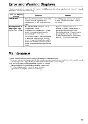
.... The "LOW VOLTAGE" indication flashes in the inverter that the external DC power supply input voltage has dropped below 11.0 V. Set the POWER switch to the off and the screen turns black. They could damage it back on the screen. This means that controls backlight brightness, the backlight goes off position and then set it with a fully charged battery pack. • Connect an external DC power supply providing 11.0 V or more...
.... The "LOW VOLTAGE" indication flashes in the inverter that the external DC power supply input voltage has dropped below 11.0 V. Set the POWER switch to the off and the screen turns black. They could damage it back on the screen. This means that controls backlight brightness, the backlight goes off position and then set it with a fully charged battery pack. • Connect an external DC power supply providing 11.0 V or more...
BTLH1760E User Guide
Page 42
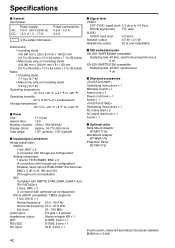
...; Signal level VIDEO EXT SYNC signal level: 0.3 Vp-p to 4.0 Vp-p HD/VD signal level: TTL level AUDIO AUDIO input level: 0.5 Vrms Speaker output: 0.5 W + 0.5 W Headphone output: 32 Ω, level adjustable ■ SDI embedded audio HD-SDI: SMPTE299M compatible Sampling rate: 48 kHz, synchronous/asynchronous 8 ch SD-SDI: SMPTE272M compatible Sampling rate: 48 kHz, synchronous 4 ch ■ Standard accessories Operationg instructions × 1 Warranty (Card) × 1 Power cord × 1 Power cord hook × 1 Screw × 1 Operationg instructions...
...; Signal level VIDEO EXT SYNC signal level: 0.3 Vp-p to 4.0 Vp-p HD/VD signal level: TTL level AUDIO AUDIO input level: 0.5 Vrms Speaker output: 0.5 W + 0.5 W Headphone output: 32 Ω, level adjustable ■ SDI embedded audio HD-SDI: SMPTE299M compatible Sampling rate: 48 kHz, synchronous/asynchronous 8 ch SD-SDI: SMPTE272M compatible Sampling rate: 48 kHz, synchronous 4 ch ■ Standard accessories Operationg instructions × 1 Warranty (Card) × 1 Power cord × 1 Power cord hook × 1 Screw × 1 Operationg instructions...


