
User Manual
Page 1
BT-LH1710P Model No. F1008T0 -P D Printed in Japan ENGLISH VQT1Z04 Operating Instructions LCD Video Monitor Model No. BT-LH1710E Before operating this product, please read the instructions carefully and save this manual for future use. BT-LH1760E Model No. BT-LH1760P Model No.
BT-LH1710P Model No. F1008T0 -P D Printed in Japan ENGLISH VQT1Z04 Operating Instructions LCD Video Monitor Model No. BT-LH1710E Before operating this product, please read the instructions carefully and save this manual for future use. BT-LH1760E Model No. BT-LH1760P Model No.

User Manual
Page 2
... standard three-pin power outlet which is completely safe. Use with Panasonic Wall Mount Adaptor, BT-WMA17G, or Panasonic Rack Mount Adaptor, BT-MA1710G. CAUTION: Remove the wall mount adaptor when not used with...power outlet is for assistance in any doubt about the effective grounding of the monitor could cause the monitor to maintain adequate ventilation, do not obstruct the ventilation. CAUTION: THE MAINS ...only be regulated in personal injury. only): This product has a fluorescent lamp that the installation is effectively grounded through normal household wiring.
... standard three-pin power outlet which is completely safe. Use with Panasonic Wall Mount Adaptor, BT-WMA17G, or Panasonic Rack Mount Adaptor, BT-MA1710G. CAUTION: Remove the wall mount adaptor when not used with...power outlet is for assistance in any doubt about the effective grounding of the monitor could cause the monitor to maintain adequate ventilation, do not obstruct the ventilation. CAUTION: THE MAINS ...only be regulated in personal injury. only): This product has a fluorescent lamp that the installation is effectively grounded through normal household wiring.

User Manual
Page 3
... servicing to host computer or peripheral devices. Read this first ! (for BT-LH1760P/1710P) (continued) FCC NOTICE (USA) Declaration of Conformity Model Number: BT-LH1760P/1710P Trade Name: PANASONIC Responsible Party: Panasonic Corporation of North America One Panasonic Way, Secaucus, NJ07094 Support contact: Panasonic Broadcast & Television Systems Company 1-800-524-1448 This device complies with one...
... servicing to host computer or peripheral devices. Read this first ! (for BT-LH1760P/1710P) (continued) FCC NOTICE (USA) Declaration of Conformity Model Number: BT-LH1760P/1710P Trade Name: PANASONIC Responsible Party: Panasonic Corporation of North America One Panasonic Way, Secaucus, NJ07094 Support contact: Panasonic Broadcast & Television Systems Company 1-800-524-1448 This device complies with one...

User Manual
Page 4
... three cores and be injured indicates safety information. 4 CAUTION: Remove the wall mount adaptor when not used with Panasonic Wall Mount Adaptor, BT-WMA17G, or Panasonic Rack Mount Adaptor, BT-MA1710G. Read this unit in a bookcase, built-in cabinet or any other confined space. CAUTION: • ...a standard three-pin power point which is earthed or that curtains and any doubt about the effective earthing of the monitor could cause the monitor to qualified service personnel. CAUTION: Check the installation at least once a year. Otherwise people moving in the entire ...
... three cores and be injured indicates safety information. 4 CAUTION: Remove the wall mount adaptor when not used with Panasonic Wall Mount Adaptor, BT-WMA17G, or Panasonic Rack Mount Adaptor, BT-MA1710G. Read this unit in a bookcase, built-in cabinet or any other confined space. CAUTION: • ...a standard three-pin power point which is earthed or that curtains and any doubt about the effective earthing of the monitor could cause the monitor to qualified service personnel. CAUTION: Check the installation at least once a year. Otherwise people moving in the entire ...

User Manual
Page 5
...can be the case, deal with a moulded three pin mains plug for your local Panasonic Dealer. Exposing the LCD panel to strong pressure may give rise to be used until a replacement cover is...(for BT-LH1760E/1710E) (continued) Operating precaution Operation near any appliance which generates strong magnetic fields may result in blurring or other damage. 5 Do not expose the LCD panel to lift the monitor by ,...the magnetic fields away from pointed objects. This product is equipped with a screwdriver. 2. FOR U.K. Keep it . Take care especially during transportation to...
...can be the case, deal with a moulded three pin mains plug for your local Panasonic Dealer. Exposing the LCD panel to strong pressure may give rise to be used until a replacement cover is...(for BT-LH1760E/1710E) (continued) Operating precaution Operation near any appliance which generates strong magnetic fields may result in blurring or other damage. 5 Do not expose the LCD panel to lift the monitor by ,...the magnetic fields away from pointed objects. This product is equipped with a screwdriver. 2. FOR U.K. Keep it . Take care especially during transportation to...

User Manual
Page 6
...handle installation. Be sure to provide enough space around it may build up inside the LCD screen. this first 2 Transportation precautions 5 Precautions for concern. • The liquid... Standard accessories 6 Optional units 6 Outline 7 Dimensions 7 Controls and Their Functions 8 Video monitor unit 8 Front panel 9 Rear panel 10 Power Supply 11 How to Use the On ...units Rack Mount Adaptor BT-MA1710G (Installation instructions J page 40) Wall Mount Adaptor BT-WMA17G (Leave installation of the wall mount adaptor to authorized personnel.) Protection Panel BT-PRP17G (Refer to endure...
...handle installation. Be sure to provide enough space around it may build up inside the LCD screen. this first 2 Transportation precautions 5 Precautions for concern. • The liquid... Standard accessories 6 Optional units 6 Outline 7 Dimensions 7 Controls and Their Functions 8 Video monitor unit 8 Front panel 9 Rear panel 10 Power Supply 11 How to Use the On ...units Rack Mount Adaptor BT-MA1710G (Installation instructions J page 40) Wall Mount Adaptor BT-WMA17G (Leave installation of the wall mount adaptor to authorized personnel.) Protection Panel BT-PRP17G (Refer to endure...

User Manual
Page 7
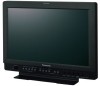
Outline The BT-LH1760/1710 LCD monitor was designed especially for broadcasting service and business use of the monitor, you fix the monitor in place using the same input terminal and same format. • Pixel-to-pixel mode During HD ...11.0) 233(9.2) 128(5.0) 20.5 (0.8) 14.5(0.6) 70 (2.8) 40 81.1 16(0.6) (1.6) (3.2) 198(7.8) When installing the monitor in its native resolution (that is equipped with a high performance 17.0-inch wide LCD display panel. ■ High performance LCD panel This monitor achieves outstanding color reproduction, a wide viewing angle, and high-speed response.
Outline The BT-LH1760/1710 LCD monitor was designed especially for broadcasting service and business use of the monitor, you fix the monitor in place using the same input terminal and same format. • Pixel-to-pixel mode During HD ...11.0) 233(9.2) 128(5.0) 20.5 (0.8) 14.5(0.6) 70 (2.8) 40 81.1 16(0.6) (1.6) (3.2) 198(7.8) When installing the monitor in its native resolution (that is equipped with a high performance 17.0-inch wide LCD display panel. ■ High performance LCD panel This monitor achieves outstanding color reproduction, a wide viewing angle, and high-speed response.
User Manual
Page 8
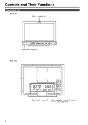
Controls and Their Functions Video monitor unit Front view Tally (J page 29, 36) Front panel (J page 9) Rear view Rear panel (J page 10) Power supply [you can switch between AC and DC (J page 11)] 8
Controls and Their Functions Video monitor unit Front view Tally (J page 29, 36) Front panel (J page 9) Rear view Rear panel (J page 10) Power supply [you can switch between AC and DC (J page 11)] 8

User Manual
Page 9
...) CONT [CONTRAST] 0 - 60 (50) / B.LIGHT [BACKLIGHT] 0 - 60 (60) ( ) denotes factory preset values. input or "DVI-COMP" input, [PHASE] and [CHROMA] operations are loaded when the monitor is turned on , the key mark appears and setting values cannot be changed (J page 34). * When the MONO function is ON, the LED (green) lights...
...) CONT [CONTRAST] 0 - 60 (50) / B.LIGHT [BACKLIGHT] 0 - 60 (60) ( ) denotes factory preset values. input or "DVI-COMP" input, [PHASE] and [CHROMA] operations are loaded when the monitor is turned on , the key mark appears and setting values cannot be changed (J page 34). * When the MONO function is ON, the LED (green) lights...

User Manual
Page 10
... * SDI input audio is automatically terminated at 75Ω. VD IN input terminal This is the YPBPR/RGB signal input terminal. When multiple monitors are connected in a pair of the video signal input to a PC RGB signal. DVI-D terminal (DVI-D) An HDCP compliant DVI-D signal ... [SDI2] with HD/SD automatic switching). Note that plugging in a daisy chain* pattern using a RS232C signal. *1 Unless a cable is connected to monitor the sound. * The sound volume and sound quality will depend on the connected device. 10 HEADPHONES output connector (Stereo mini-jack M3) Connect a pair...
... * SDI input audio is automatically terminated at 75Ω. VD IN input terminal This is the YPBPR/RGB signal input terminal. When multiple monitors are connected in a pair of the video signal input to a PC RGB signal. DVI-D terminal (DVI-D) An HDCP compliant DVI-D signal ... [SDI2] with HD/SD automatic switching). Note that plugging in a daisy chain* pattern using a RS232C signal. *1 Unless a cable is connected to monitor the sound. * The sound volume and sound quality will depend on the connected device. 10 HEADPHONES output connector (Stereo mini-jack M3) Connect a pair...
User Manual
Page 11
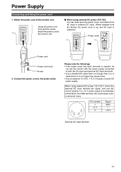
... external 12 V DC, 7 A (10 A peak or more) DC power supply. Connect the power cord to the monitor unit. Please note the followings • If the power cover has been removed or opened, do not use the correct... input terminal 11 Using the power cord hook and the screw, attach the power cord to the monitor unit. ■ When using external DC power (12 V DC), check the external DC input terminal pin signal, and use the... monitor with the power supply connected to both the AC input and external DC input terminals. ...
... external 12 V DC, 7 A (10 A peak or more) DC power supply. Connect the power cord to the monitor unit. Please note the followings • If the power cover has been removed or opened, do not use the correct... input terminal 11 Using the power cord hook and the screw, attach the power cord to the monitor unit. ■ When using external DC power (12 V DC), check the external DC input terminal pin signal, and use the... monitor with the power supply connected to both the AC input and external DC input terminals. ...

User Manual
Page 12
The selected input line (J page 9, ) • VIDEO, SDI1, SDI2, YPBPR/RGB-VIDEO/RGB-COMP. Various indications (FILM mode) • This indicates that the format selected in the "SYSTEM CONFIG" menu to Use the On Screen Menu The screen displays eight types of information: input signal status, picture adjusting knob status, sharpness display, FUNCTION display, audio level meter display, menu display, time code display and closed caption display. Note: "UNSUPPORT SIGNAL" and "NO SIGNAL" may also indicate that "GAMMA SELECT" is pressed. Picture adjusting knob (J page 9, ) • Press or...
The selected input line (J page 9, ) • VIDEO, SDI1, SDI2, YPBPR/RGB-VIDEO/RGB-COMP. Various indications (FILM mode) • This indicates that the format selected in the "SYSTEM CONFIG" menu to Use the On Screen Menu The screen displays eight types of information: input signal status, picture adjusting knob status, sharpness display, FUNCTION display, audio level meter display, menu display, time code display and closed caption display. Note: "UNSUPPORT SIGNAL" and "NO SIGNAL" may also indicate that "GAMMA SELECT" is pressed. Picture adjusting knob (J page 9, ) • Press or...

User Manual
Page 13
Displays instructions on /off from the menu. How to Use the On Screen Menu (continued) FUNCTION display F1:MARKER F2:WFM/VECTOR F3:PIXEL TO PIXEL F4:TIME CODE F5:LEVEL METER XXXXX • Use the menu to the FUNCTION buttons. • This display disappears after 2 minutes of inaction. • You can be switched on/off and set to ON, press any of the "FUNCTION1" to "FUNCTION5" buttons to display the functions assigned to open and set up functions. • When "FUNCTION DISPLAY" (J page 23) is the menu display. • It disappears after 2 seconds of the display (J page 22, "...
Displays instructions on /off from the menu. How to Use the On Screen Menu (continued) FUNCTION display F1:MARKER F2:WFM/VECTOR F3:PIXEL TO PIXEL F4:TIME CODE F5:LEVEL METER XXXXX • Use the menu to the FUNCTION buttons. • This display disappears after 2 minutes of inaction. • You can be switched on/off and set to ON, press any of the "FUNCTION1" to "FUNCTION5" buttons to display the functions assigned to open and set up functions. • When "FUNCTION DISPLAY" (J page 23) is the menu display. • It disappears after 2 seconds of the display (J page 22, "...

User Manual
Page 14
In VITC and LTC display mode: • Displays the time code in the stated order. Note: Read errors are displayed as Closed caption (CC) display • Use the menu to switch display mode (VITC, LTC, VUB, LUB). Note: Read errors are not available during HV DELAY. 14 It also allows you to display closed caption for HD-SDI signal input. How to Use the On Screen Menu (continued) Time code (TC) display • Use the menu to CC4). Note: Closed captions are displayed as ( : ) NDF ( . ) DF In VUB and LUB display modes: • BG8, BG7, BG6, BG5, BG4, BG3, BG2, BG1 ...
In VITC and LTC display mode: • Displays the time code in the stated order. Note: Read errors are displayed as Closed caption (CC) display • Use the menu to switch display mode (VITC, LTC, VUB, LUB). Note: Read errors are not available during HV DELAY. 14 It also allows you to display closed caption for HD-SDI signal input. How to Use the On Screen Menu (continued) Time code (TC) display • Use the menu to CC4). Note: Closed captions are displayed as ( : ) NDF ( . ) DF In VUB and LUB display modes: • BG8, BG7, BG6, BG5, BG4, BG3, BG2, BG1 ...

User Manual
Page 15
Press [ , ] to the previous screen Push [MENU]. 15 To return to select a sub menu and Press [ENTER]. Press [MENU] to green. 2. The settings in the sub menu change to display the MAIN menu. 3. To cancel, press [MENU]. Press [ , ] to Use the On Screen Menu (continued) Menu operations 1. How to select a setting, then press [ENTER]. Press [ , ] to select a menu and press [ENTER]. [MAIN MENU] 4.
Press [ , ] to the previous screen Push [MENU]. 15 To return to select a sub menu and Press [ENTER]. Press [MENU] to green. 2. The settings in the sub menu change to display the MAIN menu. 3. To cancel, press [MENU]. Press [ , ] to Use the On Screen Menu (continued) Menu operations 1. How to select a setting, then press [ENTER]. Press [ , ] to select a menu and press [ENTER]. [MAIN MENU] 4.

User Manual
Page 16
... return settings and adjustments to their factory defaults. Press [ , ] to the previous screen Push [MENU]. 16 5. This saves the user data. *1 Only displayed on the monitor front panel) • Screen adjustments made with the picture adjusting knob Saving user data Loading user data 1. To return to select the "SYSTEM CONFIG" menu...]. Press [ , ] to load and press [ENTER]. User data include the following settings. • Menu settings except "SETUP LOAD/SAVE" (including button function settings on the BT-LH1760.
... return settings and adjustments to their factory defaults. Press [ , ] to the previous screen Push [MENU]. 16 5. This saves the user data. *1 Only displayed on the monitor front panel) • Screen adjustments made with the picture adjusting knob Saving user data Loading user data 1. To return to select the "SYSTEM CONFIG" menu...]. Press [ , ] to load and press [ENTER]. User data include the following settings. • Menu settings except "SETUP LOAD/SAVE" (including button function settings on the BT-LH1760.

User Manual
Page 17
... ENABLE VECTOR MODE VECTOR SCALE TIME CODE *[WHITE BALANCE VAR1-3] GAIN GREEN GAIN BLUE BIAS RED OPERATION LCD MODE SELECT CLOSED CAPTION MODE SELECT BIAS GREEN BIAS BLUE RESET *1 Only displayed on the BT-LH1760. 17 Main Menu Menu configuration MAIN MENU MARKER VIDEO CONFIG SYSTEM CONFIG FUNCTION GPI INPUT SELECT AUDIO...
... ENABLE VECTOR MODE VECTOR SCALE TIME CODE *[WHITE BALANCE VAR1-3] GAIN GREEN GAIN BLUE BIAS RED OPERATION LCD MODE SELECT CLOSED CAPTION MODE SELECT BIAS GREEN BIAS BLUE RESET *1 Only displayed on the BT-LH1760. 17 Main Menu Menu configuration MAIN MENU MARKER VIDEO CONFIG SYSTEM CONFIG FUNCTION GPI INPUT SELECT AUDIO...

User Manual
Page 18
... set, has priority.) *2 These settings are disabled when the GPI function (J page 36) is selected with the camera recorder (Panasonic) Turns the cross hatch grid on GPI PRESET1: Selects the marker displayed by the GPI terminal "MARKER2 ON/OFF" (J page ...monitor or camera recorder marker size. GPI PRESET2: Selects the marker displayed by the GPI terminal "MARKER1 ON/OFF" (J page 36) operation. Normal background 50% background brightness 0% background brightness (black) Displays the center marker. TYPE2: The effective horizontal area meets the EIA-RS170 for NTSC and ITU-R BT...
... set, has priority.) *2 These settings are disabled when the GPI function (J page 36) is selected with the camera recorder (Panasonic) Turns the cross hatch grid on GPI PRESET1: Selects the marker displayed by the GPI terminal "MARKER2 ON/OFF" (J page ...monitor or camera recorder marker size. GPI PRESET2: Selects the marker displayed by the GPI terminal "MARKER1 ON/OFF" (J page 36) operation. Normal background 50% background brightness 0% background brightness (black) Displays the center marker. TYPE2: The effective horizontal area meets the EIA-RS170 for NTSC and ITU-R BT...

User Manual
Page 19
Simultaneous display example The section becomes the "MARKER BACK". VISTA marker CNSCO marker The marker is displayed as a vertical dotted line when "UNDER" is selected under "SCAN" in 16:9 ratio mode.) This marker is displayed as a dotted line. It controls the background of the marker selected with a 16:9 ratio. 16:9 marker: 4:3 marker 95% area marker 4:3 marker: 16:9 marker 80% area marker ■ Center marker Center marker This marker is displayed at the center of the screen. 19 The section becomes the "MARKER BACK". ■ 4:3 marker (Displayed for SD input in 4:3 ...
Simultaneous display example The section becomes the "MARKER BACK". VISTA marker CNSCO marker The marker is displayed as a vertical dotted line when "UNDER" is selected under "SCAN" in 16:9 ratio mode.) This marker is displayed as a dotted line. It controls the background of the marker selected with a 16:9 ratio. 16:9 marker: 4:3 marker 95% area marker 4:3 marker: 16:9 marker 80% area marker ■ Center marker Center marker This marker is displayed at the center of the screen. 19 The section becomes the "MARKER BACK". ■ 4:3 marker (Displayed for SD input in 4:3 ...

User Manual
Page 20
Selects type of the screen during adjustment. The item display moves to the lower part of FILM gamma mode. Color Monochrome * When ON, the CHROMA setting of the picture adjusting knob is displayed. under -scan and normal display. Normal display Under-scan *1 In split-screen display, changes are not reflected to select 0 - 63 and press [ENTER]. *6 To use Other Selects color temperature. under "DVI-D" is selected in the "INPUT SELECT" menu (J page 30). *3 The following sharpness values are not reflected in the main window. *2 These functions are ...
Selects type of the screen during adjustment. The item display moves to the lower part of FILM gamma mode. Color Monochrome * When ON, the CHROMA setting of the picture adjusting knob is displayed. under -scan and normal display. Normal display Under-scan *1 In split-screen display, changes are not reflected to select 0 - 63 and press [ENTER]. *6 To use Other Selects color temperature. under "DVI-D" is selected in the "INPUT SELECT" menu (J page 30). *3 The following sharpness values are not reflected in the main window. *2 These functions are ...