Installation Guide
Page 2
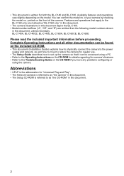
BL-C140A, BL-C140CE, BL-C140E, BL-C160A, BL-C160CE, BL-C160E Please read the included Important Information before proceeding. Complete Operating Instructions and all other documentation can be accessed using a PC. • Refer to the Operating Instructions on the CD-ROM for details regarding the camera's features.... connect the camera to the power supply and network, as well how to mount or place the camera for both the BL-C140 and BL-C160. Abbreviations • UPnP is the abbreviation for "Universal Plug and Play". • The Network Camera is referred to as "the camera" in this...
BL-C140A, BL-C140CE, BL-C140E, BL-C160A, BL-C160CE, BL-C160E Please read the included Important Information before proceeding. Complete Operating Instructions and all other documentation can be accessed using a PC. • Refer to the Operating Instructions on the CD-ROM for details regarding the camera's features.... connect the camera to the power supply and network, as well how to mount or place the camera for both the BL-C140 and BL-C160. Abbreviations • UPnP is the abbreviation for "Universal Plug and Play". • The Network Camera is referred to as "the camera" in this...
Installation Guide
Page 4
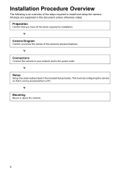
... a PC. Connections Connect the camera to your network and to install and setup the camera. Mounting Mount or place the camera. 4 Installation Procedure Overview The following is an overview of the camera's physical features. This involves configuring the camera so that you know the names of the steps required to the power outlet. Camera Diagram Confirm you have...
... a PC. Connections Connect the camera to your network and to install and setup the camera. Mounting Mount or place the camera. 4 Installation Procedure Overview The following is an overview of the camera's physical features. This involves configuring the camera so that you know the names of the steps required to the power outlet. Camera Diagram Confirm you have...
Installation Guide
Page 6
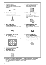
...Right-Angle Joint (1 pc.) (with O-ring) Order No. PQKL10082Z1 Used to attach the camera to secure the camera when wall mounting it. … Power Transfer Unit (1 pc.) Order No. PQHG10765Z Used to power the camera … Flexible Stand (1 pc.) Order No. … Safety Wire (1 pc.) Order... pc.) [BL-C160 Only] Order No. PSHG1235Z Used to protect the camera from water … Foam Strip (1pc.) Order No. PNYCC160A Used to install and configure the camera. - a PC (see the system requirements in the Important Information document) - 2 LAN cables (1 indoor cable and 1 outdoor cable) - ...
...Right-Angle Joint (1 pc.) (with O-ring) Order No. PQKL10082Z1 Used to attach the camera to secure the camera when wall mounting it. … Power Transfer Unit (1 pc.) Order No. PQHG10765Z Used to power the camera … Flexible Stand (1 pc.) Order No. … Safety Wire (1 pc.) Order... pc.) [BL-C160 Only] Order No. PSHG1235Z Used to protect the camera from water … Foam Strip (1pc.) Order No. PNYCC160A Used to install and configure the camera. - a PC (see the system requirements in the Important Information document) - 2 LAN cables (1 indoor cable and 1 outdoor cable) - ...
Installation Guide
Page 7
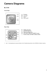
Camera Diagrams BL-C140 Front View A A Housing B B Indicator*1 C Lens D Lens cover C D Rear View E F E Safety wire hole F DATA/POWER IN G G Stand mounting hole H FACTORY DEFAULT RESET button H I Serial number and MAC address label I *1 See 1.1 Understanding the Camera Indicator in the Troubleshooting Guide on the CD-ROM for indicator meaning. 7
Camera Diagrams BL-C140 Front View A A Housing B B Indicator*1 C Lens D Lens cover C D Rear View E F E Safety wire hole F DATA/POWER IN G G Stand mounting hole H FACTORY DEFAULT RESET button H I Serial number and MAC address label I *1 See 1.1 Understanding the Camera Indicator in the Troubleshooting Guide on the CD-ROM for indicator meaning. 7
Installation Guide
Page 8
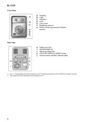
BL-C160 Front View A Housing A B Light C Indicator*1 B D Lens E Lens cover C F Brightness sensor*2 G Built-in sensor (pyroelectric infrared D sensor) E F G Rear View H I H Safety wire hole I DATA/POWER IN J Stand mounting hole K FACTORY DEFAULT RESET button L Serial number and MAC address label J K L *1 See 1.1 Understanding the Camera Indicator in the Troubleshooting Guide on the CD-ROM for indicator meaning. *2 The brightness sensor determines when the light turns on. 8
BL-C160 Front View A Housing A B Light C Indicator*1 B D Lens E Lens cover C F Brightness sensor*2 G Built-in sensor (pyroelectric infrared D sensor) E F G Rear View H I H Safety wire hole I DATA/POWER IN J Stand mounting hole K FACTORY DEFAULT RESET button L Serial number and MAC address label J K L *1 See 1.1 Understanding the Camera Indicator in the Troubleshooting Guide on the CD-ROM for indicator meaning. *2 The brightness sensor determines when the light turns on. 8
Installation Guide
Page 17
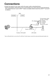
... BL-C140CE/ BL-C140E/ BL-C160CE/ BL-C160E use an AC cord) Power transfer unit Outdoor LAN cable* LAN cable Router * Use a LAN cable that your PC is no more than 30 m (98 feet 5 inches) long to your router and to the power outlet as described below. • Before proceeding, confirm that is connected to connect the camera...
... BL-C140CE/ BL-C140E/ BL-C160CE/ BL-C160E use an AC cord) Power transfer unit Outdoor LAN cable* LAN cable Router * Use a LAN cable that your PC is no more than 30 m (98 feet 5 inches) long to your router and to the power outlet as described below. • Before proceeding, confirm that is connected to connect the camera...
Installation Guide
Page 18
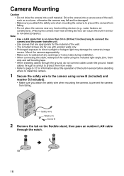
... more than 30 m (98 feet 5 inches) long to connect the camera and the power transfer unit. • Use screws that are appropriate for use with wooden walls only. • Prolonged exposure to direct sunlight or halogen light may fall and be damaged. • Make sure you attach the safety...The included screws are for the material of the wall, such as a column, otherwise the camera may damage the camera's image sensor. Safety wire Washer S Screw B 2 Remove the tab on the flexible stand, then pass an outdoor LAN cable through the ground, do not connect cables under the ground. Mount the...
... more than 30 m (98 feet 5 inches) long to connect the camera and the power transfer unit. • Use screws that are appropriate for use with wooden walls only. • Prolonged exposure to direct sunlight or halogen light may fall and be damaged. • Make sure you attach the safety...The included screws are for the material of the wall, such as a column, otherwise the camera may damage the camera's image sensor. Safety wire Washer S Screw B 2 Remove the tab on the flexible stand, then pass an outdoor LAN cable through the ground, do not connect cables under the ground. Mount the...
Installation Guide
Page 21
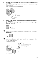
... inch]). To the power outlet (For BL-C140CE/BL-C140E/ BL-C160CE/BL-C160E use an anchor to help secure the camera to the switching hub, router, etc. • The power transfer unit can be fixed in the safety wire, as shown. LAN Cable 10 Connect the outdoor LAN cable connected to the camera to the power transfer unit. 11...
... inch]). To the power outlet (For BL-C140CE/BL-C140E/ BL-C160CE/BL-C160E use an anchor to help secure the camera to the switching hub, router, etc. • The power transfer unit can be fixed in the safety wire, as shown. LAN Cable 10 Connect the outdoor LAN cable connected to the camera to the power transfer unit. 11...
