Installation Guide
Page 1
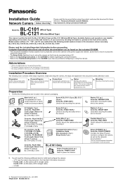
... of your network and to configure the camera, as well as "the CD-ROM" in the included Setup Guide). XTB26+10GFJ Used for wall mounting the camera. PSJA1106Z Cord Length: About 1.8 m (5 feet 11 inches) BL-C101E/BL-C121E BL-C101 Only Power Transfer Unit (1 pc.) Order No. XWG26D12VW Used when securing the safety wire to secure the camera when wall mounting it can confirm the model no . Available features and operations vary slightly...
... of your network and to configure the camera, as well as "the CD-ROM" in the included Setup Guide). XTB26+10GFJ Used for wall mounting the camera. PSJA1106Z Cord Length: About 1.8 m (5 feet 11 inches) BL-C101E/BL-C121E BL-C101 Only Power Transfer Unit (1 pc.) Order No. XWG26D12VW Used when securing the safety wire to secure the camera when wall mounting it can confirm the model no . Available features and operations vary slightly...
Installation Guide
Page 2
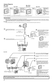
.... Indicator Issues in the included Setup Guide. • If the indicator does not turn green, see 1.2 Camera (For BL- Router WAN LAN 4321 Internet Modem LAN cable (Cat-5 straight cable) PC To the power Green outlet (For BL- D FACTORY DEFAULT RESET button E WIRELESS/WIRED G switch F LAN port H G Serial number label I H Stand/Tripod Mounting Hole J I External I/O interface K J DC IN jack K Hook for indicator meaning. LAN cable Router Modem 3 Connect the AC adaptor to the power transfer unit and plug the...
.... Indicator Issues in the included Setup Guide. • If the indicator does not turn green, see 1.2 Camera (For BL- Router WAN LAN 4321 Internet Modem LAN cable (Cat-5 straight cable) PC To the power Green outlet (For BL- D FACTORY DEFAULT RESET button E WIRELESS/WIRED G switch F LAN port H G Serial number label I H Stand/Tripod Mounting Hole J I External I/O interface K J DC IN jack K Hook for indicator meaning. LAN cable Router Modem 3 Connect the AC adaptor to the power transfer unit and plug the...
Installation Guide
Page 3
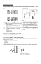
... or reinforced concrete walls. 3 All wiring should be changed (see Section 1.2.7 Detection Notification Sound in the camera's operation bar (for example, turning a light on or off). • This terminal's behavior can be performed by either an open collector circuit. Do not exceed the voltage of a network error or failure. Serious damage to control an external device using the output buttons in the Operating Instructions on the CD...
... or reinforced concrete walls. 3 All wiring should be changed (see Section 1.2.7 Detection Notification Sound in the camera's operation bar (for example, turning a light on or off). • This terminal's behavior can be performed by either an open collector circuit. Do not exceed the voltage of a network error or failure. Serious damage to control an external device using the output buttons in the Operating Instructions on the CD...
Installation Guide
Page 4
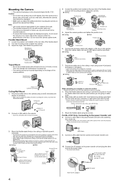
... wire is intended for concrete (in this document depict the BL-C121. Drill for indoor use with wooden walls only. • The camera is firmly mounted on the shape of the ceiling or wall to the floor. For BL-C101 Only: Connecting to attach the camera. 3. Connect a LAN cable to the power transfer unit and to the switching hub, router, etc. • The power transfer unit can be mounted...
... wire is intended for concrete (in this document depict the BL-C121. Drill for indoor use with wooden walls only. • The camera is firmly mounted on the shape of the ceiling or wall to the floor. For BL-C101 Only: Connecting to attach the camera. 3. Connect a LAN cable to the power transfer unit and to the switching hub, router, etc. • The power transfer unit can be mounted...


