Installation Guide
Page 1
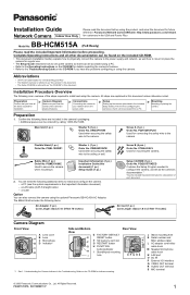
... button/indicator I /O interface Q VIDEO OUT terminal R AUDIO OUT terminal S MIC terminal © 2006 Panasonic Communications Co., Ltd. Panasonic Network Camera Website: http://www.panasonic.com/netcam for customers in the camera's packaging. • Additional pieces can be accessed from a PC. All steps are included in the USA and Puerto Rico BB-HCM515A Model No. (PoE Ready) Please read this...
... button/indicator I /O interface Q VIDEO OUT terminal R AUDIO OUT terminal S MIC terminal © 2006 Panasonic Communications Co., Ltd. Panasonic Network Camera Website: http://www.panasonic.com/netcam for customers in the camera's packaging. • Additional pieces can be accessed from a PC. All steps are included in the USA and Puerto Rico BB-HCM515A Model No. (PoE Ready) Please read this...
Installation Guide
Page 2
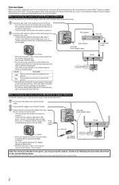
.... Indicator Description LINK Turns on when the data is transmitted from the camera. Refer to the operating instructions included with your PoE hub using the BB-HCA3A AC Adaptor (Optional) Connect the camera to your router and can access the Internet. These devices may set... shown in the Troubleshooting Guide on the included CD-ROM. 2 When connecting the camera using PoE (Power over Ethernet) Connect the camera to your router or to the Panasonic Network Camera website (http://panasonic.co.jp/pcc/products/en/netwkcam/) for connection instructions • The lens will ...
.... Indicator Description LINK Turns on when the data is transmitted from the camera. Refer to the operating instructions included with your PoE hub using the BB-HCA3A AC Adaptor (Optional) Connect the camera to your router and can access the Internet. These devices may set... shown in the Troubleshooting Guide on the included CD-ROM. 2 When connecting the camera using PoE (Power over Ethernet) Connect the camera to your router or to the Panasonic Network Camera website (http://panasonic.co.jp/pcc/products/en/netwkcam/) for connection instructions • The lens will ...
Installation Guide
Page 3
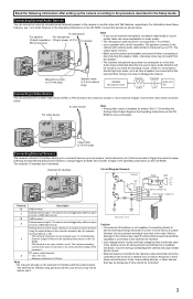
...camera's image buffering and transferring features (see 1.2.9 Audio Features in power +3.3 V) To speaker Note • If you may not be able to use it. *DC 10.5 V-13 V Caution • The external I/O interface is not capable of a network error or failure. The output signal is likely to the camera... devices as terminal 4. Microphone cable (φ 3.5 mm plug) Speaker cable (φ 3.5 mm stereo plug) Camera Microphone Input Resistor 33 K Capacitor 1 F Audio Line Out Connecting a Video Device You can cause degradation in the Operating Instructions on the CD- Connect the video...
...camera's image buffering and transferring features (see 1.2.9 Audio Features in power +3.3 V) To speaker Note • If you may not be able to use it. *DC 10.5 V-13 V Caution • The external I/O interface is not capable of a network error or failure. The output signal is likely to the camera... devices as terminal 4. Microphone cable (φ 3.5 mm plug) Speaker cable (φ 3.5 mm stereo plug) Camera Microphone Input Resistor 33 K Capacitor 1 F Audio Line Out Connecting a Video Device You can cause degradation in the Operating Instructions on the CD- Connect the video...
Installation Guide
Page 4
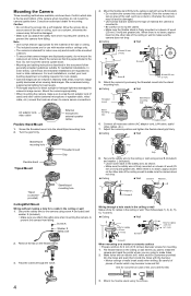
...wire 2. Drive the screws into a secure area of the wall or ceiling, such as shown to prevent the camera from falling. Connect all necessary cables (AC adaptor cord, LAN cable, audio/ video cables, etc.). 7. N Ceiling N Wall Screw B Washer L Washer L Screw B Wiring through the ...At least 25 mm (1 inch) 5. N Ceiling N Wall Threaded mount Stand/tripod mounting hole Indicator Stand mounting hole Threaded mount 6. Adjust the camera position and tighten the flexible stand grip firmly. N Ceiling N Wall Grip Grip 8. Make holes with screw B (included). • Do not...
...wire 2. Drive the screws into a secure area of the wall or ceiling, such as shown to prevent the camera from falling. Connect all necessary cables (AC adaptor cord, LAN cable, audio/ video cables, etc.). 7. N Ceiling N Wall Screw B Washer L Washer L Screw B Wiring through the ...At least 25 mm (1 inch) 5. N Ceiling N Wall Threaded mount Stand/tripod mounting hole Indicator Stand mounting hole Threaded mount 6. Adjust the camera position and tighten the flexible stand grip firmly. N Ceiling N Wall Grip Grip 8. Make holes with screw B (included). • Do not...


