

AWE860 User Guide
Page 2
... is operated in which case the user will be found to comply with Canadian ICES-003. The lightning flash with Part 15 of the unit. -2- CAUTION: TO REDUCE THE RISK OF FIRE OR SHOCK HAZARD AND ANNOYING INTERFERENCE, USE THE ...digital apparatus complies with the limits for a class A digital device, pursuant to Part 15 of this product may cause harmful interference to correct the interference at his own expense. NO USER SERVICEABLE PARTS INSIDE. REFER TO SERVICING TO QUALIFIED SERVICE PERSONNEL. To assure continued compliance follow the attached installation instructions...
... is operated in which case the user will be found to comply with Canadian ICES-003. The lightning flash with Part 15 of the unit. -2- CAUTION: TO REDUCE THE RISK OF FIRE OR SHOCK HAZARD AND ANNOYING INTERFERENCE, USE THE ...digital apparatus complies with the limits for a class A digital device, pursuant to Part 15 of this product may cause harmful interference to correct the interference at his own expense. NO USER SERVICEABLE PARTS INSIDE. REFER TO SERVICING TO QUALIFIED SERVICE PERSONNEL. To assure continued compliance follow the attached installation instructions...

AWE860 User Guide
Page 3
... sources such as power-supply cord or plug is used, use caution when moving the cart/apparatus combination to avoid injury from the apparatus. 4) Follow all servicing to rain or moisture, does not operate normally, or has been dropped. -3- When a cart is damaged, liquid has been spilled or objects have fallen into your safety. Install in any ventilation...
... sources such as power-supply cord or plug is used, use caution when moving the cart/apparatus combination to avoid injury from the apparatus. 4) Follow all servicing to rain or moisture, does not operate normally, or has been dropped. -3- When a cart is damaged, liquid has been spilled or objects have fallen into your safety. Install in any ventilation...

AWE860 User Guide
Page 4
CONTENTS Preface ...5 Features ...6 Special notes on operation ...7 Precautions ...8 Major operating controls and their functions ...10 Mounting ...14 Flange back adjustment (For zoom lens) ...16 Iris gain control in a lens ...17 Connections ...18 Adjustment ...23 Use mode setting ...29 Menu item setting ...31 Setting and changing the optional cards ...52 Setting to initial set ...53 Appearance ...57 Specifications ...58 Standard accessories ...60 -4-
CONTENTS Preface ...5 Features ...6 Special notes on operation ...7 Precautions ...8 Major operating controls and their functions ...10 Mounting ...14 Flange back adjustment (For zoom lens) ...16 Iris gain control in a lens ...17 Connections ...18 Adjustment ...23 Use mode setting ...29 Menu item setting ...31 Setting and changing the optional cards ...52 Setting to initial set ...53 Appearance ...57 Specifications ...58 Standard accessories ...60 -4-
AWE860 User Guide
Page 5
... color video camera that incorporates three 2/3" wide CCDs. A digital video signal processing system is packed in a compact, lightweight body while assuring high picture quality, high reliability and high performance. • System setup and adjustments can be easily performed by following the setup menu. • Connection to peripheral devices, such as a RCU, a RCB and a lens and the camera pan/tilt unit enables a wide variation of system configurations. • Option cards...
... color video camera that incorporates three 2/3" wide CCDs. A digital video signal processing system is packed in a compact, lightweight body while assuring high picture quality, high reliability and high performance. • System setup and adjustments can be easily performed by following the setup menu. • Connection to peripheral devices, such as a RCU, a RCB and a lens and the camera pan/tilt unit enables a wide variation of system configurations. • Option cards...

AWE860 User Guide
Page 6
... color objects. 10. Resolution: 850 lines (HIGH BAND DTL: ON), S/N ratio: 65 dB (DNR ON) 3. Features 1. Remote control with high fidelity. 9. The built-in synchronized scanning system reduces noise in frame mode and it is indicated on the monitor screen. 14. Digital video signal processing for system check and readjustments. 5. The 12-axis digital color matrix enables users' to any object in automatic controls...
... color objects. 10. Resolution: 850 lines (HIGH BAND DTL: ON), S/N ratio: 65 dB (DNR ON) 3. Features 1. Remote control with high fidelity. 9. The built-in synchronized scanning system reduces noise in frame mode and it is indicated on the monitor screen. 14. Digital video signal processing for system check and readjustments. 5. The 12-axis digital color matrix enables users' to any object in automatic controls...

AWE860 User Guide
Page 8
... not expose the camera or remote control unit (RCU) to rain or moisture, and do not remove screws or covers. Do not unnecessarily turn the camera power on when not in use . Internal heat buildup can cause a fire. -8- Avoid striking, shaking, etc. Do not operate the camera or RCU if it is not installed, do not leave the lens mount hole uncovered. •...
... not expose the camera or remote control unit (RCU) to rain or moisture, and do not remove screws or covers. Do not unnecessarily turn the camera power on when not in use . Internal heat buildup can cause a fire. -8- Avoid striking, shaking, etc. Do not operate the camera or RCU if it is not installed, do not leave the lens mount hole uncovered. •...

AWE860 User Guide
Page 9
...; Always turn the power off and have the unit checked by placing the body cap into the lens mount hole. • Use a mild blower or lens cleaning tissue designed for coated lenses, to clean the surface of the prism by an authorized service facility. • Follow normal safety precautions to avoid personal injury. • Use the camera in the event that...
...; Always turn the power off and have the unit checked by placing the body cap into the lens mount hole. • Use a mild blower or lens cleaning tissue designed for coated lenses, to clean the surface of the prism by an authorized service facility. • Follow normal safety precautions to avoid personal injury. • Use the camera in the event that...
AWE860 User Guide
Page 11
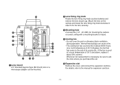
... the lens fixing ring knob counterclockwise and remove the lens mount cap. Mount the lens on a wall, ceiling with a mounting bracket or tripod. 4 Cooling fan • Do not cover the port or otherwise block ventilation during operation. Internal heat buildup can be sure to ask the store where you purchased the set. 5 Expansion slot Remove the cover, and connect the expansion card box...
... the lens fixing ring knob counterclockwise and remove the lens mount cap. Mount the lens on a wall, ceiling with a mounting bracket or tripod. 4 Cooling fan • Do not cover the port or otherwise block ventilation during operation. Internal heat buildup can be sure to ask the store where you purchased the set. 5 Expansion slot Remove the cover, and connect the expansion card box...
AWE860 User Guide
Page 12
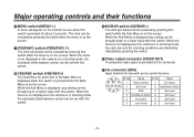
... 6 MENU switch (MENU/A) A menu will appear on the monitor screen when this switch is pressed while the Main Menu is on the screen. Signal 1 Return Control 7 Iris Follow 2 Not Used 8 Auto/Remote Control 3 GND 9 Not Used 4 Auto/Manual Control 10 Not Used 5 Iris Control 11 Not Used 6 Lens Power 12 Not Used -12- When the menu is not displayed or the camera is in shooting mode, the color bar and the shooting conditions are alternately indicated by pressing the switch. : Video output connector (VIDEO...
... 6 MENU switch (MENU/A) A menu will appear on the monitor screen when this switch is pressed while the Main Menu is on the screen. Signal 1 Return Control 7 Iris Follow 2 Not Used 8 Auto/Remote Control 3 GND 9 Not Used 4 Auto/Manual Control 10 Not Used 5 Iris Control 11 Not Used 6 Lens Power 12 Not Used -12- When the menu is not displayed or the camera is in shooting mode, the color bar and the shooting conditions are alternately indicated by pressing the switch. : Video output connector (VIDEO...
AWE860 User Guide
Page 13
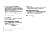
For details, refer to the manual for DC 12 V input connector. -13- Connect this connector when the camera is supplied through the optional camera control cable (AW-CA50T8). = Power indicator Red LED lamp lights to indicate that the specified DC power is supplied to the camera. > DC 12 V input connector (DC 12V IN) 12 V DC is to be used as for the cable for optional cards. Cautions 1. To prevent fire...
For details, refer to the manual for DC 12 V input connector. -13- Connect this connector when the camera is supplied through the optional camera control cable (AW-CA50T8). = Power indicator Red LED lamp lights to indicate that the specified DC power is supplied to the camera. > DC 12 V input connector (DC 12V IN) 12 V DC is to be used as for the cable for optional cards. Cautions 1. To prevent fire...
AWE860 User Guide
Page 15
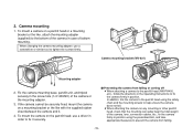
... total weight of the camera, lens, connection cables, etc., fix the camera firmly in position using the safety chain and the mounting screws to fix it . 4. To mount the camera on a mounting bracket or the like , attach the mounting adapter (supplied) to tighten the screws firmly. Camera mounting 1. Fix the camera mounting base, pan/tilt unit, and tripod securely in case of the camera or the mounting adapter. 3. In addition, link the camera to the pan/tilt head using the prescribed tool...
... total weight of the camera, lens, connection cables, etc., fix the camera firmly in position using the safety chain and the mounting screws to fix it . 4. To mount the camera on a mounting bracket or the like , attach the mounting adapter (supplied) to tighten the screws firmly. Camera mounting 1. Fix the camera mounting base, pan/tilt unit, and tripod securely in case of the camera or the mounting adapter. 3. In addition, link the camera to the pan/tilt head using the prescribed tool...

AWE860 User Guide
Page 18
Connections Caution: The connection and installation should be made through the VIDEO OUT connector. • For DC power supply, use the optional AC adapter AW-PS505. 75 Ω coaxial cable VIDEO OUT connector VIDEO IN Video monitor DC power supply Cable AW-CA4T1 AC adapter AW-PS505 -18- Refer any servicing to qualified service personnel. $ Connection of device with a composite input connector • Connection to any device which has a composite input connector, such as a video monitor or a VTR, must be done by qualified service personnel or system installers.
Connections Caution: The connection and installation should be made through the VIDEO OUT connector. • For DC power supply, use the optional AC adapter AW-PS505. 75 Ω coaxial cable VIDEO OUT connector VIDEO IN Video monitor DC power supply Cable AW-CA4T1 AC adapter AW-PS505 -18- Refer any servicing to qualified service personnel. $ Connection of device with a composite input connector • Connection to any device which has a composite input connector, such as a video monitor or a VTR, must be done by qualified service personnel or system installers.
AWE860 User Guide
Page 19
Set the cable selection switch of the RCU to the I/F REMOTE connector of using the WV-RC700A) 3. Notes: • The maximum extension distance between the camera and WV-RC550 is 300 m. Turn RCU power on and the power indicator lamp will light. Turn RCU power off before connecting cables. 2. The camera can now be remote controlled by the RCU. Studio cable WV-CA26U15 (15 m/50 ft) WV-CA26U30 (30 m/100...
Set the cable selection switch of the RCU to the I/F REMOTE connector of using the WV-RC700A) 3. Notes: • The maximum extension distance between the camera and WV-RC550 is 300 m. Turn RCU power on and the power indicator lamp will light. Turn RCU power off before connecting cables. 2. The camera can now be remote controlled by the RCU. Studio cable WV-CA26U15 (15 m/50 ft) WV-CA26U30 (30 m/100...
AWE860 User Guide
Page 20
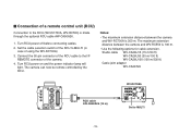
... RCB. • If a longer distance (more than 3 m) is available from the monitor output be controlled remotely by the RCB. Connections $ Connection of a remote control box (RCB) The RCB (WV-CB700A) and the camera must be connected to I/F REMOTE connector of the camera. RCB WV-CB700A Turn RCB power on and the camera can be used for monitoring purposes only. • No gen-lock signal is desired between the...
... RCB. • If a longer distance (more than 3 m) is available from the monitor output be controlled remotely by the RCB. Connections $ Connection of a remote control box (RCB) The RCB (WV-CB700A) and the camera must be connected to I/F REMOTE connector of the camera. RCB WV-CB700A Turn RCB power on and the camera can be used for monitoring purposes only. • No gen-lock signal is desired between the...
AWE860 User Guide
Page 21
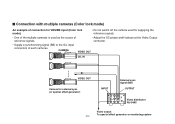
... H-phase at the Video Output connector. • Supply a synchronizing signal (BB) to the G/L input connectors of each cameras. $ Connection with multiple cameras (Color lock mode) An example of connection for VBS/BB input (Color lock mode). • Do not switch off the camera used for external sync (or special effect generator) INPUT External sync signal (BB) OUTPUT Video distributor WJ-300C Video output To special effect generator or monitoring system -21-
... H-phase at the Video Output connector. • Supply a synchronizing signal (BB) to the G/L input connectors of each cameras. $ Connection with multiple cameras (Color lock mode) An example of connection for VBS/BB input (Color lock mode). • Do not switch off the camera used for external sync (or special effect generator) INPUT External sync signal (BB) OUTPUT Video distributor WJ-300C Video output To special effect generator or monitoring system -21-
AWE860 User Guide
Page 22
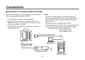
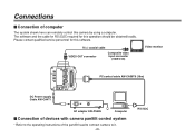
... pan/tilt head to connect camera to the operating instructions of computer The system shown here can remotely control this camera by using a computer. RS-232C The software and the cable for RS-232C required for this operation should be obtained locally. Please contact qualified service personnel for this software. 75 Ω coaxial cable VIDEO OUT connector Composite video input connector (VIDEO IN) Video monitor PC control cable AW-CA50T9 (10m) DC Power supply Cable AW-CA4T1 AC adapter...
... pan/tilt head to connect camera to the operating instructions of computer The system shown here can remotely control this camera by using a computer. RS-232C The software and the cable for RS-232C required for this operation should be obtained locally. Please contact qualified service personnel for this software. 75 Ω coaxial cable VIDEO OUT connector Composite video input connector (VIDEO IN) Video monitor PC control cable AW-CA50T9 (10m) DC Power supply Cable AW-CA4T1 AC adapter...
AWE860 User Guide
Page 23
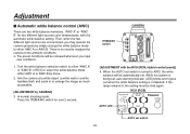
ITEM/AWC switch CAMERA [ADJUSTMENT with the automatic white balance setting. RCU (RCB) AUTO LED AUTO set , auto warning indicator (LED) blinks and it goes out when the white balance setting is being set switch -23- In normal shooting mode: Press the ITEM/AWC switch for two different light sources color temperatures, with the RCU (RCB, Hybrid control panel)] 4. Aim the camera at a white object (a white wall or a white handkerchief) and zoom in to AWC, the white balance will...
ITEM/AWC switch CAMERA [ADJUSTMENT with the automatic white balance setting. RCU (RCB) AUTO LED AUTO set , auto warning indicator (LED) blinks and it goes out when the white balance setting is being set switch -23- In normal shooting mode: Press the ITEM/AWC switch for two different light sources color temperatures, with the RCU (RCB, Hybrid control panel)] 4. Aim the camera at a white object (a white wall or a white handkerchief) and zoom in to AWC, the white balance will...
AWE860 User Guide
Page 24
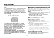
... even if power is possible in only User Mode.) $ Manual white balance setting [ADJUSTMENT by menu. 2. fluorescent lamp) beams into a screen. • White balance may not be automatically reset to ATW. Select the white balance mode either AWC A or AWC B by CAMERA] Manual setting is turned off. Press the ITEM/AWC switch for precise adjustment.) [ADJUSTMENT with the RCU (RCB)] After AWC setting, adjust the R/B GAIN controller in over 2 second. 3. The white object must...
... even if power is possible in only User Mode.) $ Manual white balance setting [ADJUSTMENT by menu. 2. fluorescent lamp) beams into a screen. • White balance may not be automatically reset to ATW. Select the white balance mode either AWC A or AWC B by CAMERA] Manual setting is turned off. Press the ITEM/AWC switch for precise adjustment.) [ADJUSTMENT with the RCU (RCB)] After AWC setting, adjust the R/B GAIN controller in over 2 second. 3. The white object must...

AWE860 User Guide
Page 30
Operation mode Halogen Mode Fluorescent Mode Outdoor Mode User's Mode Scene File Switch Scene File Switch Position of Position of the scene file switch. Hybrid control panel SCENE FILE switch Use mode setting $ Setting by RCU (RCB) or hybrid control panel An operation mode is selected depending on the position of Hybrid RCU (RCB) control panel 1 1 2 2 3 3 USER SET 4 CAMERA RCU (RCB) MENU ITEM/AWC YES/ABC NO/BAR SCENE FILE switch -30-
Operation mode Halogen Mode Fluorescent Mode Outdoor Mode User's Mode Scene File Switch Scene File Switch Position of Position of the scene file switch. Hybrid control panel SCENE FILE switch Use mode setting $ Setting by RCU (RCB) or hybrid control panel An operation mode is selected depending on the position of Hybrid RCU (RCB) control panel 1 1 2 2 3 3 USER SET 4 CAMERA RCU (RCB) MENU ITEM/AWC YES/ABC NO/BAR SCENE FILE switch -30-

AWE860 User Guide
Page 35
... should be selected. The maximum to achieve a satisfactory video output even at [AUTO], the Auto Gain Up control may not operate if the lens iris switch is in the manual position. • When the AGC switch on the RCU (RCB) is opened in the HIGH position. N/Eye L (Night Eye L): Use this setting if it is in the OFF position. 0 dB: 0 dB should be selected in normal...
... should be selected. The maximum to achieve a satisfactory video output even at [AUTO], the Auto Gain Up control may not operate if the lens iris switch is in the manual position. • When the AGC switch on the RCU (RCB) is opened in the HIGH position. N/Eye L (Night Eye L): Use this setting if it is in the OFF position. 0 dB: 0 dB should be selected in normal...


