
Operating Instructions
Page 5
...-5. Saving data on SD memory cards ........95 3-12-5. Input signal settings 96 4-1-1. Setting the DVI input signals 107 4-2-2. Setting the output signals 112 4-3-1. Setting the tally displays 126 4-8-4. DSK adjustments 75 3-6-6. FTB (fade to black 78 3-8. Selecting the AUX output materials ..........80 3-9-2. Effect dissolve 88 3-11. Setting the analog input gain...
...-5. Saving data on SD memory cards ........95 3-12-5. Input signal settings 96 4-1-1. Setting the DVI input signals 107 4-2-2. Setting the output signals 112 4-3-1. Setting the tally displays 126 4-8-4. DSK adjustments 75 3-6-6. FTB (fade to black 78 3-8. Selecting the AUX output materials ..........80 3-9-2. Effect dissolve 88 3-11. Setting the analog input gain...
Operating Instructions
Page 6
... 157 7. Setting the user buttons 135 5-4. External device control 140 5-7-1. TALLY/GPI 156 6-3. Image transmission functions......... 158 8. Selecting the video format 131 5-2. Assigning signals to the crosspoints.......132 5-2-2. Network settings 138 5-6. Enable/Disable Setting for Control ...
... 157 7. Setting the user buttons 135 5-4. External device control 140 5-7-1. TALLY/GPI 156 6-3. Image transmission functions......... 158 8. Selecting the video format 131 5-2. Assigning signals to the crosspoints.......132 5-2-2. Network settings 138 5-6. Enable/Disable Setting for Control ...

Operating Instructions
Page 16
... PC memory card DC IN AC/DC MAINFRAME RJ45 Power AC/DC Control panel Dsub 50 Dsub 9 Dsub 9 TALLY/GPI EDITOR COM ALARM: 1 GPI-OUT: 31 GPI-IN: 8 ALARM: 1 GPI-OUT: 8 GPI-IN: 8 TALLY/GPI Dsub 25 Camera Pan/Tilt Head Controller Editing controller Aux panel 1: When external...
... PC memory card DC IN AC/DC MAINFRAME RJ45 Power AC/DC Control panel Dsub 50 Dsub 9 Dsub 9 TALLY/GPI EDITOR COM ALARM: 1 GPI-OUT: 31 GPI-IN: 8 ALARM: 1 GPI-OUT: 8 GPI-IN: 8 TALLY/GPI Dsub 25 Camera Pan/Tilt Head Controller Editing controller Aux panel 1: When external...

Operating Instructions
Page 17
... 1 2 3 4 5 6 7 8 SDI OUTPUTS 1 2 3 4 DVI-D OUTPUTS 5 9 10 11 12 13 14 15 16 C/C U/C 6 LAN PANEL TALLY/GPI EDITOR REF COM Multi-format Live Switcher AV-HS450N ʙIN1 ʙ IN2 SIGNAL GND Power cord HD SDI HD SDI monitor DVI-D TALLY / GPI SERVICE NORMAL MAINFRAME LCD CONTRAST 12V IN 1 12V IN 2 POWER ON OFF SIGNAL...
... 1 2 3 4 5 6 7 8 SDI OUTPUTS 1 2 3 4 DVI-D OUTPUTS 5 9 10 11 12 13 14 15 16 C/C U/C 6 LAN PANEL TALLY/GPI EDITOR REF COM Multi-format Live Switcher AV-HS450N ʙIN1 ʙ IN2 SIGNAL GND Power cord HD SDI HD SDI monitor DVI-D TALLY / GPI SERVICE NORMAL MAINFRAME LCD CONTRAST 12V IN 1 12V IN 2 POWER ON OFF SIGNAL...

Operating Instructions
Page 18
... not implementing gen-lock (frame synchronizer ON) Example where the optional board is used SLOT A: Analog Input Board (AV-HS04M2) SLOT B: Full-HD DVI Input Board (AV-HS04M8) HD camera DVD player HD Component HD Component HD SDI PC DVI-D PC DVI-D VTR SD SDI HD ...5 6 7 8 SDI OUTPUTS 1 2 3 4 DVI-D OUTPUTS 5 9 10 11 12 13 14 15 16 C/C U/C 6 LAN PANEL TALLY/GPI EDITOR REF COM Multi-format Live Switcher AV-HS450N ʙIN1 ʙ IN2 SIGNAL GND Power cord TALLY / GPI SERVICE NORMAL MAINFRAME LCD CONTRAST 12V IN 1 12V IN 2 POWER ON OFF SIGNAL GND AC adapter...
... not implementing gen-lock (frame synchronizer ON) Example where the optional board is used SLOT A: Analog Input Board (AV-HS04M2) SLOT B: Full-HD DVI Input Board (AV-HS04M8) HD camera DVD player HD Component HD Component HD SDI PC DVI-D PC DVI-D VTR SD SDI HD ...5 6 7 8 SDI OUTPUTS 1 2 3 4 DVI-D OUTPUTS 5 9 10 11 12 13 14 15 16 C/C U/C 6 LAN PANEL TALLY/GPI EDITOR REF COM Multi-format Live Switcher AV-HS450N ʙIN1 ʙ IN2 SIGNAL GND Power cord TALLY / GPI SERVICE NORMAL MAINFRAME LCD CONTRAST 12V IN 1 12V IN 2 POWER ON OFF SIGNAL GND AC adapter...
Operating Instructions
Page 19
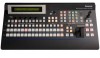
Alarm information can be checked using the unit immediately and be output to an external device from the control panel's TALLY/GPI connector (). For details, refer to contact your dealer. If the alarm goes off, stop using the SYSTEM/Alarm menu. 2. ... message". Control panel User button area Wipe pattern/memory area LCD menu area SD memory card area Positioner area Multi-format Live Switcher AV-HS450 POWER ALARM F1 F2 F3 F4 KEY CKEY KEY AUX PinP1 PinP2 DSK1 DSK2 PinP 1/2 DSK 1/2 AMBER:1 / GREEN :2 TIME CBGD BKGD IMAGE A IMAGE...
Alarm information can be checked using the unit immediately and be output to an external device from the control panel's TALLY/GPI connector (). For details, refer to contact your dealer. If the alarm goes off, stop using the SYSTEM/Alarm menu. 2. ... message". Control panel User button area Wipe pattern/memory area LCD menu area SD memory card area Positioner area Multi-format Live Switcher AV-HS450 POWER ALARM F1 F2 F3 F4 KEY CKEY KEY AUX PinP1 PinP2 DSK1 DSK2 PinP 1/2 DSK 1/2 AMBER:1 / GREEN :2 TIME CBGD BKGD IMAGE A IMAGE...

Operating Instructions
Page 22
...[USER1] to indicate whether MIX or WIPE has been selected when background transitions or key transitions are set to the selected status. KEY ON tally LED This lights in each area 2-1-3. When the [BKGD] button and [KEY] button () are pressed at the same time, both buttons are ... If the [KEY] button () is now pressed, the indicator goes off , and the de-selected status is established. MIX, WIPE selection status tally LEDs These light up to [USER6] buttons on the CONFIG menu. See "5-3-1. Functions in red when the key ON status is established.
...[USER1] to indicate whether MIX or WIPE has been selected when background transitions or key transitions are set to the selected status. KEY ON tally LED This lights in each area 2-1-3. When the [BKGD] button and [KEY] button () are pressed at the same time, both buttons are ... If the [KEY] button () is now pressed, the indicator goes off , and the de-selected status is established. MIX, WIPE selection status tally LEDs These light up to [USER6] buttons on the CONFIG menu. See "5-3-1. Functions in red when the key ON status is established.

Operating Instructions
Page 24
... with the reverse direction (or vice versa) when the transition is completed. (The lighted and extinguished statuses of the [R] button are being executed. Bus tally LEDs These indicate the output statuses of the A bus and B bus. The LED corresponding to manual operation as soon as the fader position overtakes the...
... with the reverse direction (or vice versa) when the transition is completed. (The lighted and extinguished statuses of the [R] button are being executed. Bus tally LEDs These indicate the output statuses of the A bus and B bus. The LED corresponding to manual operation as soon as the fader position overtakes the...

Operating Instructions
Page 29
... input sockets [12V IN1], [12V IN2] (DC 12 V, 0.8 A) Connect the supplied AC adapters (for maintenance purposes. Rear panel connections area TALLY / GPI SERVICE NORMAL MAINFRAME LCD CONTRAST 12V IN 1 12V IN 2 POWER ON OFF SIGNAL GND &#...61527; TALLY/GPI input/output connector [TALLY/GPI] (D-sub 25-pin, female, inch screw) For details on and off. SERVICE switch [NORMAL/SERVICE] This ...
... input sockets [12V IN1], [12V IN2] (DC 12 V, 0.8 A) Connect the supplied AC adapters (for maintenance purposes. Rear panel connections area TALLY / GPI SERVICE NORMAL MAINFRAME LCD CONTRAST 12V IN 1 12V IN 2 POWER ON OFF SIGNAL GND &#...61527; TALLY/GPI input/output connector [TALLY/GPI] (D-sub 25-pin, female, inch screw) For details on and off. SERVICE switch [NORMAL/SERVICE] This ...
Operating Instructions
Page 30
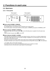
... redundant power supply system. The alarm information can be checked using the unit immediately and be output to an external device from the TALLY/GPI connector () of the mainframe. For details, refer to turn off , stop using the SYSTEM/Alarm menu. ...Power supply 2 POWER1 OFF ON POWER1 ALARM1 POWER2 OFF ON POWER2 ALARM2 Multi-format Live Switcher AV-HS450 Power switch [POWER1, POWER2] These are used to "5-8-2. 2. As a standard feature, this occurs, an alarm message is displayed on the ...
... redundant power supply system. The alarm information can be checked using the unit immediately and be output to an external device from the TALLY/GPI connector () of the mainframe. For details, refer to turn off , stop using the SYSTEM/Alarm menu. ...Power supply 2 POWER1 OFF ON POWER1 ALARM1 POWER2 OFF ON POWER2 ALARM2 Multi-format Live Switcher AV-HS450 Power switch [POWER1, POWER2] These are used to "5-8-2. 2. As a standard feature, this occurs, an alarm message is displayed on the ...

Operating Instructions
Page 31
... SLOT B IN/OUT B1 IN/OUT B2 ʙIN1 SDI INPUTS 1 2 3 4 5 6 7 8 SDI OUTPUTS 1 2 3 4 DVI-D OUTPUTS 5 9 10 11 12 13 14 15 16 C/C U/C 6 LAN PANEL TALLY/GPI EDITOR REF COM ʙ IN2 SIGNAL GND SDI signal input connectors [SDI INPUTS 1 to 16] 9 to 16: The color...
... SLOT B IN/OUT B1 IN/OUT B2 ʙIN1 SDI INPUTS 1 2 3 4 5 6 7 8 SDI OUTPUTS 1 2 3 4 DVI-D OUTPUTS 5 9 10 11 12 13 14 15 16 C/C U/C 6 LAN PANEL TALLY/GPI EDITOR REF COM ʙ IN2 SIGNAL GND SDI signal input connectors [SDI INPUTS 1 to 16] 9 to 16: The color...

Operating Instructions
Page 32
External interfaces". TALLY/GPI input/output connector [TALLY/GPI] (D-sub 50-pin, female, inch screw) For details on how to connect this socket and the other end to "6. Be absolutely sure to ...
External interfaces". TALLY/GPI input/output connector [TALLY/GPI] (D-sub 50-pin, female, inch screw) For details on how to connect this socket and the other end to "6. Be absolutely sure to ...

Operating Instructions
Page 37
... [TIME] button to 999f can be set when seconds are pressed at an interim setting, the transition is executed instantly. 37 Basic operations 3-1-4. The bus tally LEDs on the video format. 59.94i: max. 33s09f, 59.94p: max. 16s39f, 50i: max. 39s24f, 50p: max. 19s49f, 24psf: max 41s15f, 23.98psf: max...
... [TIME] button to 999f can be set when seconds are pressed at an interim setting, the transition is executed instantly. 37 Basic operations 3-1-4. The bus tally LEDs on the video format. 59.94i: max. 33s09f, 59.94p: max. 16s39f, 50i: max. 39s24f, 50p: max. 19s49f, 24psf: max 41s15f, 23.98psf: max...

Operating Instructions
Page 99
...↓| | 2/13 | Frame| Off| Field On Turn [F3] to freeze the input image or cancel the freeze. Frame: The images are frozen, the tally signals of Freeze. Frame or Field can be automatically switched to "On". With interlace signals, however, diagonal lines and moving images. LCD menu area". ...
...↓| | 2/13 | Frame| Off| Field On Turn [F3] to freeze the input image or cancel the freeze. Frame: The images are frozen, the tally signals of Freeze. Frame or Field can be automatically switched to "On". With interlace signals, however, diagonal lines and moving images. LCD menu area". ...

Operating Instructions
Page 125
... input, the "c" mark is displayed in front of the name of the split frame (gray scale). MV 2|Frame | Char|Label |Tally MV1Frame| LUM75%| LUM75%| On|Red+GRN MV 4|Frame | Char|Label |Tally MV2Frame| LUM75%| LUM75%| On|Red+GRN LUM 0% LUM 0% Off Red LUM25% LUM25% Off LUM50% LUM50% LUM100% LUM100% Off Off LUM...
... input, the "c" mark is displayed in front of the name of the split frame (gray scale). MV 2|Frame | Char|Label |Tally MV1Frame| LUM75%| LUM75%| On|Red+GRN MV 4|Frame | Char|Label |Tally MV2Frame| LUM75%| LUM75%| On|Red+GRN LUM 0% LUM 0% Off Red LUM25% LUM25% Off LUM50% LUM50% LUM100% LUM100% Off Off LUM...

Operating Instructions
Page 126
... 0% LUM 0% Off Red LUM25% LUM25% Off LUM50% LUM50% LUM100% LUM100% Off Off Red+GRN: Both the red tally and green tally are output from the tally output connector on the rear panel. Refer to be superimposed onto the split frame of program outputs. Setting the GPI... been completely faded out to set the tally displays using the Tally item. At this time, the green tally is displayed. Setting the tally displays Set the tally displays to "5-7-3. The green tally indicates material selected by the preset bus. 4. The red tally indicates material consisting of the multi view...
... 0% LUM 0% Off Red LUM25% LUM25% Off LUM50% LUM50% LUM100% LUM100% Off Off Red+GRN: Both the red tally and green tally are output from the tally output connector on the rear panel. Refer to be superimposed onto the split frame of program outputs. Setting the GPI... been completely faded out to set the tally displays using the Tally item. At this time, the green tally is displayed. Setting the tally displays Set the tally displays to "5-7-3. The green tally indicates material selected by the preset bus. 4. The red tally indicates material consisting of the multi view...

Operating Instructions
Page 142
... of mainframe: GPIM-In sub menu and GPIM-Out sub menu CONFIG 4|Port |Assign | GPIM-In | -|NoAsign| |GPIEN |Disable Port1~8 Enable TALLY/GPI connector of the user buttons. See "5-3-1. 5. Setting the GPI The user can set the functions that are to be controlled from the ... and set enable or disable for the GPIEN item can be assigned using the Assign item. Refer to "Control using the GPIEN item. TALLY/GPI" and "6-3-1. TALLY/GPI". Press the [CONFIG] button to light its indicator and display the CONFIG menu. Refer to be exercised from each...
... of mainframe: GPIM-In sub menu and GPIM-Out sub menu CONFIG 4|Port |Assign | GPIM-In | -|NoAsign| |GPIEN |Disable Port1~8 Enable TALLY/GPI connector of the user buttons. See "5-3-1. 5. Setting the GPI The user can set the functions that are to be controlled from the ... and set enable or disable for the GPIEN item can be assigned using the Assign item. Refer to "Control using the GPIEN item. TALLY/GPI" and "6-3-1. TALLY/GPI". Press the [CONFIG] button to light its indicator and display the CONFIG menu. Refer to be exercised from each...

Operating Instructions
Page 143
.... 143 Output Low pulses are performed using contact inputs (or disabled in progress for FTB R-Tly1 to 20 Red tally for INPUT1 to 20 G-Tly1 to 20 Green tally for INPUT1 to 20 NoAsign No function assigned Control method Operations are output (approx. 50 to 60 ms). Functions are ... background is selected KEYAUTO AUTO button when the key is selected KEYCUT CUT button when the key is selected RTlyDBL Red tally signal is not output GTlyDBL Green tally signal is not output NoAsign No function assigned Output from the GPI output port Assign Item Description of function ...
.... 143 Output Low pulses are performed using contact inputs (or disabled in progress for FTB R-Tly1 to 20 Red tally for INPUT1 to 20 G-Tly1 to 20 Green tally for INPUT1 to 20 NoAsign No function assigned Control method Operations are output (approx. 50 to 60 ms). Functions are ... background is selected KEYAUTO AUTO button when the key is selected KEYCUT CUT button when the key is selected RTlyDBL Red tally signal is not output GTlyDBL Green tally signal is not output NoAsign No function assigned Output from the GPI output port Assign Item Description of function ...

Operating Instructions
Page 144
... the camera and pan-tilt head can be controlled. 5. Functions that the power of the equipment is connected directly to a pan-tilt head, the red tally signal and power on/off before proceeding to five cameras can be controlled from the COM connector. 144 System settings 5-7-4. Up to connect the cables...
... the camera and pan-tilt head can be controlled. 5. Functions that the power of the equipment is connected directly to a pan-tilt head, the red tally signal and power on/off before proceeding to five cameras can be controlled from the COM connector. 144 System settings 5-7-4. Up to connect the cables...

Operating Instructions
Page 145
... IN/OUT B1 IN/OUT B2 SDI INPUTS 1 2 3 4 5 6 7 8 SDI OUTPUTS 1 2 3 4 DVI-D OUTPUTS 5 9 10 6 11 12 13 LAN PANEL 14 15 16 C/C U/C TALLY/GPI AV-HS450N EDITOR REF COM COM connector ʙIN1 ʙ IN2 SIGNAL GND AW-RP655N RS-422RS-232C converter Cable length: Max. 656... ft. (200 m) Twisted pair cable (AWG24) AV-HS450N Pin No. 1 2 3 4 5 6 7 8 9 Signal FRAME GND RXD - TXD + GND NC GND RXD + TXD - CTS For pin assignments and specifi...
... IN/OUT B1 IN/OUT B2 SDI INPUTS 1 2 3 4 5 6 7 8 SDI OUTPUTS 1 2 3 4 DVI-D OUTPUTS 5 9 10 6 11 12 13 LAN PANEL 14 15 16 C/C U/C TALLY/GPI AV-HS450N EDITOR REF COM COM connector ʙIN1 ʙ IN2 SIGNAL GND AW-RP655N RS-422RS-232C converter Cable length: Max. 656... ft. (200 m) Twisted pair cable (AWG24) AV-HS450N Pin No. 1 2 3 4 5 6 7 8 9 Signal FRAME GND RXD - TXD + GND NC GND RXD + TXD - CTS For pin assignments and specifi...