
AKHC931 User Guide
Page 1
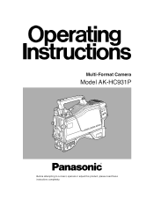
Multi-Format Camera Model AK-HC931P Before attempting to connect, operate or adjust this product, please read these instructions completely.
Multi-Format Camera Model AK-HC931P Before attempting to connect, operate or adjust this product, please read these instructions completely.
AKHC931 User Guide
Page 3
Contents For your safety 2 Overview 4 Features 4 Controls and their functions 5 Mounting the lens 10 Adjusting the lens flange back 11 Performing the viewfinder adjustments 12 Connecting the microphone 14 Mounting the camera on a tripod 15 Component system configuration 16 System connections 1 (with Multi-Format Camera 18 System connections 2 (with build-up unit 19 System connections 3 (with MSU 20 Status displays on viewfinder screen 21 Menu operations 22 Setting menu configuration 24 AK-HC931P Connector pin assignment 27 External dimension drawing 28 Specifications 29 3
Contents For your safety 2 Overview 4 Features 4 Controls and their functions 5 Mounting the lens 10 Adjusting the lens flange back 11 Performing the viewfinder adjustments 12 Connecting the microphone 14 Mounting the camera on a tripod 15 Component system configuration 16 System connections 1 (with Multi-Format Camera 18 System connections 2 (with build-up unit 19 System connections 3 (with MSU 20 Status displays on viewfinder screen 21 Menu operations 22 Setting menu configuration 24 AK-HC931P Connector pin assignment 27 External dimension drawing 28 Specifications 29 3
AKHC931 User Guide
Page 4
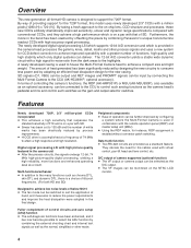
...result. D/C output of operation can be further improved by connecting the Multi-Format Camera to achieve a compact size and light weight. SD signals (D1, VBS) can be input by configuring a system where the Multi-Format Camera is a choice of 8 boost frequencies. (For both HD and SD) Designed...with a high signal-to-noise ratio from the dark areas to support the 720P format. A newly developed casing is accomplished at hand, and measures to select the ASU function by combining Panasonic's unique horizontal line readout CCDs with high picture quality featured in combination with ...
...result. D/C output of operation can be further improved by connecting the Multi-Format Camera to achieve a compact size and light weight. SD signals (D1, VBS) can be input by configuring a system where the Multi-Format Camera is a choice of 8 boost frequencies. (For both HD and SD) Designed...with a high signal-to-noise ratio from the dark areas to support the 720P format. A newly developed casing is accomplished at hand, and measures to select the ASU function by combining Panasonic's unique horizontal line readout CCDs with high picture quality featured in combination with ...
AKHC931 User Guide
Page 6
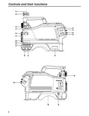
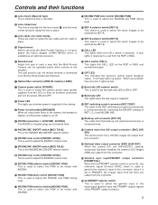
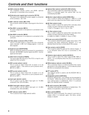
Controls and their functions V _ PTT RET W X Y Z ^ ] \ [ NAM R G Y /C B FILTER LOCAL MONI SEL 1A ND FILTER CC 1 CAP 3200K A 2 CLEAR 4300K B 3 1 / 4ND 6300K C 4 1/16ND CROSS D 5 1/64ND DF0 E CAM/VTR GAIN ON ON LOW OUTPUT CAM W.BAL B MID BAR A STBY SAVE HIGH TEST PRST PTT USER SEL _` PHANT OFF PHANT OFF AB AB -40 -30 -20 -40 -30 -50 -60 -20 -50 -60 (dB) (dB) MIC1 MIC2 R S U T a F OPT FIBER HD SDI OUT AUX OUT PROMPTER/GL 6 VF E 1 ULTI FORMAT DIGITAL CAMERA SYSTEM MONITOR OUT LENS MIC1 j i
Controls and their functions V _ PTT RET W X Y Z ^ ] \ [ NAM R G Y /C B FILTER LOCAL MONI SEL 1A ND FILTER CC 1 CAP 3200K A 2 CLEAR 4300K B 3 1 / 4ND 6300K C 4 1/16ND CROSS D 5 1/64ND DF0 E CAM/VTR GAIN ON ON LOW OUTPUT CAM W.BAL B MID BAR A STBY SAVE HIGH TEST PRST PTT USER SEL _` PHANT OFF PHANT OFF AB AB -40 -30 -20 -40 -30 -50 -60 -20 -50 -60 (dB) (dB) MIC1 MIC2 R S U T a F OPT FIBER HD SDI OUT AUX OUT PROMPTER/GL 6 VF E 1 ULTI FORMAT DIGITAL CAMERA SYSTEM MONITOR OUT LENS MIC1 j i
AKHC931 User Guide
Page 7
... has occurred, it is mounted. D RET switching control connector [RET CONT] The cable of the RET switching box (optional accessory) is used to select the camera power input (power supplied from the CCU or from an external connector) and turn the power ON and OFF. 2 Power LED This lights up green... selector switch This is input to this lever is used to clamp the lens cable and mic cable in such a way that the Multi-Format Camera can be switched by LEMO) @ CALL switch [CALL] This lights the CALL LED on the shoulder. D Tripod mount Before securing the Multi-Format...
... has occurred, it is mounted. D RET switching control connector [RET CONT] The cable of the RET switching box (optional accessory) is used to select the camera power input (power supplied from the CCU or from an external connector) and turn the power ON and OFF. 2 Power LED This lights up green... selector switch This is input to this lever is used to clamp the lens cable and mic cable in such a way that the Multi-Format Camera can be switched by LEMO) @ CALL switch [CALL] This lights the CALL LED on the shoulder. D Tripod mount Before securing the Multi-Format...
AKHC931 User Guide
Page 8
...can also supplied. A: 3200K, B: 4300K, C: 6300K, D: Cross, E: DFO [ Power save switch [CAM/VTR] This is used to select the gain for the camera images. For details on its operation, refer to this connector. when it is connected to this connector. P Earphone jack [EARPHONE] When an earphone (optional accessory... [MONI SEL] This is used to select the video output (CAM, BAR or TEST). It is not effective when the CCU is connected to the camera. ] Camera output selector switch [OUTPUT] This is used to select the images (Y, NAM, R, G, B] which are to be supplied to MIC2. (The switch ...
...can also supplied. A: 3200K, B: 4300K, C: 6300K, D: Cross, E: DFO [ Power save switch [CAM/VTR] This is used to select the gain for the camera images. For details on its operation, refer to this connector. when it is connected to this connector. P Earphone jack [EARPHONE] When an earphone (optional accessory... [MONI SEL] This is used to select the video output (CAM, BAR or TEST). It is not effective when the CCU is connected to the camera. ] Camera output selector switch [OUTPUT] This is used to select the images (Y, NAM, R, G, B] which are to be supplied to MIC2. (The switch ...

AKHC931 User Guide
Page 9
...output selector switch. It is not effective when the CCU is connected to this connector. g Lens connector [LENS] The lens cable is connected to the camera. e AWB/ABB start switch of the lens. What kind power is to be used. k Rear VF connector This D-sub connector is used as ... on the menu. For details on the menu operations, refer to be supplied is set to ON when the electronic shutter is connected to the camera. f VTR start/RET selector switch [VTR/RET] This is used for the monitor are output from this dial button. h Front MIC1 connector [MIC1] A microphone...
...output selector switch. It is not effective when the CCU is connected to this connector. g Lens connector [LENS] The lens cable is connected to the camera. e AWB/ABB start switch of the lens. What kind power is to be used. k Rear VF connector This D-sub connector is used as ... on the menu. For details on the menu operations, refer to be supplied is set to ON when the electronic shutter is connected to the camera. f VTR start/RET selector switch [VTR/RET] This is used for the monitor are output from this dial button. h Front MIC1 connector [MIC1] A microphone...

AKHC931 User Guide
Page 10
... center mark on the lens mounted, it to the LENS connector. Auto iris operation speed adjustment for the lens (performed using the controls on the camera) 3 Lower the lens clamp lever to clamp the lens in place. 10 Flange back adjustment for the lens 2. Mounting the lens 1 Raise the ... lever, and remove the mount cap. 4 Insert the cable into the cable clamp and connect it may be necessary to perform the following lens and camera adjustments. 1. Center mark ≥ For details on handling the lens, refer to the instructions that accompany the lens. ≥ Depending on the lens ...
... center mark on the lens mounted, it to the LENS connector. Auto iris operation speed adjustment for the lens (performed using the controls on the camera) 3 Lower the lens clamp lever to clamp the lens in place. 10 Flange back adjustment for the lens 2. Mounting the lens 1 Raise the ... lever, and remove the mount cap. 4 Insert the cable into the cable clamp and connect it may be necessary to perform the following lens and camera adjustments. 1. Center mark ≥ For details on handling the lens, refer to the instructions that accompany the lens. ≥ Depending on the lens ...
AKHC931 User Guide
Page 11
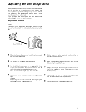
... the zoom ring to the wide-angle position, and turn the F.f ring to the instructions that accompany the lens. Adjustment method For details on the camera. If the video level is obtained at both the telephoto and wide-angle settings when zoom operations are to manual, and open the iris. 3 Set...
... the zoom ring to the wide-angle position, and turn the F.f ring to the instructions that accompany the lens. Adjustment method For details on the camera. If the video level is obtained at both the telephoto and wide-angle settings when zoom operations are to manual, and open the iris. 3 Set...

AKHC931 User Guide
Page 12
... the viewfinder along and off the plate. When connecting the plug to the viewfinder's connector. Pull up the knob Detaching the viewfinder 1 Check that the camera's POWER switch is at the OFF position. 2 Attach the accessory mounting plate to the viewfinder. 5 Connect the plug to the viewfinder's connector, ensure that the...
... the viewfinder along and off the plate. When connecting the plug to the viewfinder's connector. Pull up the knob Detaching the viewfinder 1 Check that the camera's POWER switch is at the OFF position. 2 Attach the accessory mounting plate to the viewfinder. 5 Connect the plug to the viewfinder's connector, ensure that the...
AKHC931 User Guide
Page 14
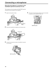
... cable to the MIC IN connector on the viewfinder. 1 Open the microphone holder. 4 If the audio channel whose signals are to be mounted on the camera.
... cable to the MIC IN connector on the viewfinder. 1 Open the microphone holder. 4 If the audio channel whose signals are to be mounted on the camera.

AKHC931 User Guide
Page 15
... move the black lever in the direction of the camera and tripod together when selecting the holes for attaching the camera. Bear in the direction of the screws on the tripod. Tripod attachment Tripod platform Detaching the camera from the tripod attachment While pushing the red lever,...diameter of the selected holes match the diameter of the arrow to return the pin to mount the camera on a tripod. 1 Mount the tripod attachment on the tripod platform. Mounting the camera on a tripod Use the tripod attachment, available as an optional accessory, to its original position....
... move the black lever in the direction of the camera and tripod together when selecting the holes for attaching the camera. Bear in the direction of the screws on the tripod. Tripod attachment Tripod platform Detaching the camera from the tripod attachment While pushing the red lever,...diameter of the selected holes match the diameter of the arrow to return the pin to mount the camera on a tripod. 1 Mount the tripod attachment on the tripod platform. Mounting the camera on a tripod Use the tripod attachment, available as an optional accessory, to its original position....
AKHC931 User Guide
Page 16
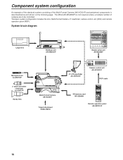
... BLK KNEE CLIP GAMMA UNDO PED FLAME GAMMA GAIN HD. The basic system configuration includes the lens, Multi-Format Camera, 2z viewfinder, camera control unit (CCU) and remote operation panel (ROP). DTL HD.FACE SD. DTL MATRIX SYSTEM FUNC SD memory card RP-SD008B FILTER ND HEAD CAP 100 25 6.3... page. DTL OFF HD. Component system configuration An example of the standard system consisting of the Multi-Format Camera (AK-HC931P) and peripheral components is not required unless a multiple number of cameras are to be controlled. DTL SD. System block diagram Large lens Build-up ...
... BLK KNEE CLIP GAMMA UNDO PED FLAME GAMMA GAIN HD. The basic system configuration includes the lens, Multi-Format Camera, 2z viewfinder, camera control unit (CCU) and remote operation panel (ROP). DTL HD.FACE SD. DTL MATRIX SYSTEM FUNC SD memory card RP-SD008B FILTER ND HEAD CAP 100 25 6.3... page. DTL OFF HD. Component system configuration An example of the standard system consisting of the Multi-Format Camera (AK-HC931P) and peripheral components is not required unless a multiple number of cameras are to be controlled. DTL SD. System block diagram Large lens Build-up ...
AKHC931 User Guide
Page 17
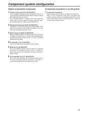
...-HCU931P) This is the Multi-Format Camera's camera control unit. It is connected to mount a larger lens (optional accessory) on the camera's power switch. 17 It can operate up . Then turn on the Multi-Format Camera. Component system configuration Outline of cameras and CCUs are used, the MSU ...can be operated when the system is built up to the ON position. Component...
...-HCU931P) This is the Multi-Format Camera's camera control unit. It is connected to mount a larger lens (optional accessory) on the camera's power switch. 17 It can operate up . Then turn on the Multi-Format Camera. Component system configuration Outline of cameras and CCUs are used, the MSU ...can be operated when the system is built up to the ON position. Component...

AKHC931 User Guide
Page 18
... after the CCU main power switch has been set to ON, the camera can be controlled using the ROP. 5 Upon completion of shooting, set the CCU camera power switch and main power switch to OFF. 18 DTL SD. DTL MATRIX SYSTEM FUNC FILTER ND HEAD CAP 100 25 6.3 1.6 1 SCENE FILE 2 3 4 5 STORE R 1 2 3 4 5 R GAIN G B CC...
... after the CCU main power switch has been set to ON, the camera can be controlled using the ROP. 5 Upon completion of shooting, set the CCU camera power switch and main power switch to OFF. 18 DTL SD. DTL MATRIX SYSTEM FUNC FILTER ND HEAD CAP 100 25 6.3 1.6 1 SCENE FILE 2 3 4 5 STORE R 1 2 3 4 5 R GAIN G B CC...
AKHC931 User Guide
Page 19
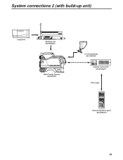
...CAM/VTR GAIN ON ON LOW OUTPUT CAM W.BAL B MID BAR A STBY SAVE HIGH TEST PRST PTT USER SEL Multi-Format Camera AK-HC931P 8z LCD viewfinder AK-HVF931P CABLE OPEN SHORT ALARM FUSE 125V 5A FUSE 250V 2.5A TALLY/CALL MAIN HEAD POWER ...LEVEL COXN PGN1 PGN OFF PGN2 PUSH PRIVATE MIC ON OFF PTT Camera control unit AK-HCU931P ROP cable ROP ON HEAD ON VFPW CAMERA NO. DTL SD. DTL MATRIX SYSTEM FUNC FILTER ND HEAD CAP 100 25 6.3 1.6 1 SCENE FILE 2 3 4 5 STORE R 1 2 3 4 5 R GAIN G B CC 1.1 4.3 6.3 8.0 MONITOR G B SEQ ...
...CAM/VTR GAIN ON ON LOW OUTPUT CAM W.BAL B MID BAR A STBY SAVE HIGH TEST PRST PTT USER SEL Multi-Format Camera AK-HC931P 8z LCD viewfinder AK-HVF931P CABLE OPEN SHORT ALARM FUSE 125V 5A FUSE 250V 2.5A TALLY/CALL MAIN HEAD POWER ...LEVEL COXN PGN1 PGN OFF PGN2 PUSH PRIVATE MIC ON OFF PTT Camera control unit AK-HCU931P ROP cable ROP ON HEAD ON VFPW CAMERA NO. DTL SD. DTL MATRIX SYSTEM FUNC FILTER ND HEAD CAP 100 25 6.3 1.6 1 SCENE FILE 2 3 4 5 STORE R 1 2 3 4 5 R GAIN G B CC 1.1 4.3 6.3 8.0 MONITOR G B SEQ ...
AKHC931 User Guide
Page 20
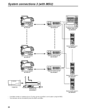
... HD. MATRIX SD. FACE ON ON CHARACTER ON SHADING UNDO BLACK WHITE R B CONTROL BLK G GAMMA SLOW MATRIX SHATTER FUNC SYSTEM PED GAIN GAMMA FLARE W. ROP ON HEAD ON VFPW CAMERA NO. DTL MATRIX SYSTEM FUNC FILTER ND HEAD CAP 100 25 6.3 1.6 1 SCENE FILE 2 3 4 5 STORE R 1 2 3 4 5 R GAIN G B CC 1.1 4.3 6.3...IRIS RANGE Remote Operation Panel AK-HRP930P Remote operation panel 14 AK-HRP931P ROP ON HEAD ON VFPW CAMERA NO. MATRIX CLIP OFF OFF OFF HD. DTL SD. System connections 3 (with MSU) NAM Y /C RG B FILTER LOCAL MONI SEL 1A ND FILTER CC ...
... HD. MATRIX SD. FACE ON ON CHARACTER ON SHADING UNDO BLACK WHITE R B CONTROL BLK G GAMMA SLOW MATRIX SHATTER FUNC SYSTEM PED GAIN GAMMA FLARE W. ROP ON HEAD ON VFPW CAMERA NO. DTL MATRIX SYSTEM FUNC FILTER ND HEAD CAP 100 25 6.3 1.6 1 SCENE FILE 2 3 4 5 STORE R 1 2 3 4 5 R GAIN G B CC 1.1 4.3 6.3...IRIS RANGE Remote Operation Panel AK-HRP930P Remote operation panel 14 AK-HRP931P ROP ON HEAD ON VFPW CAMERA NO. MATRIX CLIP OFF OFF OFF HD. DTL SD. System connections 3 (with MSU) NAM Y /C RG B FILTER LOCAL MONI SEL 1A ND FILTER CC ...
AKHC931 User Guide
Page 21
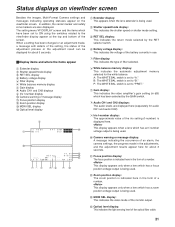
...4 Battery voltage display 5 Filter display 6 White balance memory display 7 Gain display 8 Audio CH1 and CH2 displays 9 Iris f-number display : Camera warning or message display ; This display appears only when a lens which has an f-number voltage output is indicated here in use. 5 Filter display... statuses appear on the viewfinder screen. Focus position display: The focus position is being used . : Camera warning or message display: A message indicating the occurrence of an alarm, the camera settings, the progress made , a message with details of the setting, the status of a number....
...4 Battery voltage display 5 Filter display 6 White balance memory display 7 Gain display 8 Audio CH1 and CH2 displays 9 Iris f-number display : Camera warning or message display ; This display appears only when a lens which has an f-number voltage output is indicated here in use. 5 Filter display... statuses appear on the viewfinder screen. Focus position display: The focus position is being used . : Camera warning or message display: A message indicating the occurrence of an alarm, the camera settings, the progress made , a message with details of the setting, the status of a number....

AKHC931 User Guide
Page 22
... Mark Sel 1 Line Width 4 4 When the JOG dial is pressed, the data is pressed, the setting of the item indicated by the arrow flashes. The camera's USER menu screen now appears on the viewfinder or monitor. VF Setting1 Side Modulation 15 Zone Mark 13:9 Safety Mark 16:9 Center Mark OFF Center...
... Mark Sel 1 Line Width 4 4 When the JOG dial is pressed, the data is pressed, the setting of the item indicated by the arrow flashes. The camera's USER menu screen now appears on the viewfinder or monitor. VF Setting1 Side Modulation 15 Zone Mark 13:9 Safety Mark 16:9 Center Mark OFF Center...

AKHC931 User Guide
Page 24
... Viewfinder settings1 VF Setting2 Viewfinder settings2 VF Display1 Viewfinder display settings VF Display2 Viewfinder display settings Setting1 Camera settings1 Setting2 Camera settings2 Setting3 Camera settings3 INCOM INCOM settings !LED Camera status display settings 24 7"VF Side Modulation (for changing the brightness level of the signals outside the... the gain SW to MID gain) GAIN SW HIGH (for setting the gain SW to HIGH gain) ID NUMBER (for setting the camera number and designation) CH1 ENG/PD (for switching INCOM1) CH2 ENG/PD (for switching INCOM2) CH1 CCU/CRANE (for switching crane...
... Viewfinder settings1 VF Setting2 Viewfinder settings2 VF Display1 Viewfinder display settings VF Display2 Viewfinder display settings Setting1 Camera settings1 Setting2 Camera settings2 Setting3 Camera settings3 INCOM INCOM settings !LED Camera status display settings 24 7"VF Side Modulation (for changing the brightness level of the signals outside the... the gain SW to MID gain) GAIN SW HIGH (for setting the gain SW to HIGH gain) ID NUMBER (for setting the camera number and designation) CH1 ENG/PD (for switching INCOM1) CH2 ENG/PD (for switching INCOM2) CH1 CCU/CRANE (for switching crane...


