
AKHC931 User Guide
Page 1
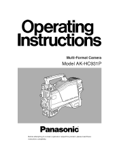
Multi-Format Camera Model AK-HC931P Before attempting to connect, operate or adjust this product, please read these instructions completely.
Multi-Format Camera Model AK-HC931P Before attempting to connect, operate or adjust this product, please read these instructions completely.

AKHC931 User Guide
Page 2
... appliance. Operation of this product. Don't look into directly into the Optical fiber connector of this product is a laser class 1 product complies with the instruction manual, may be required to qualified personnel. Don't make any modifications. NO USER SERVICEABLE PARTS INSIDE. FCC Note: This device complies with Canadian ICES-003. Don't repair by yourself. For CANADA This class A digital apparatus...
... appliance. Operation of this product. Don't look into directly into the Optical fiber connector of this product is a laser class 1 product complies with the instruction manual, may be required to qualified personnel. Don't make any modifications. NO USER SERVICEABLE PARTS INSIDE. FCC Note: This device complies with Canadian ICES-003. Don't repair by yourself. For CANADA This class A digital apparatus...
AKHC931 User Guide
Page 3
Contents For your safety 2 Overview 4 Features 4 Controls and their functions 5 Mounting the lens 10 Adjusting the lens flange back 11 Performing the viewfinder adjustments 12 Connecting the microphone 14 Mounting the camera on a tripod 15 Component system configuration 16 System connections 1 (with Multi-Format Camera 18 System connections 2 (with build-up unit 19 System connections 3 (with MSU 20 Status displays on viewfinder screen 21 Menu operations 22 Setting menu configuration 24 AK-HC931P Connector pin assignment 27 External dimension drawing 28 Specifications 29 3
Contents For your safety 2 Overview 4 Features 4 Controls and their functions 5 Mounting the lens 10 Adjusting the lens flange back 11 Performing the viewfinder adjustments 12 Connecting the microphone 14 Mounting the camera on a tripod 15 Component system configuration 16 System connections 1 (with Multi-Format Camera 18 System connections 2 (with build-up unit 19 System connections 3 (with MSU 20 Status displays on viewfinder screen 21 Menu operations 22 Setting menu configuration 24 AK-HC931P Connector pin assignment 27 External dimension drawing 28 Specifications 29 3
AKHC931 User Guide
Page 4
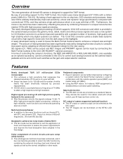
... number of white marks has been drastically reduced by configuring a system where the Multi-Format Camera is used in the final design. Fuller complement of 74 MHz to attain a high response and high resolution. D/C output of camera supported (optional function) ≥ The VF output or camera output can be switched to suit the application at a frequency of control circuits and auto setup (ASU) function ≥ The self-diagnosis functions...
... number of white marks has been drastically reduced by configuring a system where the Multi-Format Camera is used in the final design. Fuller complement of 74 MHz to attain a high response and high resolution. D/C output of camera supported (optional function) ≥ The VF output or camera output can be switched to suit the application at a frequency of control circuits and auto setup (ASU) function ≥ The self-diagnosis functions...
AKHC931 User Guide
Page 7
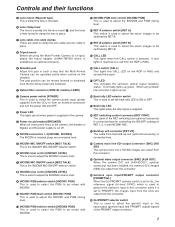
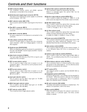
... with INCOM2. D RET switching control connector [RET CONT] The cable of the RET switching box (optional accessory) is pressed. F Camera main line SDI output connector (BNC) [HD SDI] The camera main line's HD-SDI images are connected here. when it lights up red. 1 Camera power switch [POWER] This is used to PROMPT, the images input from the CCU are output from the build-up red when power is used to this connector...
... with INCOM2. D RET switching control connector [RET CONT] The cable of the RET switching box (optional accessory) is pressed. F Camera main line SDI output connector (BNC) [HD SDI] The camera main line's HD-SDI images are connected here. when it lights up red. 1 Camera power switch [POWER] This is used to PROMPT, the images input from the CCU are output from the build-up red when power is used to this connector...
AKHC931 User Guide
Page 8
...] The trunk data [RS-422 x2] of the white balance. when it is pressed again, the menu screen display is inserted here. Y ND filter selector knob This is used to adjust the optical filter manually when LOCAL has been selected as return image selector switch. It is not effective when the CCU is connected to the camera. ^ White balance selector switch [W.BAL] This is used to this...
...] The trunk data [RS-422 x2] of the white balance. when it is pressed again, the menu screen display is inserted here. Y ND filter selector knob This is used to adjust the optical filter manually when LOCAL has been selected as return image selector switch. It is not effective when the CCU is connected to the camera. ^ White balance selector switch [W.BAL] This is used to this...

AKHC931 User Guide
Page 9
... cable is connected to this connector. The power supply for the microphone can be output are established by operating this dial button. The images to the camera. It performs the same operations as the REC start /RET selector switch [VTR/RET] This is set to ON when the electronic shutter is connected to be allocated as desired on the menu operations. g Lens connector [LENS] The lens cable is used as the VTR button...
... cable is connected to this connector. The power supply for the microphone can be output are established by operating this dial button. The images to the camera. It performs the same operations as the REC start /RET selector switch [VTR/RET] This is set to ON when the electronic shutter is connected to be allocated as desired on the menu operations. g Lens connector [LENS] The lens cable is used as the VTR button...

AKHC931 User Guide
Page 10
... remove the mount cap. 4 Insert the cable into the cable clamp and connect it may be necessary to the LENS connector. Auto iris operation speed adjustment for the lens 2. Center mark ≥ For details on handling the lens, refer to the instructions that accompany the lens. ≥ Depending on the lens mounted, it to perform the following lens and camera adjustments. 1. White shading adjustment for the lens (performed using the controls on...
... remove the mount cap. 4 Insert the cable into the cable clamp and connect it may be necessary to the LENS connector. Auto iris operation speed adjustment for the lens 2. Center mark ≥ For details on handling the lens, refer to the instructions that accompany the lens. ≥ Depending on the lens mounted, it to perform the following lens and camera adjustments. 1. White shading adjustment for the lens (performed using the controls on...
AKHC931 User Guide
Page 11
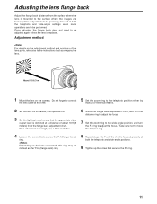
... manual or electrical means. 2 Set the lens iris to manual, and open the iris. 3 Set the lighting in such a way that the appropriate video output level is replaced. If the video level is focused properly at both the telephoto and wide-angle settings when zoom operations are formed) if the subject fails to be adjusted again unless the lens is obtained at a distance of the lens parts, refer also to the instructions...
... manual or electrical means. 2 Set the lens iris to manual, and open the iris. 3 Set the lighting in such a way that the appropriate video output level is replaced. If the video level is focused properly at both the telephoto and wide-angle settings when zoom operations are formed) if the subject fails to be adjusted again unless the lens is obtained at a distance of the lens parts, refer also to the instructions...
AKHC931 User Guide
Page 14
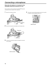
... IN AUDIO IN switch Clamp screw 3 Connect the microphone cable to F. Connecting a microphone When the microphone is mounted on the viewfinder (optional accessory) for use The microphone of the microphone kit AJ-MC700P (optional accessory) can be mounted on the viewfinder. 1 Open the microphone holder. 4 If the audio channel whose signals are to be recorded so requires, set the AUDIO IN switch to the MIC IN connector on the camera.
... IN AUDIO IN switch Clamp screw 3 Connect the microphone cable to F. Connecting a microphone When the microphone is mounted on the viewfinder (optional accessory) for use The microphone of the microphone kit AJ-MC700P (optional accessory) can be mounted on the viewfinder. 1 Open the microphone holder. 4 If the audio channel whose signals are to be recorded so requires, set the AUDIO IN switch to the MIC IN connector on the camera.
AKHC931 User Guide
Page 16
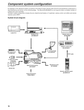
... IRIS RANGE Remote Operation Panel AK-HRP930P Remote operation panel AK-HRP931P 16 FACE SD. DTL OFF HD. System block diagram Large lens Build-up unit AK-HBU931P CABLE TALLY CAMERA 1 2 3 4 5 6 5600K FLARE BLK GAMMA OFF GAMMA ON OFF MODE KNEE OFF WHITE HD. MATRIX SD. FACE SD CARD CARD RESET HEAD POWER ALL ALARM REF FILE LOCAL ALL REF STORE STORE CLOSE BAR TEST WHITE AUTO BLACK SET UP...
... IRIS RANGE Remote Operation Panel AK-HRP930P Remote operation panel AK-HRP931P 16 FACE SD. DTL OFF HD. System block diagram Large lens Build-up unit AK-HBU931P CABLE TALLY CAMERA 1 2 3 4 5 6 5600K FLARE BLK GAMMA OFF GAMMA ON OFF MODE KNEE OFF WHITE HD. MATRIX SD. FACE SD CARD CARD RESET HEAD POWER ALL ALARM REF FILE LOCAL ALL REF STORE STORE CLOSE BAR TEST WHITE AUTO BLACK SET UP...
AKHC931 User Guide
Page 17
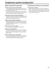
... Multi-Format Camera. Component connections in an SD system 1 Component connections Refer to pages 18 to the Multi-Format Camera using the ROP cable (optional accessory), and enables the camera, CCU and lens to be operated by remote control. 3 Master setup unit (MSU:AK-MSU930P) When a multiple number of cameras and CCUs are used to mount a larger lens (optional accessory) on the camera's power switch. 17 Then turn on the Multi-Format Camera. Component system configuration...
... Multi-Format Camera. Component connections in an SD system 1 Component connections Refer to pages 18 to the Multi-Format Camera using the ROP cable (optional accessory), and enables the camera, CCU and lens to be operated by remote control. 3 Master setup unit (MSU:AK-MSU930P) When a multiple number of cameras and CCUs are used to mount a larger lens (optional accessory) on the camera's power switch. 17 Then turn on the Multi-Format Camera. Component system configuration...

AKHC931 User Guide
Page 18
...) MIC1 MIC2 CAM/VTR GAIN ON ON LOW OUTPUT CAM W.BAL B MID BAR A STBY SAVE HIGH TEST PRST PTT USER SEL Multi-Format Camera AK-HC931P CABLE OPEN SHORT ALARM FUSE 125V 5A FUSE 250V 2.5A TALLY/CALL MAIN HEAD POWER LEVEL COXN PGN1 PGN OFF PGN2 PUSH PRIVATE MIC ON OFF PTT Camera control unit AK-HCU931P ROP cable ROP ON HEAD ON VFPW CAMERA NO. DTL...
...) MIC1 MIC2 CAM/VTR GAIN ON ON LOW OUTPUT CAM W.BAL B MID BAR A STBY SAVE HIGH TEST PRST PTT USER SEL Multi-Format Camera AK-HC931P CABLE OPEN SHORT ALARM FUSE 125V 5A FUSE 250V 2.5A TALLY/CALL MAIN HEAD POWER LEVEL COXN PGN1 PGN OFF PGN2 PUSH PRIVATE MIC ON OFF PTT Camera control unit AK-HCU931P ROP cable ROP ON HEAD ON VFPW CAMERA NO. DTL...
AKHC931 User Guide
Page 19
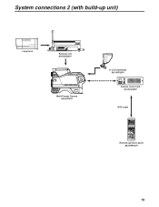
... CAM/VTR GAIN ON ON LOW OUTPUT CAM W.BAL B MID BAR A STBY SAVE HIGH TEST PRST PTT USER SEL Multi-Format Camera AK-HC931P 8z LCD viewfinder AK-HVF931P CABLE OPEN SHORT ALARM FUSE 125V 5A FUSE 250V 2.5A TALLY/CALL MAIN HEAD POWER LEVEL COXN PGN1 PGN OFF PGN2 PUSH PRIVATE MIC ON OFF PTT Camera control unit AK-HCU931P ROP cable ROP ON HEAD ON VFPW CAMERA...
... CAM/VTR GAIN ON ON LOW OUTPUT CAM W.BAL B MID BAR A STBY SAVE HIGH TEST PRST PTT USER SEL Multi-Format Camera AK-HC931P 8z LCD viewfinder AK-HVF931P CABLE OPEN SHORT ALARM FUSE 125V 5A FUSE 250V 2.5A TALLY/CALL MAIN HEAD POWER LEVEL COXN PGN1 PGN OFF PGN2 PUSH PRIVATE MIC ON OFF PTT Camera control unit AK-HCU931P ROP cable ROP ON HEAD ON VFPW CAMERA...
AKHC931 User Guide
Page 20
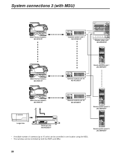
... ON LOW OUTPUT CAM W.BAL B MID BAR A STBY SAVE HIGH TEST PRST PTT USER SEL Multi-Format Camera AK-HC931P CABLE OPEN SHORT ALARM FUSE 125V 5A FUSE 250V 2.5A TALLY/CALL MAIN HEAD POWER LEVEL COXN PGN1 PGN OFF PGN2 PUSH PRIVATE MIC ON OFF PTT Camera control unit 15 AK-HCU931P Large lens Build-up unit AK-HBU931P • A multiple number of cameras (up to...
... ON LOW OUTPUT CAM W.BAL B MID BAR A STBY SAVE HIGH TEST PRST PTT USER SEL Multi-Format Camera AK-HC931P CABLE OPEN SHORT ALARM FUSE 125V 5A FUSE 250V 2.5A TALLY/CALL MAIN HEAD POWER LEVEL COXN PGN1 PGN OFF PGN2 PUSH PRIVATE MIC ON OFF PTT Camera control unit 15 AK-HCU931P Large lens Build-up unit AK-HBU931P • A multiple number of cameras (up to...
AKHC931 User Guide
Page 21
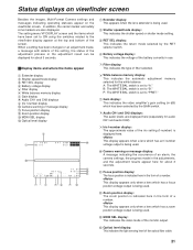
... display: This indicates the type of filter selected. 6 White balance memory display: This indicates the automatic adjustment selected for the white balance. The setting menu VF DISPLAY screen and the items which has an f-number voltage output is being used . 2 Shutter speed/mode display: This indicates the shutter speed or shutter mode setting. 3 RET SEL display: This indicates the return mode selected by the GAIN switch. 8 Audio CH1 and CH2 displays: The audio levels are also displayed. memory 7 Gain display: This indicates the video amplifier's gain setting...
... display: This indicates the type of filter selected. 6 White balance memory display: This indicates the automatic adjustment selected for the white balance. The setting menu VF DISPLAY screen and the items which has an f-number voltage output is being used . 2 Shutter speed/mode display: This indicates the shutter speed or shutter mode setting. 3 RET SEL display: This indicates the return mode selected by the GAIN switch. 8 Audio CH1 and CH2 displays: The audio levels are also displayed. memory 7 Gain display: This indicates the video amplifier's gain setting...

AKHC931 User Guide
Page 22
... Width 4 3 Turn the JOG dial to OFF while the setting is pressed, the setting of the item indicated by the arrow flashes. The camera's USER menu screen now appears on...menu data After accessing the item menus, enter the respective data. 1 Turn the JOG dial to select the menu item to be set to change the setting. VF Setting1 Side Modulation 15 Zone Mark 4:3 Safety Mark 16:9 Center Mark OFF Center Mark Sel 1 Line Width 4 4 When the JOG dial is pressed, the data is entered. Menu operations Basic setting menu operations _ Displaying the menus User menu 1 Press the MENU button...
... Width 4 3 Turn the JOG dial to OFF while the setting is pressed, the setting of the item indicated by the arrow flashes. The camera's USER menu screen now appears on...menu data After accessing the item menus, enter the respective data. 1 Turn the JOG dial to select the menu item to be set to change the setting. VF Setting1 Side Modulation 15 Zone Mark 4:3 Safety Mark 16:9 Center Mark OFF Center Mark Sel 1 Line Width 4 4 When the JOG dial is pressed, the data is entered. Menu operations Basic setting menu operations _ Displaying the menus User menu 1 Press the MENU button...

AKHC931 User Guide
Page 24
... voltage display to ON or OFF) COLOR TEMP (for setting the color temperature display to ON or OFF) White Ch (for setting the white balance memory) FAN POWER (for setting the camera fan to ON or OFF) FAN MODE (for setting the camera fan mode) USER SW (for setting the user switch) OUTPUT SEL (for setting the analog output to Y/Pb/Pr or RGB) H PHASE (for setting the horizontal phase) CABLE COMP (for setting the analog output cable compensation...
... voltage display to ON or OFF) COLOR TEMP (for setting the color temperature display to ON or OFF) White Ch (for setting the white balance memory) FAN POWER (for setting the camera fan to ON or OFF) FAN MODE (for setting the camera fan mode) USER SW (for setting the user switch) OUTPUT SEL (for setting the analog output to Y/Pb/Pr or RGB) H PHASE (for setting the horizontal phase) CABLE COMP (for setting the analog output cable compensation...

AKHC931 User Guide
Page 26
... Date/Time Camera s internal calendar function settings SD CARD SD card operations with the camera MODE (for selecting the format, load or storage mode) FILE No (for setting the file number to be used) EXECUTE (for executing card operations) FORM CONV Camera s built-in downconverter settings MODE (for setting the down-converter mode) Iris Cont Auto Iris Window Select Iris Level Pear/Ratio A.Iris Range (for setting the range of adjusting fine auto iris level with iris volume joystick) A.Iris Speed (for setting the auto iris speed...
... Date/Time Camera s internal calendar function settings SD CARD SD card operations with the camera MODE (for selecting the format, load or storage mode) FILE No (for setting the file number to be used) EXECUTE (for executing card operations) FORM CONV Camera s built-in downconverter settings MODE (for setting the down-converter mode) Iris Cont Auto Iris Window Select Iris Level Pear/Ratio A.Iris Range (for setting the range of adjusting fine auto iris level with iris volume joystick) A.Iris Speed (for setting the auto iris speed...

AKHC931 User Guide
Page 29
... has been installed) Control 1) Power selection: EXT, OFF, CCU 2) USER SEL: Functions specified by menu items can be allocated to the switch. 3) RET A/B selection: For selecting the return signal 4) Front tally selection: Front tally HIGH, LOW, OFF (VF unit) 5) Viewfinder marker selection: Center marker, safety zone, 4:3 marker 6) Gain selection: LOW, MID, HIGH 7) Output selection: CAM, BAR, TEST 8) White balance mode: A, B, preset 9) Shutter speed selection...
... has been installed) Control 1) Power selection: EXT, OFF, CCU 2) USER SEL: Functions specified by menu items can be allocated to the switch. 3) RET A/B selection: For selecting the return signal 4) Front tally selection: Front tally HIGH, LOW, OFF (VF unit) 5) Viewfinder marker selection: Center marker, safety zone, 4:3 marker 6) Gain selection: LOW, MID, HIGH 7) Output selection: CAM, BAR, TEST 8) White balance mode: A, B, preset 9) Shutter speed selection...


