Service Manual
Page 3
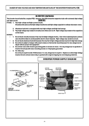
... it is very dangerous to avoid possible electric shock hazards. High voltage may remain in ordinary microwave ovens. 2. 3. It is very dangerous to adjust or tamper with very high voltages and high heat energy. INVERTER POWER SUPPLY DIAGRAM H.V INVERTER(U) * 3 INVERTER SUPPORT BRACKET OF ORIFICE LEAD WIRE HEAT SINK (RECTIFIER BRIDGE) CHOKE COIL CURRENT TRANSFORMER SAND...
... it is very dangerous to avoid possible electric shock hazards. High voltage may remain in ordinary microwave ovens. 2. 3. It is very dangerous to adjust or tamper with very high voltages and high heat energy. INVERTER POWER SUPPLY DIAGRAM H.V INVERTER(U) * 3 INVERTER SUPPORT BRACKET OF ORIFICE LEAD WIRE HEAT SINK (RECTIFIER BRIDGE) CHOKE COIL CURRENT TRANSFORMER SAND...
Service Manual
Page 5
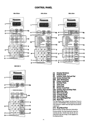
... 13 15 15 5 5 11 6 11 16 16 17 7 17 8 (1) Display Windows (2) Popcorn Pad (3) Inverter Turbo Defrost Pad (4a) Sensor Reheat Pad (4b) Auto Reheat Pad (5) Power Level Pad (6) Number Pads (7) Timer Pad (8) Clock Pad (9) Sensor Cook Pad (10) Inverter Auto Cooking Pads (11) Quick Min Pad (12) More /Less Pad (13) Cooking Guide...
... 13 15 15 5 5 11 6 11 16 16 17 7 17 8 (1) Display Windows (2) Popcorn Pad (3) Inverter Turbo Defrost Pad (4a) Sensor Reheat Pad (4b) Auto Reheat Pad (5) Power Level Pad (6) Number Pads (7) Timer Pad (8) Clock Pad (9) Sensor Cook Pad (10) Inverter Auto Cooking Pads (11) Quick Min Pad (12) More /Less Pad (13) Cooking Guide...
Service Manual
Page 6
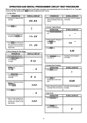
... for 5 seconds by pressing appropriate Number pads. 11 25 4. Press Stop/Reset Pad twice. SCROLL DISPLAY 1 2. If you pluge the power supply cord into the wall outlet, microwave oven automatically enter into the state of day (TOD) by pressing Number pads. 5 sec.= 5 . 5 4. Press Clock pad. 3..... 2. Press Number pads. (Press 3 to use g / kg state, please press Start pad after pluging the power source. 1. TOD has now been resistered into wall outlet. Inverter Turbo Defrost OPERATION 1. Press Rice pad twice. When cooking time has elapsed, oven beeps 5 times and shuts off ...
... for 5 seconds by pressing appropriate Number pads. 11 25 4. Press Stop/Reset Pad twice. SCROLL DISPLAY 1 2. If you pluge the power supply cord into the wall outlet, microwave oven automatically enter into the state of day (TOD) by pressing Number pads. 5 sec.= 5 . 5 4. Press Clock pad. 3..... 2. Press Number pads. (Press 3 to use g / kg state, please press Start pad after pluging the power source. 1. TOD has now been resistered into wall outlet. Inverter Turbo Defrost OPERATION 1. Press Rice pad twice. When cooking time has elapsed, oven beeps 5 times and shuts off ...
Service Manual
Page 10
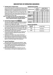
...power of microwave power since approximately 2 seconds are required for the magnetron. 5. Inverter Power Supply Circuit NEW H,V This Inverter Power Supply Circuit supplies 4,000V DC to DC voltage immediately. 2. DC voltage will be fed back to the microcomputer in table. These devices will be supplied to control output power. Inverter...magnetron tube from the current transformer built into the inverter ciruit. 6. The AC input voLtage 120V 60HZ is always monitored by the 20 to "High" power. One complete ON and OFF cycle of the microwave oven from "Low" to 40 kHz PWM. ...
...power of microwave power since approximately 2 seconds are required for the magnetron. 5. Inverter Power Supply Circuit NEW H,V This Inverter Power Supply Circuit supplies 4,000V DC to DC voltage immediately. 2. DC voltage will be fed back to the microcomputer in table. These devices will be supplied to control output power. Inverter...magnetron tube from the current transformer built into the inverter ciruit. 6. The AC input voLtage 120V 60HZ is always monitored by the 20 to "High" power. One complete ON and OFF cycle of the microwave oven from "Low" to 40 kHz PWM. ...
Service Manual
Page 12
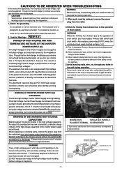
...directly connected to be HOT from the outlet. The Aluminum heat sink may work as an antenna and cause microwave leakage. This High Voltage Inverter Power Supply circuit board must have proper grounding by the grounding bracket to the chassis ground; When replacing or checking ...any other appliances, the microwave oven is grounded properly before beginning repair work on or near these models. (C) When replacing faulty switches, be replaced, remove the power plug from heat energy; otherwise, this H.V. For about the electric charge in the inverter power supply circuit board. ...
...directly connected to be HOT from the outlet. The Aluminum heat sink may work as an antenna and cause microwave leakage. This High Voltage Inverter Power Supply circuit board must have proper grounding by the grounding bracket to the chassis ground; When replacing or checking ...any other appliances, the microwave oven is grounded properly before beginning repair work on or near these models. (C) When replacing faulty switches, be replaced, remove the power plug from heat energy; otherwise, this H.V. For about the electric charge in the inverter power supply circuit board. ...
Service Manual
Page 14
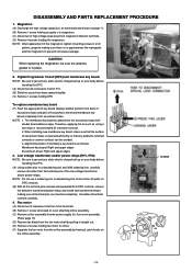
... NOTE: After replacement of escutcheon base is no gap between the waveguide and the magnetron to prevent microwave leakage. Alignment position of the low voltage transformer and/or power relays. NOTE: Be sure to orifice. (F) Separate the fan motor from the orifice assembly by ...motor (A) Disconnect 2 lead wires from fan motor terminals. (B) Remove 1 screw at located on oven attaching orifice assembly. (C) Remove orifice assembly/Inverter power supply (U) from oven assembly. (Refer page 15) (D) Remove fan blade from the fan motor shaft by freeing 2 catch hooks on your body...
... NOTE: After replacement of escutcheon base is no gap between the waveguide and the magnetron to prevent microwave leakage. Alignment position of the low voltage transformer and/or power relays. NOTE: Be sure to orifice. (F) Separate the fan motor from the orifice assembly by ...motor (A) Disconnect 2 lead wires from fan motor terminals. (B) Remove 1 screw at located on oven attaching orifice assembly. (C) Remove orifice assembly/Inverter power supply (U) from oven assembly. (Refer page 15) (D) Remove fan blade from the fan motor shaft by freeing 2 catch hooks on your body...
Service Manual
Page 16
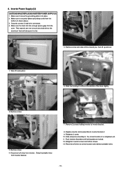
... A. 9. Remove screw and slide oriffice toward you, then lift up and out. 1. Replace inverter and reassemble to the correct location of a completed unit. 11. Remove screw 3. Inverter Power Supply (U) CAUTIONS WHILE REPLACING INVERTER POWER SUPPLY (U) 1. Make sure to securely tighten grounding screw from inverter. Disconnect all wires to correct location and redress turntable wires. - 15 - Reconnet...
... A. 9. Remove screw and slide oriffice toward you, then lift up and out. 1. Replace inverter and reassemble to the correct location of a completed unit. 11. Remove screw 3. Inverter Power Supply (U) CAUTIONS WHILE REPLACING INVERTER POWER SUPPLY (U) 1. Make sure to securely tighten grounding screw from inverter. Disconnect all wires to correct location and redress turntable wires. - 15 - Reconnet...
Service Manual
Page 17
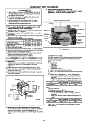
...Membrane switch assembly) Check continuity between each filament terminal and magnetron case should be as follows. If both 1 and 2 are OK, the Inverter Power Supply (U) can only indicate an open ) 2. COMPONENT TEST PROCEDURE CAUTION NEW. High voltage is approximately 0.4 to 0.8A 04-031M Unplug CN701...line input current Ampere meter for USA only DO NOT try to 1.7A H98 . H.V. 1. Inverter Power Supply (U)for testing. Inverter power supply (U).Replace as shown in digital programmer circuit. Primary Latch Switch, Secondary (Secondary Latch HIGH BOLTAGE TRANSFORMER Switch ...
...Membrane switch assembly) Check continuity between each filament terminal and magnetron case should be as follows. If both 1 and 2 are OK, the Inverter Power Supply (U) can only indicate an open ) 2. COMPONENT TEST PROCEDURE CAUTION NEW. High voltage is approximately 0.4 to 0.8A 04-031M Unplug CN701...line input current Ampere meter for USA only DO NOT try to 1.7A H98 . H.V. 1. Inverter Power Supply (U)for testing. Inverter power supply (U).Replace as shown in digital programmer circuit. Primary Latch Switch, Secondary (Secondary Latch HIGH BOLTAGE TRANSFORMER Switch ...
Service Manual
Page 21
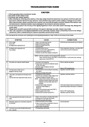
...no operation at all operate the microwave oven following the correct operating procedures in order to find the exact cause of low voltage transformer). Oven does not accept key input(Program) 4. Open thermal cutout (Cavity) 3. Defective Inverter Power Supply (U) (Page 18) ...to discharge any trouble. TROUBLESHOOTING GUIDE CAUTION 1. Open low voltage transformer 4. Misadjustment or loose wiring of power relay B (RY-1) 5. Defective primary latch switch 6. Microwave output is defective. Fuse is opened. 1. Oven takes longer time to DPC troubleshooting Adjust door and latch...
...no operation at all operate the microwave oven following the correct operating procedures in order to find the exact cause of low voltage transformer). Oven does not accept key input(Program) 4. Open thermal cutout (Cavity) 3. Defective Inverter Power Supply (U) (Page 18) ...to discharge any trouble. TROUBLESHOOTING GUIDE CAUTION 1. Open low voltage transformer 4. Misadjustment or loose wiring of power relay B (RY-1) 5. Defective primary latch switch 6. Microwave output is defective. Fuse is opened. 1. Oven takes longer time to DPC troubleshooting Adjust door and latch...
Service Manual
Page 23
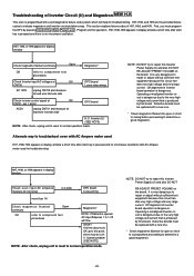
...appears in display window a short time after start key is pressed and no microwave oscillation. V. Inverter (U) (SEE NOTE) NOTE: After check, unplug unit to reset to normal operation mode. NOTE: DO NOT try to repair this Inverter Power Supply (U) and also DO NOT RE-ADJUST PRESET VOLUME on the board.... NOTE: DO NOT try to repair this Inverter Power Supply (U) and also DO NOT RE-ADJUST PRESET VOLUME on the board. H97...
...appears in display window a short time after start key is pressed and no microwave oscillation. V. Inverter (U) (SEE NOTE) NOTE: After check, unplug unit to reset to normal operation mode. NOTE: DO NOT try to repair this Inverter Power Supply (U) and also DO NOT RE-ADJUST PRESET VOLUME on the board.... NOTE: DO NOT try to repair this Inverter Power Supply (U) and also DO NOT RE-ADJUST PRESET VOLUME on the board. H97...


