Service Manual
Page 3
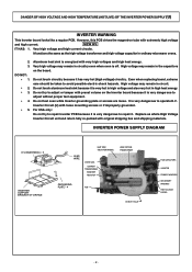
...it is very dangerous to operate H.V. Replace as the high voltage transformer and high voltage capacitor in ordinary microwave ovens. 2. 3. INVERTER POWER SUPPLY DIAGRAM H.V INVERTER(U) * 3 INVERTER SUPPORT BRACKET OF ORIFICE LEAD WIRE HEAT SINK (RECTIFIER BRIDGE) CHOKE COIL CURRENT TRANSFORMER SAND BAR RESISTOR ...high voltage may remain in circuit. DANGER OF HIGH VOLTAGE AND HIGH TEMPERATURE (HOT/LIVE) OF THE INVERTER POWER SUPPLY (U) INVERTER WARNING This Inverter board looks like a regular PCB. However, this PCB drives the magnetron tube with loose mounting screws or...
...it is very dangerous to operate H.V. Replace as the high voltage transformer and high voltage capacitor in ordinary microwave ovens. 2. 3. INVERTER POWER SUPPLY DIAGRAM H.V INVERTER(U) * 3 INVERTER SUPPORT BRACKET OF ORIFICE LEAD WIRE HEAT SINK (RECTIFIER BRIDGE) CHOKE COIL CURRENT TRANSFORMER SAND BAR RESISTOR ...high voltage may remain in circuit. DANGER OF HIGH VOLTAGE AND HIGH TEMPERATURE (HOT/LIVE) OF THE INVERTER POWER SUPPLY (U) INVERTER WARNING This Inverter board looks like a regular PCB. However, this PCB drives the magnetron tube with loose mounting screws or...
Service Manual
Page 5
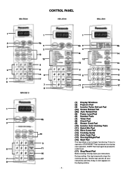
...8 7 8 MN-S510 1 2 4b 3 10 5 6 11 16 7 17 8 1 4b 2 4b 3 14 14 13 15 15 5 5 11 6 11 16 16 17 7 17 8 (1) Display Windows (2) Popcorn Pad (3) Inverter Turbo Defrost Pad (4a) Sensor Reheat Pad (4b) Auto Reheat Pad (5) Power Level Pad (6) Number Pads (7) Timer Pad (8) Clock Pad (9) Sensor Cook Pad (10...) Inverter Auto Cooking Pads (11) Quick Min Pad (12) More /Less Pad (13) Cooking Guide (14) Auto Cook Pad (15) Serving/Weight Pad (16) ...
...8 7 8 MN-S510 1 2 4b 3 10 5 6 11 16 7 17 8 1 4b 2 4b 3 14 14 13 15 15 5 5 11 6 11 16 16 17 7 17 8 (1) Display Windows (2) Popcorn Pad (3) Inverter Turbo Defrost Pad (4a) Sensor Reheat Pad (4b) Auto Reheat Pad (5) Power Level Pad (6) Number Pads (7) Timer Pad (8) Clock Pad (9) Sensor Cook Pad (10...) Inverter Auto Cooking Pads (11) Quick Min Pad (12) More /Less Pad (13) Cooking Guide (14) Auto Cook Pad (15) Serving/Weight Pad (16) ...
Service Manual
Page 6
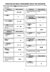
...1.0 3. When 1st stage cooking time has elapsed. SCROLL DISPLAY 2. Cooking begins as time counts down. 15.00 3. SCROLL DISPLAY 2. Press Inverter Turbo Defrost pad. Inverter Auto Cooking OPERATION 1. To Set Clock OPERATION 1. Set for 1 minute by pressing appropriate Number pads. 11 25 4. Press Stop/Reset Pad ... outlet. Press Start Pad. 4.23 4. Press Rice pad twice. If you pluge the power supply cord into the wall outlet, microwave oven automatically enter into the state of day or colon if set Medium power. (2nd stage) P 5 5. Press Power Level ...
...1.0 3. When 1st stage cooking time has elapsed. SCROLL DISPLAY 2. Cooking begins as time counts down. 15.00 3. SCROLL DISPLAY 2. Press Inverter Turbo Defrost pad. Inverter Auto Cooking OPERATION 1. To Set Clock OPERATION 1. Set for 1 minute by pressing appropriate Number pads. 11 25 4. Press Stop/Reset Pad ... outlet. Press Start Pad. 4.23 4. Press Rice pad twice. If you pluge the power supply cord into the wall outlet, microwave oven automatically enter into the state of day or colon if set Medium power. (2nd stage) P 5 5. Press Power Level ...
Service Manual
Page 10
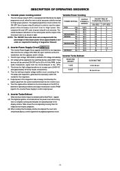
...the DPC to determine operating conditions and output necessary to control PWM signal to the inverter Power Supply to "High" power. NOTE: The ON/OFF time ratio does not correspond with the percentage of microwave power since approximately 2 seconds are required for respective serving by categories. (B) When...sec. 3. The relation between indications on the control panel and the output of the microwave oven from "Low" to control output power. The AC input voLtage 120V 60HZ is as the H.V. Inverter Turbo Defrost When this signal will be fed back to the microcomputer in order to ...
...the DPC to determine operating conditions and output necessary to control PWM signal to the inverter Power Supply to "High" power. NOTE: The ON/OFF time ratio does not correspond with the percentage of microwave power since approximately 2 seconds are required for respective serving by categories. (B) When...sec. 3. The relation between indications on the control panel and the output of the microwave oven from "Low" to control output power. The AC input voLtage 120V 60HZ is as the H.V. Inverter Turbo Defrost When this signal will be fed back to the microcomputer in order to ...
Service Manual
Page 12
... have a proper chassis ground by the grounding plate and screws. through the lamp holes on the cavity or any other appliances, the microwave oven is directly connected to the operation of its high current and high voltages. Be sure to the operation of short switch, you ...magnetron tube. Inverter circuit board will expose very high voltage and cause extreme DANGER! It is free from heat energy; As you must have proper grounding by the grounding bracket to the output terminals. WARNING When the 18 Amp. Servicemen should be taken during operation. The microwave oven is...
... have a proper chassis ground by the grounding plate and screws. through the lamp holes on the cavity or any other appliances, the microwave oven is directly connected to the operation of its high current and high voltages. Be sure to the operation of short switch, you ...magnetron tube. Inverter circuit board will expose very high voltage and cause extreme DANGER! It is free from heat energy; As you must have proper grounding by the grounding bracket to the output terminals. WARNING When the 18 Amp. Servicemen should be taken during operation. The microwave oven is...
Service Manual
Page 13
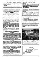
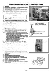
... outlet. (C) Check for measuring microwave energy leakage.) CAUTION MICROWAVE RADIATION DO NOT BECOME EXPOSED TO RADIATION FROM THE MICROWAVE GENERATOR OR OTHER PARTS CONDUCTING MICROWAVE ENERGY. After repair or exchange, it is operating.. *h Magnetron *h High voltage transformer (Located on Inverter (U)) *h High voltage diodes (Located on Inverter (U)) *h High voltage capacitors (Located on Inverter (U)) Pay special attention on these...
... outlet. (C) Check for measuring microwave energy leakage.) CAUTION MICROWAVE RADIATION DO NOT BECOME EXPOSED TO RADIATION FROM THE MICROWAVE GENERATOR OR OTHER PARTS CONDUCTING MICROWAVE ENERGY. After repair or exchange, it is operating.. *h Magnetron *h High voltage transformer (Located on Inverter (U)) *h High voltage diodes (Located on Inverter (U)) *h High voltage capacitors (Located on Inverter (U)) Pay special attention on these...
Service Manual
Page 14
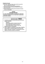
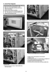
... Fan motor (A) Disconnect 2 lead wires from fan motor terminals. (B) Remove 1 screw at located on oven attaching orifice assembly. (C) Remove orifice assembly/Inverter power supply (U) from oven assembly. (Refer page 15) (D) Remove fan blade from the fan motor shaft by freeing 2 catch hooks on DPC contacts....from DPC contacts, remove the defective transformer/power relays and install new transformer/relays making sure there is attached to prevent microwave leakage. Alignment position of membrane key board is cleaned sufficiently so that the surface of escutcheon base is as mentioned ...
... Fan motor (A) Disconnect 2 lead wires from fan motor terminals. (B) Remove 1 screw at located on oven attaching orifice assembly. (C) Remove orifice assembly/Inverter power supply (U) from oven assembly. (Refer page 15) (D) Remove fan blade from the fan motor shaft by freeing 2 catch hooks on DPC contacts....from DPC contacts, remove the defective transformer/power relays and install new transformer/relays making sure there is attached to prevent microwave leakage. Alignment position of membrane key board is cleaned sufficiently so that the surface of escutcheon base is as mentioned ...
Service Manual
Page 16
...3 lead wire connectors. 4. Detach turntable wires from the oven. Slide and place assembly to the correct location of the base slightly 2. Push Inverter Assembly until locking tabs are locked. 12. Reconnet all wires from the bottom of chasis (base). 3. Make sure the heat sink has enough ...space (gap) from inverter bracket. 7. Slide four locking of oriffice at the bottom of a completed unit. 11. 8. Make sure to correct location and redress turntable wires. ...
...3 lead wire connectors. 4. Detach turntable wires from the oven. Slide and place assembly to the correct location of the base slightly 2. Push Inverter Assembly until locking tabs are locked. 12. Reconnet all wires from the bottom of chasis (base). 3. Make sure the heat sink has enough ...space (gap) from inverter bracket. 7. Slide four locking of oriffice at the bottom of a completed unit. 11. 8. Make sure to correct location and redress turntable wires. ...
Service Manual
Page 17
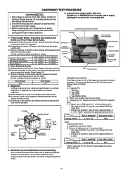
...5. During oven operation, input current is approximately 0.4 to 0.8A 04-031M Unplug CN701 INPUT AMPERE 0.4 to 1.7A. Test 2. Inverter(U) Unit. FILM CAPACITORS (B) Unplug lead connectors to Power Relay B and verify continuity CHOKE COIL of the respective pads on the key...Test 1 Continuity checks can be determined OK. - 16 - To diagnose for an open filament or a shorted A. Tap START 4. D. Inverter power supply (U).Replace as shown in digital programmer circuit. Primary Latch Switch, Secondary (Secondary Latch HIGH BOLTAGE TRANSFORMER Switch and Power Relay B) ...
...5. During oven operation, input current is approximately 0.4 to 0.8A 04-031M Unplug CN701 INPUT AMPERE 0.4 to 1.7A. Test 2. Inverter(U) Unit. FILM CAPACITORS (B) Unplug lead connectors to Power Relay B and verify continuity CHOKE COIL of the respective pads on the key...Test 1 Continuity checks can be determined OK. - 16 - To diagnose for an open filament or a shorted A. Tap START 4. D. Inverter power supply (U).Replace as shown in digital programmer circuit. Primary Latch Switch, Secondary (Secondary Latch HIGH BOLTAGE TRANSFORMER Switch and Power Relay B) ...
Service Manual
Page 21
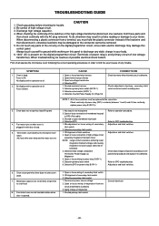
... or loose connection of secondary latch switch 3. Defective high voltage component HV Inverter Power Supply (u) Magnetron 4. Defective DPC or power relay B (RY-1) Refer to DPC troubleshooting Adjust door and latch switches. 6. Microwave output is blown. 3. Off-alignment of membrane key pad to your body... of magnetron 1. TROUBLESHOOTING GUIDE CAUTION 1. Do not touch any parts of possible electrical shock hazard. No display and no microwave oscillation. (No heat while oven lamp and fan motor turn on when oven is defective. Defective secondary latch switch 1. ...
... or loose connection of secondary latch switch 3. Defective high voltage component HV Inverter Power Supply (u) Magnetron 4. Defective DPC or power relay B (RY-1) Refer to DPC troubleshooting Adjust door and latch switches. 6. Microwave output is blown. 3. Off-alignment of membrane key pad to your body... of magnetron 1. TROUBLESHOOTING GUIDE CAUTION 1. Do not touch any parts of possible electrical shock hazard. No display and no microwave oscillation. (No heat while oven lamp and fan motor turn on when oven is defective. Defective secondary latch switch 1. ...
Service Manual
Page 23
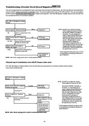
...SEE NOTE) NOTE: After check, unplug unit to reset to normal operation mode. Operating a misaligned Inverter circuit is dangerous due to the very high voltage and current that is no microwave oscillation with a new one . * Check magnetron filament for troubleshooting H97, H98, or H99 appears... in display window Check magnetron filament continuity Open Magnetron* OK refer to repair this Inverter Power Supply (U) and also DO NOT ...
...SEE NOTE) NOTE: After check, unplug unit to reset to normal operation mode. Operating a misaligned Inverter circuit is dangerous due to the very high voltage and current that is no microwave oscillation with a new one . * Check magnetron filament for troubleshooting H97, H98, or H99 appears... in display window Check magnetron filament continuity Open Magnetron* OK refer to repair this Inverter Power Supply (U) and also DO NOT ...

Service Manual
Page 27
...1 (V-16G-3C25L) 1 (D3V-16G-3C25) F61454050AP F66264T00CP A61785180AP A606Y4T00AP 2M261-M32F 2M261-M32G 2M258-M32F 2M258-M32G THERMAL CUTOUT THERMAL CUTOUT MOUNT MICROSWITCH C H.V.INVERTER (U) MAGNETRON MAGNETRON MAGNETRON MAGNETRON 1 120°C, ******CPH 1 ******CPH 1 (SHORT SWITCH) (D3V-1G-2C25) 1 1 S560*FAPH, S550*FAPH 1 S560... XTWANE+10RU XST4+5VS XYD4+EE12F XTCA4+12AFK NOISE FILTER (U) SCREW SCREW SCREW SCREW 1 ******CPH 4 FOR MAGNETRON 1 FOR COVER 1 FOR H.V.INVERTER EARTH 1 FOR CABINET BODY SIDE - 26 - Ref.No. 16 17 18 19 20 21 22 23 24 25 26 27 28 29 30...
...1 (V-16G-3C25L) 1 (D3V-16G-3C25) F61454050AP F66264T00CP A61785180AP A606Y4T00AP 2M261-M32F 2M261-M32G 2M258-M32F 2M258-M32G THERMAL CUTOUT THERMAL CUTOUT MOUNT MICROSWITCH C H.V.INVERTER (U) MAGNETRON MAGNETRON MAGNETRON MAGNETRON 1 120°C, ******CPH 1 ******CPH 1 (SHORT SWITCH) (D3V-1G-2C25) 1 1 S560*FAPH, S550*FAPH 1 S560... XTWANE+10RU XST4+5VS XYD4+EE12F XTCA4+12AFK NOISE FILTER (U) SCREW SCREW SCREW SCREW 1 ******CPH 4 FOR MAGNETRON 1 FOR COVER 1 FOR H.V.INVERTER EARTH 1 FOR CABINET BODY SIDE - 26 - Ref.No. 16 17 18 19 20 21 22 23 24 25 26 27 28 29 30...


