Data Sheet
Page 1
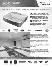
... speaker CONNECTIVITY (May require optional accessories) The Optoma EH319UST is crisp and clear, enhancing the effectiveness of presentations containing audio while the ECO+ power mode yields an impressive 6500 hours of lamp life. EH319UST is flexible and robust providing full network control support for popular management suites such as Crestron and PJ Link, along with 18000:1 contrast ratio Large, clear and shadow-free 100" image...
... speaker CONNECTIVITY (May require optional accessories) The Optoma EH319UST is crisp and clear, enhancing the effectiveness of presentations containing audio while the ECO+ power mode yields an impressive 6500 hours of lamp life. EH319UST is flexible and robust providing full network control support for popular management suites such as Crestron and PJ Link, along with 18000:1 contrast ratio Large, clear and shadow-free 100" image...
Data Sheet
Page 2
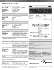
..., Auto Throw Ratio Projection Distance 0.25:1 (distance/width), ± 5% Variance 17.7"- 22.1" (0.45 - 0.56 m) Image Size (Diagonal) 80"-100" (2.03-2.54 m) Diagonal 16:9 Projection Lens F/2.4; 1080P UST PROJECTOR - f=3.72 mm, Fixed Zoom Zoom Fixed Zoom Audio One 16-Watt speaker Noise Level Min 29dB-Max 36dB Remote Control IR remote Operating Temperature 41-104°F (5- 40°C), 85% max humidity Power Supply AC input 100 - 240V, 50 - 60Hz, auto-switching Power Consumption 320W Bright Mode / 260W Eco mode...
..., Auto Throw Ratio Projection Distance 0.25:1 (distance/width), ± 5% Variance 17.7"- 22.1" (0.45 - 0.56 m) Image Size (Diagonal) 80"-100" (2.03-2.54 m) Diagonal 16:9 Projection Lens F/2.4; 1080P UST PROJECTOR - f=3.72 mm, Fixed Zoom Zoom Fixed Zoom Audio One 16-Watt speaker Noise Level Min 29dB-Max 36dB Remote Control IR remote Operating Temperature 41-104°F (5- 40°C), 85% max humidity Power Supply AC input 100 - 240V, 50 - 60Hz, auto-switching Power Consumption 320W Bright Mode / 260W Eco mode...

User manual
Page 2
... 5: Adjusting the tilt (horizontal keystone 18 Installing the whiteboard...19 Installing the TouchBeam module...20 Step 1: Mounting the TouchBeam module 20 Step 2: Install Utility Software...22 Step 3: Initial Setup...23 Step 4: Operation Mode...24 Step 5: TouchBeam Alignment...25 Step 6: Touch Area Setting...28 Step 7: Calibration...30 Step 8: Touch Sensitivity...31 Step 9: Troubleshooting Viewer...32 Appendix...33 Troubleshooting...33 Interactive cable layout...38 Distance Calculator ...39 Specification...
... 5: Adjusting the tilt (horizontal keystone 18 Installing the whiteboard...19 Installing the TouchBeam module...20 Step 1: Mounting the TouchBeam module 20 Step 2: Install Utility Software...22 Step 3: Initial Setup...23 Step 4: Operation Mode...24 Step 5: TouchBeam Alignment...25 Step 6: Touch Area Setting...28 Step 7: Calibration...30 Step 8: Touch Sensitivity...31 Step 9: Troubleshooting Viewer...32 Appendix...33 Troubleshooting...33 Interactive cable layout...38 Distance Calculator ...39 Specification...
User manual
Page 3
Use a standard USB cable (maximum length: 5m). Do not allow liquid or foreign material to the whiteboard. Precautions The IR camera on the projector receives infrared signals from the TouchBeam module which is required. Warning - Maintenance: Gently clean the optical port with a thin invisible IR light. When a finger or stylus breaks the TouchBeam, IR light reflects to the IR...
Use a standard USB cable (maximum length: 5m). Do not allow liquid or foreign material to the whiteboard. Precautions The IR camera on the projector receives infrared signals from the TouchBeam module which is required. Warning - Maintenance: Gently clean the optical port with a thin invisible IR light. When a finger or stylus breaks the TouchBeam, IR light reflects to the IR...

User manual
Page 4
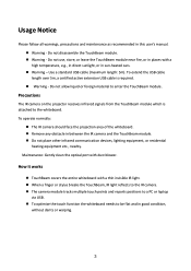
Package Overview TouchBeam module 2x (M2 6mm) screws 2x (M6 6mm) screws Interactive cable power cable 2x Alignment sticker sticjestickers TouchBeam bracket mounting plate Double sided tape TouchBeam mounting plate 5m USB cable 2x Passive pens CD user manual software 4
Package Overview TouchBeam module 2x (M2 6mm) screws 2x (M6 6mm) screws Interactive cable power cable 2x Alignment sticker sticjestickers TouchBeam bracket mounting plate Double sided tape TouchBeam mounting plate 5m USB cable 2x Passive pens CD user manual software 4

User manual
Page 5
... recommend using the interactive function install the projector so that the power supply and wiring work for the installation location of the projector We recommend to keep source cable length less than +/-3 degrees vertically and horizontal in relation to direct sunlight, the interactive function may not operate correctly. 5 Before Installation - Environment Check Before setting up and installing the projector and TouchBeam module ensure that the projected image is installed under...
... recommend using the interactive function install the projector so that the power supply and wiring work for the installation location of the projector We recommend to keep source cable length less than +/-3 degrees vertically and horizontal in relation to direct sunlight, the interactive function may not operate correctly. 5 Before Installation - Environment Check Before setting up and installing the projector and TouchBeam module ensure that the projected image is installed under...

User manual
Page 6
... meet the following ways 1. Mount the projector and TouchBeam module to the whiteboard Image area Image area 6 Mount the projector to the wall and attached the TouchBeam module to the wall 2. The screen surface is a flat, smooth surface with screws If the projection surface meets the criteria above, the projector and TouchBeam module can either be installed in one of more...
... meet the following ways 1. Mount the projector and TouchBeam module to the whiteboard Image area Image area 6 Mount the projector to the wall and attached the TouchBeam module to the wall 2. The screen surface is a flat, smooth surface with screws If the projection surface meets the criteria above, the projector and TouchBeam module can either be installed in one of more...

User manual
Page 12
Installation guide Installation workflow o Install the projector mount (See mount installation guide) o Attach the projector to mount (See mount installation guide) o Connect sources to the projector o Adjust projected images (See mount installation guide) o Install the whiteboard (See whiteboard installation guide) o Install the TouchBeam module Attach to board Connect to projector / PC Calibrate Note: If the whiteboard is already installed please see page 36. 12
Installation guide Installation workflow o Install the projector mount (See mount installation guide) o Attach the projector to mount (See mount installation guide) o Connect sources to the projector o Adjust projected images (See mount installation guide) o Install the whiteboard (See whiteboard installation guide) o Install the TouchBeam module Attach to board Connect to projector / PC Calibrate Note: If the whiteboard is already installed please see page 36. 12

User manual
Page 16
... 4: Adjusting the projected image size Loosen the two bolts on the fine length adjustor - Fig 4C Tighten the fixing bolt on the fine adjuster - Fig 4D Adjust highlighted bolt to move the projector closer to the screen To increase the projected image size, loosen the bolt anticlockwise using one of the allen keys provided to fine adjust the throw distance - Tighten...
... 4: Adjusting the projected image size Loosen the two bolts on the fine length adjustor - Fig 4C Tighten the fixing bolt on the fine adjuster - Fig 4D Adjust highlighted bolt to move the projector closer to the screen To increase the projected image size, loosen the bolt anticlockwise using one of the allen keys provided to fine adjust the throw distance - Tighten...

User manual
Page 25
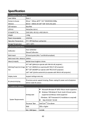
Step 4: Operation Mode Windows 7 and Windows 8 operating systems support multi-point touch control. Users can select default Touch Mode ( ) for multi-point touch, Or switch to Pen Mode ( ) when using the light pen (IR pen). Please note: Windows XP and MAC operating systems only support single-point touch 25
Step 4: Operation Mode Windows 7 and Windows 8 operating systems support multi-point touch control. Users can select default Touch Mode ( ) for multi-point touch, Or switch to Pen Mode ( ) when using the light pen (IR pen). Please note: Windows XP and MAC operating systems only support single-point touch 25

User manual
Page 26
LED indicator Red LED Description -- Rotate the black and grey adjustment knobs clockwise until they stop 26 Step 5: TouchBeam Alignment 1. IR laser ON Blinking Visible light ON (IR Laser OFF, touch disabled) Solid Error of LD module occurred. 2. Connect PC and Projector via USB cable 3. Press the button to switch to visible light mode (The Red LED will blink continuously) Mode IR Laser mode Visible light mode Error Blue LED Solid Solid --
LED indicator Red LED Description -- Rotate the black and grey adjustment knobs clockwise until they stop 26 Step 5: TouchBeam Alignment 1. IR laser ON Blinking Visible light ON (IR Laser OFF, touch disabled) Solid Error of LD module occurred. 2. Connect PC and Projector via USB cable 3. Press the button to switch to visible light mode (The Red LED will blink continuously) Mode IR Laser mode Visible light mode Error Blue LED Solid Solid --

User manual
Page 28
Put top cover back on and tighten the screws. 28 7. IR laser ON Blinking Visible light ON (IR Laser OFF, touch disabled) Always ON Error of LD module occurred. 8. LED indicator Red LED Description -- Press the button again to switch back to IR mode (The Blue LED will stay solid) Mode IR Laser mode Visible light mode Error Blue LED Solid Solid --
Put top cover back on and tighten the screws. 28 7. IR laser ON Blinking Visible light ON (IR Laser OFF, touch disabled) Always ON Error of LD module occurred. 8. LED indicator Red LED Description -- Press the button again to switch back to IR mode (The Blue LED will stay solid) Mode IR Laser mode Visible light mode Error Blue LED Solid Solid --
User manual
Page 29
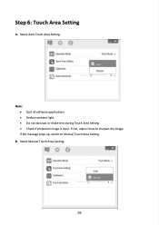
If not, adjust focus to sharpen the image If fail message pops up, switch to Manual Touch Area Setting. Select Manual Touch Area Setting: 29 Step 6: Touch Area Setting A. B. Select Auto Touch Area Setting: Note: Quit all software applications Reduce ambient light Do not obstruct or shake lens during Touch Area Setting Check if projection image is clear.
If not, adjust focus to sharpen the image If fail message pops up, switch to Manual Touch Area Setting. Select Manual Touch Area Setting: 29 Step 6: Touch Area Setting A. B. Select Auto Touch Area Setting: Note: Quit all software applications Reduce ambient light Do not obstruct or shake lens during Touch Area Setting Check if projection image is clear.

User manual
Page 31
Select Auto Calibration Note: If the fail message pops up on screen, switch to troubleshoot the issues. Close all software applications Reduce ambient light Do not obstruct or shake lens during calibration Check if projection image is suggested for better accuracy. 31 B. If not, adjust focus to sharpen the image If the Auto Calibration fail message still pops up , follow the steps shown below to Manual Calibration. Select Manual Calibration: Note: Manual Calibration is clear. Step 7: Calibration A.
Select Auto Calibration Note: If the fail message pops up on screen, switch to troubleshoot the issues. Close all software applications Reduce ambient light Do not obstruct or shake lens during calibration Check if projection image is suggested for better accuracy. 31 B. If not, adjust focus to sharpen the image If the Auto Calibration fail message still pops up , follow the steps shown below to Manual Calibration. Select Manual Calibration: Note: Manual Calibration is clear. Step 7: Calibration A.

User manual
Page 34
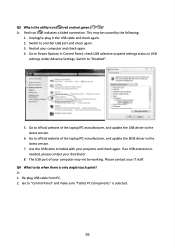
... Windows system cannot identify the USB device? Unplug USB cable from PC; Unplug/re-plug in USB settings under Advance Settings. Switch to Power Options in Control Panel, check USB selective suspend settings status in the USB cable and check again. 2. If a USB extension is connected to the projector? or 2. Choose Hard disk as top priority, save the change and reboot PC. Go to BIOS setup page of the laptop/PC manufacturer, and update the USB driver...
... Windows system cannot identify the USB device? Unplug USB cable from PC; Unplug/re-plug in USB settings under Advance Settings. Switch to Power Options in Control Panel, check USB selective suspend settings status in the USB cable and check again. 2. If a USB extension is connected to the projector? or 2. Choose Hard disk as top priority, save the change and reboot PC. Go to BIOS setup page of the laptop/PC manufacturer, and update the USB driver...
User manual
Page 35
... selected. 35 Unplug/re-plug in Control Panel; Switch to the latest version. 7. Go to official website of your projector and check again. If an USB extension is the utility icon ( ) red and not green ( / )? Use the USB cable included with your computer may be working. check USB selective suspend settings status in USB settings under Advance Settings. Please contact your computer and check again. 4. Q3 Why is needed, please...
... selected. 35 Unplug/re-plug in Control Panel; Switch to the latest version. 7. Go to official website of your projector and check again. If an USB extension is the utility icon ( ) red and not green ( / )? Use the USB cable included with your computer may be working. check USB selective suspend settings status in USB settings under Advance Settings. Please contact your computer and check again. 4. Q3 Why is needed, please...
User manual
Page 36
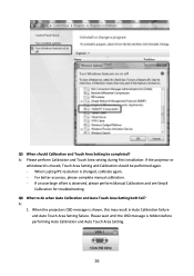
... Auto Calibration and Auto Touch Area Setting both fail? A: 1. When Laptop/PC resolution is observed, please perform Manual Calibration and see Step 8 Calibration for troubleshooting. If an overlarge offset is changed, calibrate again. - Please wait until the OSD message is shown, this may result in Auto Calibration failure and Auto Touch Area Setting failure. A: Please perform Calibration and Touch Area setting during first installation. When the projectors...
... Auto Calibration and Auto Touch Area Setting both fail? A: 1. When Laptop/PC resolution is observed, please perform Manual Calibration and see Step 8 Calibration for troubleshooting. If an overlarge offset is changed, calibrate again. - Please wait until the OSD message is shown, this may result in Auto Calibration failure and Auto Touch Area Setting failure. A: Please perform Calibration and Touch Area setting during first installation. When the projectors...
User manual
Page 37
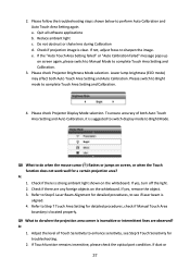
a. Check if projection image is aligned. 4. If not, adjust focus to complete Touch Area Setting and Calibration. 4. Please check Projector Brightness Mode selection. If yes, turn off the light. 2. A: 1. Reduce ambient light c. Please switch to Bright mode to sharpen the image. Please check Projector Display Mode selection. If Touch function remains insensitive, please check the optical port condition. Please follow the troubleshooting steps shown below to Step 7 Touch Area Setting for troubleshooting. 2. If the "Auto Touch...
a. Check if projection image is aligned. 4. If not, adjust focus to complete Touch Area Setting and Calibration. 4. Please check Projector Brightness Mode selection. If yes, turn off the light. 2. A: 1. Reduce ambient light c. Please switch to Bright mode to sharpen the image. Please check Projector Display Mode selection. If Touch function remains insensitive, please check the optical port condition. Please follow the troubleshooting steps shown below to Step 7 Touch Area Setting for troubleshooting. 2. If the "Auto Touch...

User manual
Page 38
A: Touch accuracy may be impacted when the Windows default display has been changed. 1. particles are observed, gently clean the optical port with dust blower. Go to do when the touch function is not accurate? Select "Smaller - 100%(Default) " and click "Apply". 38 Q10 What to the setting page 2.
A: Touch accuracy may be impacted when the Windows default display has been changed. 1. particles are observed, gently clean the optical port with dust blower. Go to do when the touch function is not accurate? Select "Smaller - 100%(Default) " and click "Apply". 38 Q10 What to the setting page 2.
User manual
Page 42
Specification I /O Port Interactive Jack x1 ID Size(W*L*H) Weight 150.0 (W) x 50.0 (L) x 40.0 (H) mm TouchBeam Touch Module Laser Safety Class 1 Curtain to Screen Distance LED Indicator 20mm ~ 100mm @75"~115" XGA/WXGA/1080p 40mm ~ 100mm @ 120"~140" 16:6 ultra-wide Blue/Red I .
Specification I /O Port Interactive Jack x1 ID Size(W*L*H) Weight 150.0 (W) x 50.0 (L) x 40.0 (H) mm TouchBeam Touch Module Laser Safety Class 1 Curtain to Screen Distance LED Indicator 20mm ~ 100mm @75"~115" XGA/WXGA/1080p 40mm ~ 100mm @ 120"~140" 16:6 ultra-wide Blue/Red I .


