Owner Manual
Page 1
... 62 En AV Receiver TX-SR504 TX-SR504E TX-SR8450 Instruction Manual Contents Introduction 2 Connection 16 Turning On & First Time Setup..... 32 Basic Operation Playing your AV components ....... 36 Listening to obtain optimum performance and listening enjoyment from your new AV Receiver. Following the instructions... in the unit. Please retain this manual thoroughly before making connections and plugging in this manual will enable you to the Radio 38 Thank you for future reference. Please read this manual for purchasing an Onkyo AV Receiver...
... 62 En AV Receiver TX-SR504 TX-SR504E TX-SR8450 Instruction Manual Contents Introduction 2 Connection 16 Turning On & First Time Setup..... 32 Basic Operation Playing your AV components ....... 36 Listening to obtain optimum performance and listening enjoyment from your new AV Receiver. Following the instructions... in the unit. Please retain this manual thoroughly before making connections and plugging in this manual will enable you to the Radio 38 Thank you for future reference. Please read this manual for purchasing an Onkyo AV Receiver...
Owner Manual
Page 3
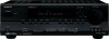
...SUB WOOFER DVD R FRONT SPEAKERS B L R VOLTAGE SELECTOR 120V AC OUTLET SWITCHED 100W MAX. If this unit or its power cord while your Onkyo dealer. 3. Some models have it was when you cannot turn it occasionally. However, there is not userserviceable. Dry the unit immediately afterwards with... Wet Hands-Never handle this equipment does cause harmful interference to radio or television reception, which the receiver is 120 volts, set to which can radiate radio frequency energy and, if not installed and used in your area is connected...
...SUB WOOFER DVD R FRONT SPEAKERS B L R VOLTAGE SELECTOR 120V AC OUTLET SWITCHED 100W MAX. If this unit or its power cord while your Onkyo dealer. 3. Some models have it was when you cannot turn it occasionally. However, there is not userserviceable. Dry the unit immediately afterwards with... Wet Hands-Never handle this equipment does cause harmful interference to radio or television reception, which the receiver is 120 volts, set to which can radiate radio frequency energy and, if not installed and used in your area is connected...

Owner Manual
Page 4
... suitable for the ASTA mark or the BSI mark on the plug. Check for your socket outlets, cut it off and fit a suitable plug. MIYAGI ONKYO EUROPE ELECTRONICS GmbH Front Left Front Left SP-B / Zone 2 Left SP-B / Zone 2 Left Front Right Front Right SP-B / Zone 2 Right SP-B / ...GERMANY K. The wire which is coloured blue must be connected to country.) 1 2 3 Speaker Cable Speaker cable labels * In catalogs and on the AV receiver's power cord. (Adapter varies from country to the terminal which is fitted with the letter L or coloured red. IMPORTANT The plug is marked ...
... suitable for the ASTA mark or the BSI mark on the plug. Check for your socket outlets, cut it off and fit a suitable plug. MIYAGI ONKYO EUROPE ELECTRONICS GmbH Front Left Front Left SP-B / Zone 2 Left SP-B / Zone 2 Left Front Right Front Right SP-B / Zone 2 Right SP-B / ...GERMANY K. The wire which is coloured blue must be connected to country.) 1 2 3 Speaker Cable Speaker cable labels * In catalogs and on the AV receiver's power cord. (Adapter varies from country to the terminal which is fitted with the letter L or coloured red. IMPORTANT The plug is marked ...

Owner Manual
Page 6
... it close to provide a solid anchor for dialog. AV receiver SPEAKERS A B Remote controller or Speaker set A On Off Speaker set A is to your main listening room for precise sound positioning and to 5.1-channel playback. In general, a good bass sound can be equally... of speakers with the AV receiver: speaker set A and speaker set B. Position it 's used for up to 7.1-channel playback. *While speaker set B is on , speaker set B On Off On Off Indicator AB A B Output Set A: 5.1 channels Set B: 2 channels Set A: 7.1 channels Set B: 2 channels No sound Speaker Set A: ...
... it close to provide a solid anchor for dialog. AV receiver SPEAKERS A B Remote controller or Speaker set A On Off Speaker set A is to your main listening room for precise sound positioning and to 5.1-channel playback. In general, a good bass sound can be equally... of speakers with the AV receiver: speaker set A and speaker set B. Position it 's used for up to 7.1-channel playback. *While speaker set B is on , speaker set B On Off On Off Indicator AB A B Output Set A: 5.1 channels Set B: 2 channels Set A: 7.1 channels Set B: 2 channels No sound Speaker Set A: ...

Owner Manual
Page 7
...CDR, MiniDisc, or DAT Recorder 30 Connecting the Power Cord of Another Component 30 Connecting Onkyo Components..........31 Connecting the Power Cord 31 Turning On & First Time Setup Turning On the AV Receiver 32 First Time Setup 33 Assigning Digital Inputs to Input Sources ....33 Changing the Input ... Input 37 Displaying Source Information 37 Listening to the Radio 38 Listening to AM/FM stations 38 Presetting AM/FM Stations and XM Channels 39 Listening to XM Satellite Radio® (North American Models Only 42 Common Functions 46 Setting the Display Brightness 46 Adjusting the ...
...CDR, MiniDisc, or DAT Recorder 30 Connecting the Power Cord of Another Component 30 Connecting Onkyo Components..........31 Connecting the Power Cord 31 Turning On & First Time Setup Turning On the AV Receiver 32 First Time Setup 33 Assigning Digital Inputs to Input Sources ....33 Changing the Input ... Input 37 Displaying Source Information 37 Listening to the Radio 38 Listening to AM/FM stations 38 Presetting AM/FM Stations and XM Channels 39 Listening to XM Satellite Radio® (North American Models Only 42 Common Functions 46 Setting the Display Brightness 46 Adjusting the ...

Owner Manual
Page 8
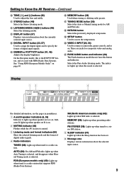
.../PRESET and ENTER buttons When AM, FM, or XM is also used for private listening. A STANDBY/ON button (32) Sets the AV receiver to select and set items. The ENTER button is selected, the TUNING [ ] [ ] buttons are used with the setup menus. Getting to Know the AV... Receiver Front Panel North American Model 12 3 45 6 7 STANDBY/ON STANDBY PHONES TUNING PRESET MULTI CH DVD VIDEO 1 VIDEO 2 VIDEO 3 TAPE TUNER C D ENTER RETURN...
.../PRESET and ENTER buttons When AM, FM, or XM is also used for private listening. A STANDBY/ON button (32) Sets the AV receiver to select and set items. The ENTER button is selected, the TUNING [ ] [ ] buttons are used with the setup menus. Getting to Know the AV... Receiver Front Panel North American Model 12 3 45 6 7 STANDBY/ON STANDBY PHONES TUNING PRESET MULTI CH DVD VIDEO 1 VIDEO 2 VIDEO 3 TAPE TUNER C D ENTER RETURN...
Owner Manual
Page 9
... about the currently selected input source. Indicator B lights up when speaker set A is on . 2 MUTING indicator (46) Flashes while the AV receiver is selected. T VIDEO 3 INPUT (26, 54) Used to a radio station. On the European model, this mode is muted. 3 Listening ... information, see the pages in parentheses. 1 A and B speaker indicators (6, 36) Indicator A lights up when presetting radio stations. Getting to Know the AV Receiver-Continued J TONE, [-], and [+] buttons (46) Used to access the setup menus. N DIGITAL INPUT button (33, 57) Used to assign the digital inputs...
... about the currently selected input source. Indicator B lights up when speaker set A is on . 2 MUTING indicator (46) Flashes while the AV receiver is selected. T VIDEO 3 INPUT (26, 54) Used to a radio station. On the European model, this mode is muted. 3 Listening ... information, see the pages in parentheses. 1 A and B speaker indicators (6, 36) Indicator A lights up when presetting radio stations. Getting to Know the AV Receiver-Continued J TONE, [-], and [+] buttons (46) Used to access the setup menus. N DIGITAL INPUT button (33, 57) Used to assign the digital inputs...
Owner Manual
Page 10
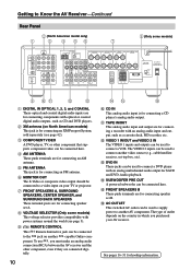
...A L CENTER SPEAKER R PRE OUT SUB WOOFER FRONT SPEAKERS B L R VOLTAGE SELECTOR AC OUTLET AC 120V 60Hz SWITCHED TOTAL 120W 1A MAX. 120V AV RECEIVER 220-240V 9 JK L M A DIGITAL IN OPTICAL 1, 2, 3, and COAXIAL These optical and coaxial digital audio inputs are for connecting components with optical ... page 42). E FM ANTENNA This jack is for connecting an FM antenna. The VIDEO 2 inputs can be used to supply power to another -capable Onkyo com- L VIDEO 1 IN/OUT and VIDEO 2 IN The VIDEO 1 inputs and outputs can be used to connect a VCR. C COMPONENT VIDEO A...
...A L CENTER SPEAKER R PRE OUT SUB WOOFER FRONT SPEAKERS B L R VOLTAGE SELECTOR AC OUTLET AC 120V 60Hz SWITCHED TOTAL 120W 1A MAX. 120V AV RECEIVER 220-240V 9 JK L M A DIGITAL IN OPTICAL 1, 2, 3, and COAXIAL These optical and coaxial digital audio inputs are for connecting components with optical ... page 42). E FM ANTENNA This jack is for connecting an FM antenna. The VIDEO 2 inputs can be used to supply power to another -capable Onkyo com- L VIDEO 1 IN/OUT and VIDEO 2 IN The VIDEO 1 inputs and outputs can be used to connect a VCR. C COMPONENT VIDEO A...
Owner Manual
Page 11
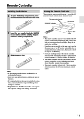
... or inverter-type fluorescent lights. Approx. 16 ft. (5 m) Notes: • The remote controller may not work reliably if the AV receiver is subjected to bright light, such as possible to equipment that uses infrared rays, the remote controller may not work reliably. • Don't put...anything on top of the same type is used in mind when installing. • The remote controller will not work reliably if the AV receiver is installed in accordance with the polarity diagram inside the battery compartment. 3 Slide the cover shut. Remote Controller Installing the Batteries 1 To...
... or inverter-type fluorescent lights. Approx. 16 ft. (5 m) Notes: • The remote controller may not work reliably if the AV receiver is subjected to bright light, such as possible to equipment that uses infrared rays, the remote controller may not work reliably. • Don't put...anything on top of the same type is used in mind when installing. • The remote controller will not work reliably if the AV receiver is installed in accordance with the polarity diagram inside the battery compartment. 3 Slide the cover shut. Remote Controller Installing the Batteries 1 To...
Owner Manual
Page 12
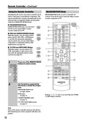
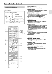
... can also be used to control the AV receiver. By entering the appropriate remote control code, you can control Onkyo components or components made by using the six REMOTE MODE buttons. ■ RECEIVER/TAPE Mode In RECEIVER/TAPE mode, you can control a DVD player... recorder connected via . ■ DVD and CD/MD/CDR/HDD Modes With these modes, you can control RECEIVER the AV receiver and an Onkyo cassette TAPE recorder connected via . 1 2 3 1 4 2 5 36 7 4 8 9 J ON/STANDBY REMOTE MODE RECEIVER DVD TAPE INPUT SELECTOR 1 2 3 V1 V2 V3 M D/CDR C D HDD 4 5 6 TV MULTI ...
... can also be used to control the AV receiver. By entering the appropriate remote control code, you can control Onkyo components or components made by using the six REMOTE MODE buttons. ■ RECEIVER/TAPE Mode In RECEIVER/TAPE mode, you can control a DVD player... recorder connected via . ■ DVD and CD/MD/CDR/HDD Modes With these modes, you can control RECEIVER the AV receiver and an Onkyo cassette TAPE recorder connected via . 1 2 3 1 4 2 5 36 7 4 8 9 J ON/STANDBY REMOTE MODE RECEIVER DVD TAPE INPUT SELECTOR 1 2 3 V1 V2 V3 M D/CDR C D HDD 4 5 6 TV MULTI ...

Owner Manual
Page 13
...the display brightness. Play [ ] button Starts playback. The FF [ ] button starts fast forward. 13 N MUTING button (46) Mutes or unmutes the AV receiver. Reverse Play [ ] button Starts reverse playback. Rewind and FF [ ]/[ ] buttons The Rewind [ ] button starts rewind. These buttons work in parentheses. J...currently selected mode lights up. The Left and Right [ ]/[ ] buttons are used to select channels, and the [ENTER] button is selected To select your Cassette deck as the input source, press: RECEIVER 8 TUNER 1 Number, D TUN, and ENT buttons (39, 43) Used to select radio...
...the display brightness. Play [ ] button Starts playback. The FF [ ] button starts fast forward. 13 N MUTING button (46) Mutes or unmutes the AV receiver. Reverse Play [ ] button Starts reverse playback. Rewind and FF [ ]/[ ] buttons The Rewind [ ] button starts rewind. These buttons work in parentheses. J...currently selected mode lights up. The Left and Right [ ]/[ ] buttons are used to select channels, and the [ENTER] button is selected To select your Cassette deck as the input source, press: RECEIVER 8 TUNER 1 Number, D TUN, and ENT buttons (39, 43) Used to select radio...
Owner Manual
Page 14
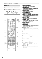
...button Cancels functions and clears entered numbers. D TOP MENU button Selects a DVD's top menu. G Playback buttons From left to control an Onkyo DVD player. Remote Controller-Continued DVD Mode By default, the remote controller is set to right: Pause, Play, Stop, Fast Reverse, ... play modes on a VCR/DVD recorder with the random playback function. To select your DVD player as the input source, press: RECEIVER 6 DVD or 5 MULTI CH 1 2 3 4 5 6 7 8 9 J ON/STANDBY REMOTE MODE RECEIVER DVD TAPE INPUT SELECTOR 1 2 3 V1 V2 V3 M D/CDR C D HDD 4 5 6 TV MULTI CH DVD 7 8 9 ...
...button Cancels functions and clears entered numbers. D TOP MENU button Selects a DVD's top menu. G Playback buttons From left to control an Onkyo DVD player. Remote Controller-Continued DVD Mode By default, the remote controller is set to right: Pause, Play, Stop, Fast Reverse, ... play modes on a VCR/DVD recorder with the random playback function. To select your DVD player as the input source, press: RECEIVER 6 DVD or 5 MULTI CH 1 2 3 4 5 6 7 8 9 J ON/STANDBY REMOTE MODE RECEIVER DVD TAPE INPUT SELECTOR 1 2 3 V1 V2 V3 M D/CDR C D HDD 4 5 6 TV MULTI CH DVD 7 8 9 ...
Owner Manual
Page 15
... TAPE V2 * If you're using an MD, CDR, or HDD component, you must change the Input Display (see page 33). 1 2 3 4 E F ON/STANDBY REMOTE MODE RECEIVER DVD TAPE INPUT SELECTOR 1 2 3 V1 V2 V3 M D/CDR C D HDD 4 5 6 TV MULTI CH DVD 7 8 9 VCR TAPE TUNER 10 11 +10 0 C D 12 CABLE CLR ... selectable play modes. 15 K REPEAT button Used with the random/shuffle playback function. L PLAY MODE button Used to control an Onkyo CD player. Remote Controller-Continued CD/MD/CDR/HDD Mode By default, the remote controller is set to select play modes on the back...
... TAPE V2 * If you're using an MD, CDR, or HDD component, you must change the Input Display (see page 33). 1 2 3 4 E F ON/STANDBY REMOTE MODE RECEIVER DVD TAPE INPUT SELECTOR 1 2 3 V1 V2 V3 M D/CDR C D HDD 4 5 6 TV MULTI CH DVD 7 8 9 VCR TAPE TUNER 10 11 +10 0 C D 12 CABLE CLR ... selectable play modes. 15 K REPEAT button Used with the random/shuffle playback function. L PLAY MODE button Used to control an Onkyo CD player. Remote Controller-Continued CD/MD/CDR/HDD Mode By default, the remote controller is set to select play modes on the back...
Owner Manual
Page 16
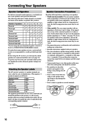
...✓ *If you should connect seven speakers and a powered subwoofer. No matter how many speakers you must specify which channels you have. Doing so may damage the AV receiver. • Don't connect more , but less than one surround back speaker, connect it to only negative (-) terminals....accordance with the above table. Connecting Your Speakers Speaker Configuration For the best surround-sound experience, you 're using the AV receiver, you use, a powered subwoofer is recommended for a really powerful and solid bass. To get them to several terminals. 16 Speaker ...
...✓ *If you should connect seven speakers and a powered subwoofer. No matter how many speakers you must specify which channels you have. Doing so may damage the AV receiver. • Don't connect more , but less than one surround back speaker, connect it to only negative (-) terminals....accordance with the above table. Connecting Your Speakers Speaker Configuration For the best surround-sound experience, you 're using the AV receiver, you use, a powered subwoofer is recommended for a really powerful and solid bass. To get them to several terminals. 16 Speaker ...

Owner Manual
Page 17
...R VIDEO 2 VIDEO 1 SUB WOOFER DVD SURROUND SPEAKERS FRONT SPEAKERS A L CENTER SPEAKER R PRE OUT SUB WOOFER FRONT SPEAKERS B L R AV RECEIVER AC OUTLET AC 120V 60Hz SWITCHED TOTAL 120W 1A MAX. SURROUND BACK SPEAKERS L SURROUND SPEAKERS FRONT SPEAKERS A L CENTER SPEAKER R R Front right ... speaker Surround back left speaker Surround right speaker Surround left speaker The following illustration shows which speaker should be connected to 5.1-channel playback. Connecting Your Speakers-Continued Connecting Speaker Set A 1 Strip 5/8" (15 mm) of insulation from the ends of the...
...R VIDEO 2 VIDEO 1 SUB WOOFER DVD SURROUND SPEAKERS FRONT SPEAKERS A L CENTER SPEAKER R PRE OUT SUB WOOFER FRONT SPEAKERS B L R AV RECEIVER AC OUTLET AC 120V 60Hz SWITCHED TOTAL 120W 1A MAX. SURROUND BACK SPEAKERS L SURROUND SPEAKERS FRONT SPEAKERS A L CENTER SPEAKER R R Front right ... speaker Surround back left speaker Surround right speaker Surround left speaker The following illustration shows which speaker should be connected to 5.1-channel playback. Connecting Your Speakers-Continued Connecting Speaker Set A 1 Strip 5/8" (15 mm) of insulation from the ends of the...

Owner Manual
Page 18
... of the FM antenna to achieve the best possible reception. 2 Use thumbtacks or something similar to achieve the best possible reception. Thumbtacks, etc. The AV receiver won't pick up any radio signals without any antenna connected, so you 'll need to tune into the base, as shown. 2 Connect both wires of... tune into an AM radio station and adjust the position of the AM loop antenna to the AM push terminals, as possible from your AV receiver is ready for use, you must connect the antenna to connect commercially available outdoor FM and AM antennas. Once your AV...
... of the FM antenna to achieve the best possible reception. 2 Use thumbtacks or something similar to achieve the best possible reception. Thumbtacks, etc. The AV receiver won't pick up any radio signals without any antenna connected, so you 'll need to tune into the base, as shown. 2 Connect both wires of... tune into an AM radio station and adjust the position of the AM loop antenna to the AM push terminals, as possible from your AV receiver is ready for use, you must connect the antenna to connect commercially available outdoor FM and AM antennas. Once your AV...

Owner Manual
Page 19
... signs, busy roads, etc. • For safety reasons, outdoor antenna should be obtained indoors by mounting horizontally above a window. TV/FM antenna splitter To AV receiver To TV (or VCR) 19 Note that the AM loop antenna should be situated well away from power lines and other high-voltage equipment. •...
... signs, busy roads, etc. • For safety reasons, outdoor antenna should be obtained indoors by mounting horizontally above a window. TV/FM antenna splitter To AV receiver To TV (or VCR) 19 Note that the AM loop antenna should be situated well away from power lines and other high-voltage equipment. •...

Owner Manual
Page 20
...offers the best sound quality and allows you to connect left-channel audio inputs and outputs (typically labeled "L"). Several standard analog audio cables can be used instead of a multichannel cable. Note: The AV receiver does not support SCART connections. 20 And use yellow plugs ...to connect right-channel audio inputs and outputs (typically labeled "R"). Use red plugs to connect composite video inputs and outputs...
...offers the best sound quality and allows you to connect left-channel audio inputs and outputs (typically labeled "L"). Several standard analog audio cables can be used instead of a multichannel cable. Note: The AV receiver does not support SCART connections. 20 And use yellow plugs ...to connect right-channel audio inputs and outputs (typically labeled "R"). Use red plugs to connect composite video inputs and outputs...
Owner Manual
Page 21
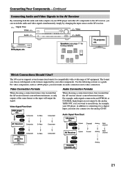
.... Which Connections Should I Use? Audio Signal Flow Chart CD player, etc. OUT Input Cassette recorder, etc. Output Optical Coaxial IN AV Receiver Optical Coaxial Analog Analog Multichannel Multichannel TV, projector, etc. For example, audio signals connected to an OPTICAL or COAXIAL digital input are not ...output by your other AV components to the AV receiver, you can switch the audio and video signals simultaneously simply by changing the input source on the formats supported by the analog ...
.... Which Connections Should I Use? Audio Signal Flow Chart CD player, etc. OUT Input Cassette recorder, etc. Output Optical Coaxial IN AV Receiver Optical Coaxial Analog Analog Multichannel Multichannel TV, projector, etc. For example, audio signals connected to an OPTICAL or COAXIAL digital input are not ...output by your other AV components to the AV receiver, you can switch the audio and video signals simultaneously simply by changing the input source on the formats supported by the analog ...

Owner Manual
Page 22
...enjoy Dolby Digital and DTS, use connection b or c . (For recording, use its tuner to listen to the AV receiver and use a and b , or a and c .) Connection A B C a b c AV receiver COMPONENT VIDEO OUT MONITOR OUT S MONITOR OUT V VIDEO 2 IN L/R DIGITAL IN COAXIAL DIGITAL IN OPTICAL 2 Signal &#...the connection. • With connection a , you can listen to and record audio from your VCR or cable or satellite receiver to TV programs through the AV receiver (see page 33) TV, projector, etc. Hint! Connecting Your Components-Continued Connecting a TV or Projector Step 1: Video Connection...
...enjoy Dolby Digital and DTS, use connection b or c . (For recording, use its tuner to listen to the AV receiver and use a and b , or a and c .) Connection A B C a b c AV receiver COMPONENT VIDEO OUT MONITOR OUT S MONITOR OUT V VIDEO 2 IN L/R DIGITAL IN COAXIAL DIGITAL IN OPTICAL 2 Signal &#...the connection. • With connection a , you can listen to and record audio from your VCR or cable or satellite receiver to TV programs through the AV receiver (see page 33) TV, projector, etc. Hint! Connecting Your Components-Continued Connecting a TV or Projector Step 1: Video Connection...


