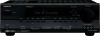
Owner Manual
Page 1
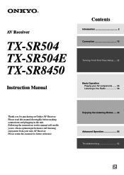
Following the instructions in the unit. AV Receiver TX-SR504 TX-SR504E TX-SR8450 Instruction Manual Contents Introduction 2 Connection 16 Turning On & First Time Setup..... 32 Basic Operation Playing your AV components ....... 36 Listening to obtain optimum performance and listening enjoyment from your new AV Receiver. Enjoying the Listening Modes ..... 48 Advanced Operation 54 Troubleshooting 62 En...
Following the instructions in the unit. AV Receiver TX-SR504 TX-SR504E TX-SR8450 Instruction Manual Contents Introduction 2 Connection 16 Turning On & First Time Setup..... 32 Basic Operation Playing your AV components ....... 36 Listening to obtain optimum performance and listening enjoyment from your new AV Receiver. Enjoying the Listening Modes ..... 48 Advanced Operation 54 Troubleshooting 62 En...
Owner Manual
Page 3
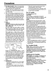
... this unit for personal use only, recording copyrighted material is illegal without the permission of the following measures: • Reorient or relocate the receiving antenna. • Increase the separation between 220 and 240 volts, set to Part 15 of mild detergent and water. Don't use . ...reception, which the receiver is no guarantee that to which can radiate radio frequency energy and, if not installed and used in your area. These limits are wet or damp. NOTE: This equipment has been tested and found to correct the interference by your Onkyo dealer. 3. nician...
... this unit for personal use only, recording copyrighted material is illegal without the permission of the following measures: • Reorient or relocate the receiving antenna. • Increase the separation between 220 and 240 volts, set to Part 15 of mild detergent and water. Don't use . ...reception, which the receiver is no guarantee that to which can radiate radio frequency energy and, if not installed and used in your area. These limits are wet or damp. NOTE: This equipment has been tested and found to correct the interference by your Onkyo dealer. 3. nician...

Owner Manual
Page 4
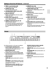
...Left Surround Back Right Surround Back Right Zone 2 Right Zone 2 Right Supplied Accessories Make sure you have the same ampere rating as that the ONKYO product described in this adapter if your AC outlet does not match with the following accessories: Remote controller and two batteries (AA/R6) Indoor... or coloured red. If the fuse needs to be connected to country.) 1 2 3 Speaker Cable Speaker cable labels * In catalogs and on the AV receiver's power cord. (Adapter varies from country to the terminal which is fitted with the letter N or coloured black. If the power cord's plug ...
...Left Surround Back Right Surround Back Right Zone 2 Right Zone 2 Right Supplied Accessories Make sure you have the same ampere rating as that the ONKYO product described in this adapter if your AC outlet does not match with the following accessories: Remote controller and two batteries (AA/R6) Indoor... or coloured red. If the fuse needs to be connected to country.) 1 2 3 Speaker Cable Speaker cable labels * In catalogs and on the AV receiver's power cord. (Adapter varies from country to the terminal which is fitted with the letter N or coloured black. If the power cord's plug ...

Owner Manual
Page 6
AV receiver SPEAKERS A B Remote controller or Speaker set A On Off Speaker set A is reduced to 5.1-channel playback. They should be used in another room and offers 2-channel stereo playback. *Only analog input sources are output by installing the subwoofer in a front corner, or at one... speaker set B can use two sets of speakers with the AV receiver: speaker set A and speaker set B is on , speaker set B On Off On Off Indicator AB A B Output Set A: 5.1 channels Set B: 2 channels Set A: 7.1 channels Set B: 2 channels No sound Speaker Set A: Main Room Front left and right speakers...
AV receiver SPEAKERS A B Remote controller or Speaker set A On Off Speaker set A is reduced to 5.1-channel playback. They should be used in another room and offers 2-channel stereo playback. *Only analog input sources are output by installing the subwoofer in a front corner, or at one... speaker set B can use two sets of speakers with the AV receiver: speaker set A and speaker set B is on , speaker set B On Off On Off Indicator AB A B Output Set A: 5.1 channels Set B: 2 channels Set A: 7.1 channels Set B: 2 channels No sound Speaker Set A: Main Room Front left and right speakers...

Owner Manual
Page 7
...CDR, MiniDisc, or DAT Recorder 30 Connecting the Power Cord of Another Component 30 Connecting Onkyo Components..........31 Connecting the Power Cord 31 Turning On & First Time Setup Turning On the AV Receiver 32 First Time Setup 33 Assigning Digital Inputs to Input Sources ....33 Changing the Input ... Input 37 Displaying Source Information 37 Listening to the Radio 38 Listening to AM/FM stations 38 Presetting AM/FM Stations and XM Channels 39 Listening to XM Satellite Radio® (North American Models Only 42 Common Functions 46 Setting the Display Brightness 46 Adjusting the ...
...CDR, MiniDisc, or DAT Recorder 30 Connecting the Power Cord of Another Component 30 Connecting Onkyo Components..........31 Connecting the Power Cord 31 Turning On & First Time Setup Turning On the AV Receiver 32 First Time Setup 33 Assigning Digital Inputs to Input Sources ....33 Changing the Input ... Input 37 Displaying Source Information 37 Listening to the Radio 38 Listening to AM/FM stations 38 Presetting AM/FM Stations and XM Channels 39 Listening to XM Satellite Radio® (North American Models Only 42 Common Functions 46 Setting the Display Brightness 46 Adjusting the ...

Owner Manual
Page 8
... presets (see the pages in parentheses. B STANDBY indicator (32) Lights up when the AV receiver is being received from the remote controller. C Remote-control sensor (11) Receives control signals from the remote controller. The [MULTI CH] button selects the multichannel DVD input. With... button is selected, the TUNING [ ] [ ] buttons are used for connecting a standard pair of the AV receiver to MIN, 1 through 79, or MAX. Getting to Know the AV Receiver Front Panel North American Model 12 3 45 6 7 STANDBY/ON STANDBY PHONES TUNING PRESET MULTI CH DVD VIDEO ...
... presets (see the pages in parentheses. B STANDBY indicator (32) Lights up when the AV receiver is being received from the remote controller. C Remote-control sensor (11) Receives control signals from the remote controller. The [MULTI CH] button selects the multichannel DVD input. With... button is selected, the TUNING [ ] [ ] buttons are used for connecting a standard pair of the AV receiver to MIN, 1 through 79, or MAX. Getting to Know the AV Receiver Front Panel North American Model 12 3 45 6 7 STANDBY/ON STANDBY PHONES TUNING PRESET MULTI CH DVD VIDEO ...
Owner Manual
Page 9
... when the Sleep function has been set A is on . RDS (European models only) (40): Lights up when presetting radio stations. Getting to Know the AV Receiver-Continued J TONE, [-], and [+] buttons (46) Used to a radio station that supports RDS (Radio Data System). M DISPLAY button (37) Displays various information about the selected input...) Selects the Stereo listening mode. Selects the Pure Audio listening mode. See "Using RDS (European Models Only)" on . 2 MUTING indicator (46) Flashes while the AV receiver is on page 40.
... when the Sleep function has been set A is on . RDS (European models only) (40): Lights up when presetting radio stations. Getting to Know the AV Receiver-Continued J TONE, [-], and [+] buttons (46) Used to a radio station that supports RDS (Radio Data System). M DISPLAY button (37) Displays various information about the selected input...) Selects the Stereo listening mode. Selects the Pure Audio listening mode. See "Using RDS (European Models Only)" on . 2 MUTING indicator (46) Flashes while the AV receiver is on page 40.
Owner Manual
Page 10
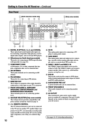
...A L CENTER SPEAKER R PRE OUT SUB WOOFER FRONT SPEAKERS B L R VOLTAGE SELECTOR AC OUTLET AC 120V 60Hz SWITCHED TOTAL 120W 1A MAX. 120V AV RECEIVER 220-240V 9 JK L M A DIGITAL IN OPTICAL 1, 2, 3, and COAXIAL These optical and coaxial digital audio inputs are for connecting components with an analog...be connected here. O FRONT SPEAKERS B These push terminals are for connecting an FM antenna. The type of outlet depends on another -capable Onkyo com- F MONITOR OUT The S-Video or composite video output should be used to connect a DVD player with optical or coaxial digital audio ...
...A L CENTER SPEAKER R PRE OUT SUB WOOFER FRONT SPEAKERS B L R VOLTAGE SELECTOR AC OUTLET AC 120V 60Hz SWITCHED TOTAL 120W 1A MAX. 120V AV RECEIVER 220-240V 9 JK L M A DIGITAL IN OPTICAL 1, 2, 3, and COAXIAL These optical and coaxial digital audio inputs are for connecting components with an analog...be connected here. O FRONT SPEAKERS B These push terminals are for connecting an FM antenna. The type of outlet depends on another -capable Onkyo com- F MONITOR OUT The S-Video or composite video output should be used to connect a DVD player with optical or coaxial digital audio ...
Owner Manual
Page 11
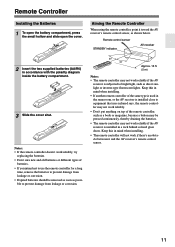
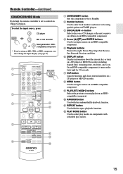
.... • If another remote controller of the same type is used in a rack behind colored glass doors. Remote control sensor STANDBY indicator AV receiver 2 Insert the two supplied batteries (AA/R6) in mind when installing. • The remote controller will not work if there's an obstacle ...between it toward the AV receiver's remote control sensor, as shown below. Approx. 16 ft. (5 m) Notes: • The remote controller may not work reliably. • Don't ...
.... • If another remote controller of the same type is used in a rack behind colored glass doors. Remote control sensor STANDBY indicator AV receiver 2 Insert the two supplied batteries (AA/R6) in mind when installing. • The remote controller will not work if there's an obstacle ...between it toward the AV receiver's remote control sensor, as shown below. Approx. 16 ft. (5 m) Notes: • The remote controller may not work reliably. • Don't ...
Owner Manual
Page 12
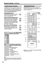
... SAT 2 Use the buttons supported by using the six REMOTE MODE buttons. ■ RECEIVER/TAPE Mode In RECEIVER/TAPE mode, you can control RECEIVER the AV receiver and an Onkyo cassette TAPE recorder connected via . 1 2 3 1 4 2 5 36 7 4 8 9 J ON/STANDBY REMOTE MODE RECEIVER DVD TAPE INPUT SELECTOR 1 2 3 V1 V2 V3 M D/CDR C D HDD .... ■ DVD and CD/MD/CDR/HDD Modes With these modes, you can control Onkyo components or components made by other components. 12 RECEIVER/TAPE Mode RECEIVER/TAPE mode is used when the TUNER or TAPE input is selected. LEVEL+ PLAY MODE ...
... SAT 2 Use the buttons supported by using the six REMOTE MODE buttons. ■ RECEIVER/TAPE Mode In RECEIVER/TAPE mode, you can control RECEIVER the AV receiver and an Onkyo cassette TAPE recorder connected via . 1 2 3 1 4 2 5 36 7 4 8 9 J ON/STANDBY REMOTE MODE RECEIVER DVD TAPE INPUT SELECTOR 1 2 3 V1 V2 V3 M D/CDR C D HDD .... ■ DVD and CD/MD/CDR/HDD Modes With these modes, you can control Onkyo components or components made by other components. 12 RECEIVER/TAPE Mode RECEIVER/TAPE mode is used when the TUNER or TAPE input is selected. LEVEL+ PLAY MODE ...

Owner Manual
Page 13
...a remote controller button is selected To select your Cassette deck as the input source, press: RECEIVER 8 TUNER 1 Number, D TUN, and ENT buttons (39, 43) Used to select AM and FM radio stations and XM radio channels directly. 2 CH +/- The Left and Right [ ]/[ ] buttons are used to adjust the... ENTER buttons For AM and FM, the Up and Down [ ]/[ ] buttons are used to select channels, and the [ENTER] button is selected To select the Tuner (AM/FM/XM) as the input source, press: RECEIVER 7 TAPE 4 Playback buttons On twin cassette decks, only deck B can be controlled. Q L NIGHT...
...a remote controller button is selected To select your Cassette deck as the input source, press: RECEIVER 8 TUNER 1 Number, D TUN, and ENT buttons (39, 43) Used to select AM and FM radio stations and XM radio channels directly. 2 CH +/- The Left and Right [ ]/[ ] buttons are used to adjust the... ENTER buttons For AM and FM, the Up and Down [ ]/[ ] buttons are used to select channels, and the [ENTER] button is selected To select the Tuner (AM/FM/XM) as the input source, press: RECEIVER 7 TAPE 4 Playback buttons On twin cassette decks, only deck B can be controlled. Q L NIGHT...
Owner Manual
Page 14
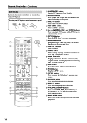
... NIGHT VCR DVD CINE FLTR HDD RC-647M DVD K L M N O P Q A ON/STANDBY button Sets the DVD player to control an Onkyo DVD player. P VCR, DVD, and HDD buttons Used to select VCR, HDD (hard disk drive), or DVD playback on components with the repeat ...playback functions. C DISC +/- To select your DVD player as the input source, press: RECEIVER 6 DVD or 5 MULTI CH 1 2 3 4 5 6 7 8 9 J ON/STANDBY REMOTE MODE RECEIVER DVD TAPE INPUT SELECTOR 1 2 3 V1 V2 V3 M D/CDR C D HDD 4 5 6 TV MULTI CH DVD 7 8 9 VCR TAPE ...
... NIGHT VCR DVD CINE FLTR HDD RC-647M DVD K L M N O P Q A ON/STANDBY button Sets the DVD player to control an Onkyo DVD player. P VCR, DVD, and HDD buttons Used to select VCR, HDD (hard disk drive), or DVD playback on components with the repeat ...playback functions. C DISC +/- To select your DVD player as the input source, press: RECEIVER 6 DVD or 5 MULTI CH 1 2 3 4 5 6 7 8 9 J ON/STANDBY REMOTE MODE RECEIVER DVD TAPE INPUT SELECTOR 1 2 3 V1 V2 V3 M D/CDR C D HDD 4 5 6 TV MULTI CH DVD 7 8 9 VCR TAPE ...
Owner Manual
Page 15
... V2 * If you're using an MD, CDR, or HDD component, you must change the Input Display (see page 33). 1 2 3 4 E F ON/STANDBY REMOTE MODE RECEIVER DVD TAPE INPUT SELECTOR 1 2 3 V1 V2 V3 M D/CDR C D HDD 4 5 6 TV MULTI CH DVD 7 8 9 VCR TAPE TUNER 10 11 +10 0 C... D 12 CABLE CLR SAT D TUN --/--- D Arrow [ ]/[ ] and ENTER buttons Used to control an Onkyo CD player. On an HDD-compatible component, it turns on an HDD-compatible component. C DISC/ALBUM +/- E Playback buttons From left to On or Standby. G CLR...
... V2 * If you're using an MD, CDR, or HDD component, you must change the Input Display (see page 33). 1 2 3 4 E F ON/STANDBY REMOTE MODE RECEIVER DVD TAPE INPUT SELECTOR 1 2 3 V1 V2 V3 M D/CDR C D HDD 4 5 6 TV MULTI CH DVD 7 8 9 VCR TAPE TUNER 10 11 +10 0 C... D 12 CABLE CLR SAT D TUN --/--- D Arrow [ ]/[ ] and ENTER buttons Used to control an Onkyo CD player. On an HDD-compatible component, it turns on an HDD-compatible component. C DISC/ALBUM +/- E Playback buttons From left to On or Standby. G CLR...
Owner Manual
Page 16
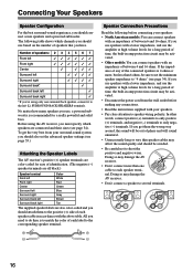
... levels for a long period of time, the built-in amp protection circuit may damage the AV receiver. • Don't connect a speaker to several terminals. 16 All you must specify which channels you use speakers with an impedance of each speaker cable in accordance with a lower impedance, and ...4 ohms or more than 6 ohms, be sure to set the advanced speaker settings (see page 55.) Attaching the Speaker Labels The AV receiver's positive (+) speaker terminals are color-coded for ease of identification. (The negative (-) speaker terminals are all black.) Speaker terminal Color...
... levels for a long period of time, the built-in amp protection circuit may damage the AV receiver. • Don't connect a speaker to several terminals. 16 All you must specify which channels you use speakers with an impedance of each speaker cable in accordance with a lower impedance, and ...4 ohms or more than 6 ohms, be sure to set the advanced speaker settings (see page 55.) Attaching the Speaker Labels The AV receiver's positive (+) speaker terminals are color-coded for ease of identification. (The negative (-) speaker terminals are all black.) Speaker terminal Color...

Owner Manual
Page 17
...CENTER SURR BACK R VIDEO 2 VIDEO 1 SUB WOOFER DVD SURROUND SPEAKERS FRONT SPEAKERS A L CENTER SPEAKER R PRE OUT SUB WOOFER FRONT SPEAKERS B L R AV RECEIVER AC OUTLET AC 120V 60Hz SWITCHED TOTAL 120W 1A MAX. If your powered subwoofer. Connecting Speaker Set B 1 Strip 3/8" (10 mm) of insulation from the ends...the input on , speaker set A is unpowered and you 're using an external amplifier, connect the SUBWOOFER PRE OUT to it to 5.1-channel playback. Note: Make sure the plugs are gripping the bare wires, not the insulation. 3/8" (10 mm) Note: While speaker set B is on...
...CENTER SURR BACK R VIDEO 2 VIDEO 1 SUB WOOFER DVD SURROUND SPEAKERS FRONT SPEAKERS A L CENTER SPEAKER R PRE OUT SUB WOOFER FRONT SPEAKERS B L R AV RECEIVER AC OUTLET AC 120V 60Hz SWITCHED TOTAL 120W 1A MAX. If your powered subwoofer. Connecting Speaker Set B 1 Strip 3/8" (10 mm) of insulation from the ends...the input on , speaker set A is unpowered and you 're using an external amplifier, connect the SUBWOOFER PRE OUT to it to 5.1-channel playback. Note: Make sure the plugs are gripping the bare wires, not the insulation. 3/8" (10 mm) Note: While speaker set B is on...

Owner Manual
Page 18
...FRONT SURROUND CENTER SURR BACK R VIDEO 2 VIDEO 1 SUB WOOFER DVD SURROUND SPEAKERS FRONT SPEAKERS A L CENTER SPEAKER R PRE OUT SUB WOOFER FRONT SPEAKERS B L R AV RECEIVER AC OUTLET AC 120V 60Hz SWITCHED TOTAL 120W 1A MAX. Keep the antenna as far away as shown. 2 Connect both wires of the FM antenna...This section explains how to connect the supplied indoor FM antenna and AM loop antenna, and how to tune into the jack. The AV receiver won't pick up any radio signals without any antenna connected, so you must connect the antenna to achieve the best possible reception. Insert ...
...FRONT SURROUND CENTER SURR BACK R VIDEO 2 VIDEO 1 SUB WOOFER DVD SURROUND SPEAKERS FRONT SPEAKERS A L CENTER SPEAKER R PRE OUT SUB WOOFER FRONT SPEAKERS B L R AV RECEIVER AC OUTLET AC 120V 60Hz SWITCHED TOTAL 120W 1A MAX. Keep the antenna as far away as shown. 2 Connect both wires of the FM antenna...This section explains how to connect the supplied indoor FM antenna and AM loop antenna, and how to tune into the jack. The AV receiver won't pick up any radio signals without any antenna connected, so you must connect the antenna to achieve the best possible reception. Insert ...

Owner Manual
Page 19
TV/FM antenna splitter To AV receiver To TV (or VCR) 19 Outdoor antenna AM loop antenna Insulated antenna cable Notes: • Outdoor FM antennas work best when installed horizontally outside , but ...
TV/FM antenna splitter To AV receiver To TV (or VCR) 19 Outdoor antenna AM loop antenna Insulated antenna cable Notes: • Outdoor FM antennas work best when installed horizontally outside , but ...

Owner Manual
Page 20
... video inputs and outputs. It's the most common connection format for optical. Note: The AV receiver does not support SCART connections. 20 Push plugs in all the way to connect right-channel audio inputs and outputs (typically labeled "R"). The audio quality is inserted and close when it's ...removed. Optical Digital Jacks The AV receiver's optical digital jacks have shutter-type covers that open when an optical...
... video inputs and outputs. It's the most common connection format for optical. Note: The AV receiver does not support SCART connections. 20 Push plugs in all the way to connect right-channel audio inputs and outputs (typically labeled "R"). The audio quality is inserted and close when it's ...removed. Optical Digital Jacks The AV receiver's optical digital jacks have shutter-type covers that open when an optical...
Owner Manual
Page 21
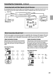
... Multichannel TV, projector, etc. OUT Input Cassette recorder, etc. Connecting Your Components-Continued Connecting Audio and Video Signals to the AV Receiver By connecting both the audio and video outputs of your DVD player and other components. Audio Signal Flow Chart CD player, etc.... For video components, such as a guide. Analog 21 The AV receiver supports several connection formats for hookup details) TV, projector, etc. The format you must make an audio connection and a video connection. Speakers...
... Multichannel TV, projector, etc. OUT Input Cassette recorder, etc. Connecting Your Components-Continued Connecting Audio and Video Signals to the AV Receiver By connecting both the audio and video outputs of your DVD player and other components. Audio Signal Flow Chart CD player, etc.... For video components, such as a guide. Analog 21 The AV receiver supports several connection formats for hookup details) TV, projector, etc. The format you must make an audio connection and a video connection. Speakers...

Owner Manual
Page 22
... ( A , B , or C ), and then make the connection. • With connection a , you can listen to TV programs through the AV receiver (see page 33) TV, projector, etc. Connecting Your Components-Continued Connecting a TV or Projector Step 1: Video Connection Choose a video connection that matches your ...! Step 2: Audio Connection Choose an audio connection that matches your VCR or cable or satellite receiver to the AV receiver and use a and b , or a and c .) Connection A B C a b c AV receiver COMPONENT VIDEO OUT MONITOR OUT S MONITOR OUT V VIDEO 2 IN L/R DIGITAL IN COAXIAL DIGITAL...
... ( A , B , or C ), and then make the connection. • With connection a , you can listen to TV programs through the AV receiver (see page 33) TV, projector, etc. Connecting Your Components-Continued Connecting a TV or Projector Step 1: Video Connection Choose a video connection that matches your ...! Step 2: Audio Connection Choose an audio connection that matches your VCR or cable or satellite receiver to the AV receiver and use a and b , or a and c .) Connection A B C a b c AV receiver COMPONENT VIDEO OUT MONITOR OUT S MONITOR OUT V VIDEO 2 IN L/R DIGITAL IN COAXIAL DIGITAL...


