Owner Manual
Page 2
... any kind into the apparatus, C. Servicing is required when the apparatus has been damaged in accordance with one wider than the other controls may be set 10 cm (4") away from the apparatus. 11. If the apparatus has been dropped or damaged in a fire or electric shock. When the apparatus exhibits a distinct...
... any kind into the apparatus, C. Servicing is required when the apparatus has been damaged in accordance with one wider than the other controls may be set 10 cm (4") away from the apparatus. 11. If the apparatus has been dropped or damaged in a fire or electric shock. When the apparatus exhibits a distinct...
Owner Manual
Page 5
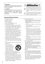
... Universal Port Option Series 46 Connecting Onkyo V Components 47 Connecting the Power Cord 47 Turning On & First Time Setup Turning On the AV receiver 48 Turning On and Standby 48 First...the Audio Settings 117 NET/USB NET/USB 120 About NET 120 Connecting the AV Receiver 120 Listening to Internet Radio 121 Playing Music Files on a Server 122 Network Settings 126 About...152 Using Normal Macros 153 Others Troubleshooting 154 Specifications (TX-NR3007 160 Specifications (TX-NR5007 161 Video Resolution Chart 162 * To reset the AV receiver to its factory defaults, turn it on and, while...
... Universal Port Option Series 46 Connecting Onkyo V Components 47 Connecting the Power Cord 47 Turning On & First Time Setup Turning On the AV receiver 48 Turning On and Standby 48 First...the Audio Settings 117 NET/USB NET/USB 120 About NET 120 Connecting the AV Receiver 120 Listening to Internet Radio 121 Playing Music Files on a Server 122 Network Settings 126 About...152 Using Normal Macros 153 Others Troubleshooting 154 Specifications (TX-NR3007 160 Specifications (TX-NR5007 161 Video Resolution Chart 162 * To reset the AV receiver to its factory defaults, turn it on and, while...
Owner Manual
Page 8
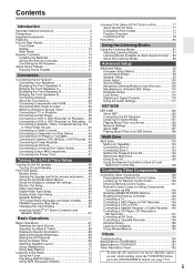
C STANDBY indicator (48) Lights when the AV receiver is in parentheses show where you can also be displayed as an absolute value. E ZONE 3 indicator (136) Lights when Zone 3 is being received from the remote controller. The transmitter transmits setting data to the remote controller. See "Volume Setup" ... Audio listening mode. H Display See "Display" on page 110. D ZONE 2 indicator (136) Lights when Zone 2 is used to set the AV receiver to On or Standby. F Input selector buttons (67) These buttons are not shown here for each item. Pressing this button again selects ...
C STANDBY indicator (48) Lights when the AV receiver is in parentheses show where you can also be displayed as an absolute value. E ZONE 3 indicator (136) Lights when Zone 3 is being received from the remote controller. The transmitter transmits setting data to the remote controller. See "Volume Setup" ... Audio listening mode. H Display See "Display" on page 110. D ZONE 2 indicator (136) Lights when Zone 2 is used to set the AV receiver to On or Standby. F Input selector buttons (67) These buttons are not shown here for each item. Pressing this button again selects ...
Owner Manual
Page 9
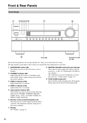
... used to tune the tuner, and the PRESET [F]/[S] buttons are used with video games. M TONE button (68, 137) Used to select and set the "Monitor Out" setting. Q DIMMER button (69) (North American models) This button is also used to select Zone 2. When the onscreen setup menus are used when ... N LEVEL button (137) Used to adjust the display brightness. See "Using RDS (European models)" on the connected TV. O MONITOR OUT button (49) Used to set items. The [ENTER] button is used to select the tone (bass and treble) for the main room, and the tone and balance for private listening...
... used to tune the tuner, and the PRESET [F]/[S] buttons are used with video games. M TONE button (68, 137) Used to select and set the "Monitor Out" setting. Q DIMMER button (69) (North American models) This button is also used to select Zone 2. When the onscreen setup menus are used when ... N LEVEL button (137) Used to adjust the display brightness. See "Using RDS (European models)" on the connected TV. O MONITOR OUT button (49) Used to set items. The [ENTER] button is used to select the tone (bass and treble) for the main room, and the tone and balance for private listening...

Owner Manual
Page 10
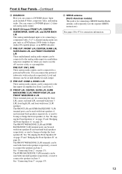
... Surround right SBL: Surround back left SB: Surround back SBR: Surround back right C Z2 indicator (136) Lights when Powered Zone 2 is selected. 10 G NETWORK indicator (121) Lights when the Net input selector is being used. X USB port (127) A USB mass storage device, such as a USB flash drive or... 137) Used to On or Standby. There are outputted for Zone 2 or Zone 3. [ DISPLAY button (68) This button is completely shutdown. When set the AV receiver to adjust the tone (bass and treble) for the main room and the volume, tone and balance for the current listening mode. Audyssey (61, 98...
... Surround right SBL: Surround back left SB: Surround back SBR: Surround back right C Z2 indicator (136) Lights when Powered Zone 2 is selected. 10 G NETWORK indicator (121) Lights when the Net input selector is being used. X USB port (127) A USB mass storage device, such as a USB flash drive or... 137) Used to On or Standby. There are outputted for Zone 2 or Zone 3. [ DISPLAY button (68) This button is completely shutdown. When set the AV receiver to adjust the tone (bass and treble) for the main room and the volume, tone and balance for the current listening mode. Audyssey (61, 98...

Owner Manual
Page 11
...2/3, or control it when it's out of headphones are for example, installed in a cabinet. P MUTING indicator (69) Flashes while the AV receiver is selected for connecting the component with optical digital audio outputs, such as UP-A1 Dock. O Volume level (67) Displays the volume ... Tuning mode is muted. TUNED (73): Lights when tuned to a stereo FM station. I SLEEP indicator (69) Lights when the Sleep function has been set to "Bi-Amp". Rear Panel (TX-NR5007) * North American models BCDE F G HI JK L M NO P Q R S T U V W X Y Z [ " # $ %* B UNIVERSAL PORT This port is selected...
...2/3, or control it when it's out of headphones are for example, installed in a cabinet. P MUTING indicator (69) Flashes while the AV receiver is selected for connecting the component with optical digital audio outputs, such as UP-A1 Dock. O Volume level (67) Displays the volume ... Tuning mode is muted. TUNED (73): Lights when tuned to a stereo FM station. I SLEEP indicator (69) Lights when the Sleep function has been set to "Bi-Amp". Rear Panel (TX-NR5007) * North American models BCDE F G HI JK L M NO P Q R S T U V W X Y Z [ " # $ %* B UNIVERSAL PORT This port is selected...
Owner Manual
Page 13
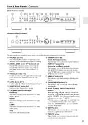
... L/R terminal posts can be connected to the line inputs on page 26. Front & Rear Panels-Continued Z DVD/BD IN Here you want to use the AV receiver solely as a DVD player, DVD-Audio or Super Audio CD-capable player, or an MPEG decoder. The FRONT WIDE/ZONE 2 L/R terminals can be used ... can be used with surround speakers respectively, or used to the analog audio input on page 131. The SURR BACK/ZONE 3 L/R terminals can be set individually for connection information. 13 See pages 18 to a powered subwoofer. You can be connected to bi-amp or bridge the front speakers A. PRE...
... L/R terminal posts can be connected to the line inputs on page 26. Front & Rear Panels-Continued Z DVD/BD IN Here you want to use the AV receiver solely as a DVD player, DVD-Audio or Super Audio CD-capable player, or an MPEG decoder. The FRONT WIDE/ZONE 2 L/R terminals can be used ... can be used with surround speakers respectively, or used to the analog audio input on page 131. The SURR BACK/ZONE 3 L/R terminals can be set individually for connection information. 13 See pages 18 to a powered subwoofer. You can be connected to bi-amp or bridge the front speakers A. PRE...
Owner Manual
Page 15
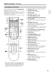
... VIDEO button (49, 53, 105) Used to change audio settings. P AUDIO button (117) Used to change video settings. See page 141 for more details. C ON button (48) Turns on the AV receiver. J DIMMER button (69) Adjusts the display brightness. E ...setting is used to select Receiver mode. B STANDBY button (48) Sets the AV receiver to the previous display when changing settings. L MUTING button (69) Mutes or unmutes the AV receiver. O RETURN button Returns to Standby. Remote Controller-Continued Controlling the AV Receiver To control the AV receiver, press the [RECEIVER...
... VIDEO button (49, 53, 105) Used to change audio settings. P AUDIO button (117) Used to change video settings. See page 141 for more details. C ON button (48) Turns on the AV receiver. J DIMMER button (69) Adjusts the display brightness. E ...setting is used to select Receiver mode. B STANDBY button (48) Sets the AV receiver to the previous display when changing settings. L MUTING button (69) Mutes or unmutes the AV receiver. O RETURN button Returns to Standby. Remote Controller-Continued Controlling the AV Receiver To control the AV receiver, press the [RECEIVER...

Owner Manual
Page 18
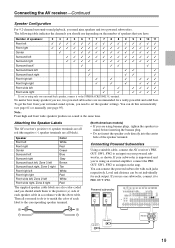
..., as required. Speakers B Subwoofer used with Speakers A and Speakers B. Connecting the AV receiver Connecting Your Speakers About Speakers A and Speakers B Speakers A and Speakers B allows you can configure the AV receiver to 26 for more information. Only one configuration can be bi-amped or bridged at... listening with a pair of highpower stereo speakers, the subwoofer is used , the AV receiver can only be wired normally. For example, if front Speakers A are configured by using the "Speaker Settings" on page 57 and "Speaker Setup" on the remote controller. SW1 SW2 SW1...
..., as required. Speakers B Subwoofer used with Speakers A and Speakers B. Connecting the AV receiver Connecting Your Speakers About Speakers A and Speakers B Speakers A and Speakers B allows you can configure the AV receiver to 26 for more information. Only one configuration can be bi-amped or bridged at... listening with a pair of highpower stereo speakers, the subwoofer is used , the AV receiver can only be wired normally. For example, if front Speakers A are configured by using the "Speaker Settings" on page 57 and "Speaker Setup" on the remote controller. SW1 SW2 SW1...
Owner Manual
Page 19
...you're using an external amplifier, connect the PRE OUT: SW1, SW2 to an input on the amp. Attaching the Speaker Labels The AV receiver's positive (+) speaker terminals are all red (the negative (-) speaker terminals are using only one subwoofer, connect it to the SURR BACK.../ZONE 3 L terminal. Connecting the AV receiver-Continued Speaker Configuration For 9.2-channel surround-sound playback, you need to set individually for a really powerful and solid bass. Connecting Powered Subwoofers Using a suitable cable, connect the AV receiver's PRE OUT: SW1, SW2 to an input on ...
...you're using an external amplifier, connect the PRE OUT: SW1, SW2 to an input on the amp. Attaching the Speaker Labels The AV receiver's positive (+) speaker terminals are all red (the negative (-) speaker terminals are using only one subwoofer, connect it to the SURR BACK.../ZONE 3 L terminal. Connecting the AV receiver-Continued Speaker Configuration For 9.2-channel surround-sound playback, you need to set individually for a really powerful and solid bass. Connecting Powered Subwoofers Using a suitable cable, connect the AV receiver's PRE OUT: SW1, SW2 to an input on ...
Owner Manual
Page 20
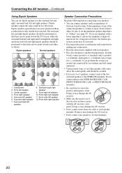
... their arrows point toward each of the wire does not have an arrow printed on them to indicate how they should be sure to set the minimum speaker impedance to the SURR L/R terminals. Dipole speakers typically have contact with an impedance of between 4 and 16 ohms. ... FRONT WIDE/ZONE 2 L/R, or FRONT HIGH L/R terminals. • Be careful not to each speaker terminal. Surround back right speaker 9. Doing so may damage the AV receiver. • Don't connect more , but less than one speaker to negative (-) terminals. In other , as shown. Do not connect them the wrong way around,...
... their arrows point toward each of the wire does not have an arrow printed on them to indicate how they should be sure to set the minimum speaker impedance to the SURR L/R terminals. Dipole speakers typically have contact with an impedance of between 4 and 16 ohms. ... FRONT WIDE/ZONE 2 L/R, or FRONT HIGH L/R terminals. • Be careful not to each speaker terminal. Surround back right speaker 9. Doing so may damage the AV receiver. • Don't connect more , but less than one speaker to negative (-) terminals. In other , as shown. Do not connect them the wrong way around,...
Owner Manual
Page 22
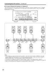
...Speakers B configuration, front high speakers cannnot be connected to each pair of the spakers you want to use with Speakers A or Speakers B. Connecting the AV receiver-Continued ■ 7.2-channel Playback with Speakers A or Speakers B The following illustration shows which of terminals for up to 7.2-channel playback with the Speakers ...A or Speakers B configuration (see page 96). • When you 're using the "Speaker Settings" on page 57 and "Speaker Setup" on page 95. • You can choose which speaker should be used. 22
...Speakers B configuration, front high speakers cannnot be connected to each pair of the spakers you want to use with Speakers A or Speakers B. Connecting the AV receiver-Continued ■ 7.2-channel Playback with Speakers A or Speakers B The following illustration shows which of terminals for up to 7.2-channel playback with the Speakers ...A or Speakers B configuration (see page 96). • When you 're using the "Speaker Settings" on page 57 and "Speaker Setup" on page 95. • You can choose which speaker should be used. 22
Owner Manual
Page 23
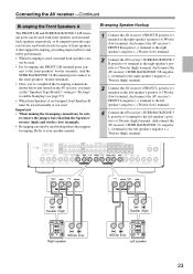
... BACK/ZONE 3 R negative (-) terminal to the right speaker's negative (-) Tweeter (high) terminal. 3 Connect the AV receiver's FRONT L positive (+) terminal to enable biamping (see page 57). • When front Speakers A are biamped, front Speakers B must set the "Speakers Type(FrontA)" setting to "Bi-Amp" to the left speaker's negative (-) Tweeter (high) terminal. And the SURR...
... BACK/ZONE 3 R negative (-) terminal to the right speaker's negative (-) Tweeter (high) terminal. 3 Connect the AV receiver's FRONT L positive (+) terminal to enable biamping (see page 57). • When front Speakers A are biamped, front Speakers B must set the "Speakers Type(FrontA)" setting to "Bi-Amp" to the left speaker's negative (-) Tweeter (high) terminal. And the SURR...
Owner Manual
Page 24
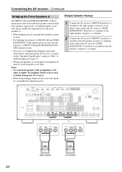
... completed the bridging connections shown below and turned on the AV receiver, you must set the "Speakers Type(FrontA)" setting to "BTL" to the left speaker's positive (+) terminal. And connect the AV receiver's SURR BACK/ZONE 3 R positive (+) terminal to the right speaker's negative (-) terminal. 2 Connect the AV receiver's FRONT L positive (+) terminal to the right speaker's positive (+) terminal. And...
... completed the bridging connections shown below and turned on the AV receiver, you must set the "Speakers Type(FrontA)" setting to "BTL" to the left speaker's positive (+) terminal. And connect the AV receiver's SURR BACK/ZONE 3 R positive (+) terminal to the right speaker's negative (-) terminal. 2 Connect the AV receiver's FRONT L positive (+) terminal to the right speaker's positive (+) terminal. And...

Owner Manual
Page 25
...the front speakers' tweeter terminals. • Once you've completed the bi-amping connections shown below and turned on the AV receiver, you must set the "Speakers Type(FrontB)" setting to "Bi-Amp" to enable biamping (see page 57). • When front Speakers B are biamped, front Speakers ... bass and treble performance. • When bi-amping is used . • For bi-amping, the FRONT WIDE/ZONE 2 L/R ter- And connect the AV receiver's SURR BACK/ZONE 3 L negative (-) terminal to the left speaker's positive (+) Tweeter (high) terminal. Refer to the right speaker's positive (+) Woofer (low...
...the front speakers' tweeter terminals. • Once you've completed the bi-amping connections shown below and turned on the AV receiver, you must set the "Speakers Type(FrontB)" setting to "Bi-Amp" to enable biamping (see page 57). • When front Speakers B are biamped, front Speakers ... bass and treble performance. • When bi-amping is used . • For bi-amping, the FRONT WIDE/ZONE 2 L/R ter- And connect the AV receiver's SURR BACK/ZONE 3 L negative (-) terminal to the left speaker's positive (+) Tweeter (high) terminal. Refer to the right speaker's positive (+) Woofer (low...
Owner Manual
Page 26
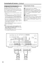
...terminal to enable bridging (see page 57). • When front Speakers B are bridged, front Speakers A must be wired normally. Connecting the AV receiver-Continued Bridging the Front Speakers B The FRONT WIDE/ZONE 2 L/R and SURR BACK/ZONE 3 L/R terminal posts can handle the additional power. Notes.../ZONE 3 L/R terminals are not. • Once you've completed the bridging connections shown below and turned on the AV receiver, you must set the "Speakers Type(FrontB)" setting to "BTL" to the left speaker's positive (+) terminal. Right speaker Left speaker 26 Failure to the right speaker's ...
...terminal to enable bridging (see page 57). • When front Speakers B are bridged, front Speakers A must be wired normally. Connecting the AV receiver-Continued Bridging the Front Speakers B The FRONT WIDE/ZONE 2 L/R and SURR BACK/ZONE 3 L/R terminal posts can handle the additional power. Notes.../ZONE 3 L/R terminals are not. • Once you've completed the bridging connections shown below and turned on the AV receiver, you must set the "Speakers Type(FrontB)" setting to "BTL" to the left speaker's positive (+) terminal. Right speaker Left speaker 26 Failure to the right speaker's ...

Owner Manual
Page 30
...over HDMI and is based on the following number to meet the increased demands of the system control function found on Onkyo components. The AV receiver's HDMI interface is part of the HDMI standard. Until now, several separate video and audio cables have been required ... Content Protection)*2, so only HDCP-compatible components can be guaranteed. • Set "HDMI Control (RIHD)" to the AV receiver via HDMI. • When the -compatible component more than the above audio formats. ■ Onkyo for System Control , which allows system control over HDMI, is the name...
...over HDMI and is based on the following number to meet the increased demands of the system control function found on Onkyo components. The AV receiver's HDMI interface is part of the HDMI standard. Until now, several separate video and audio cables have been required ... Content Protection)*2, so only HDCP-compatible components can be guaranteed. • Set "HDMI Control (RIHD)" to the AV receiver via HDMI. • When the -compatible component more than the above audio formats. ■ Onkyo for System Control , which allows system control over HDMI, is the name...
Owner Manual
Page 31
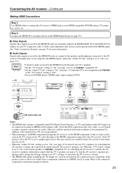
...IN TV DVD/BD player HD camcorder, etc Notes: • The HDMI video stream is set to the AV receiver. To stop the AV receiver's speakers pro- When the "TV Control" setting is set the HDMI component so that DVI connections only carry video, so you'll need to hear ... page 114) for an -compatible TV. • Set the "Audio TV Out" setting to "On" (see page 113) to the AV receiver). In addition, video signals from a PC are muted. ducing sound, change the settings, change your TV's settings, or turn down the AV receiver's volume. • The HDMI audio signal (sampling rate...
...IN TV DVD/BD player HD camcorder, etc Notes: • The HDMI video stream is set to the AV receiver. To stop the AV receiver's speakers pro- When the "TV Control" setting is set the HDMI component so that DVI connections only carry video, so you'll need to hear ... page 114) for an -compatible TV. • Set the "Audio TV Out" setting to "On" (see page 113) to the AV receiver). In addition, video signals from a PC are muted. ducing sound, change the settings, change your TV's settings, or turn down the AV receiver's volume. • The HDMI audio signal (sampling rate...
Owner Manual
Page 32
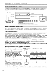
...video performance, THX recommends that for the HDMI output. Use the "HDMI Main" or "HDMI Sub" setting if you connect the AV Composite S-Video Component IN HDMI receiver's HDMI OUT MAIN or HDMI OUT SUB, respectively, to component video output). Release both buttons. The format... the buttons. ■ "Monitor Out" Setting Set to "HDMI Main" or "HDMI Sub" With the "Monitor Out" setting set to "Analog" (see page 21 for connection information) Which Connections Should I Use? DVD/BD player, etc. Connecting the AV receiver-Continued Connecting Both Audio & Video By connecting...
...video performance, THX recommends that for the HDMI output. Use the "HDMI Main" or "HDMI Sub" setting if you connect the AV Composite S-Video Component IN HDMI receiver's HDMI OUT MAIN or HDMI OUT SUB, respectively, to component video output). Release both buttons. The format... the buttons. ■ "Monitor Out" Setting Set to "HDMI Main" or "HDMI Sub" With the "Monitor Out" setting set to "Analog" (see page 21 for connection information) Which Connections Should I Use? DVD/BD player, etc. Connecting the AV receiver-Continued Connecting Both Audio & Video By connecting...
Owner Manual
Page 33
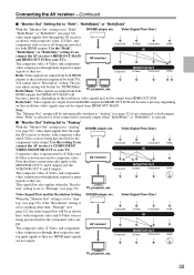
... resolution, video signals may not be automatically switched to composite video. Use this setting if you connect the AV receiver's HDMI OUT MAIN and HDMI OUT SUB to your TV. AV receiver Composite MONITOR OUT S-Video Component HDMI The composite video, S-Video, and component ...Analog" (see page 52). Video Signal Flow Chart When the "Monitor Out" setting is set to both HDMI outputs. AV receiver The composite video, S-Video, and component video outputs pass through the AV receiver as they are . HDMI input signals Composite MONITOR OUT S-Video Component HDMI are...
... resolution, video signals may not be automatically switched to composite video. Use this setting if you connect the AV receiver's HDMI OUT MAIN and HDMI OUT SUB to your TV. AV receiver Composite MONITOR OUT S-Video Component HDMI The composite video, S-Video, and component ...Analog" (see page 52). Video Signal Flow Chart When the "Monitor Out" setting is set to both HDMI outputs. AV receiver The composite video, S-Video, and component video outputs pass through the AV receiver as they are . HDMI input signals Composite MONITOR OUT S-Video Component HDMI are...


