Owner Manual
Page 3
... set to disconnect this Unit with the instructions, may damage the finish or remove the panel lettering. 4. Make sure that to which can radiate radio frequency energy and, if not installed and used to the correct voltage for an extended period, remove the power cord from country to operate the equipment. Pressing the [ON/STANDBY] button to provide reasonable protection...
... set to disconnect this Unit with the instructions, may damage the finish or remove the panel lettering. 4. Make sure that to which can radiate radio frequency energy and, if not installed and used to the correct voltage for an extended period, remove the power cord from country to operate the equipment. Pressing the [ON/STANDBY] button to provide reasonable protection...
Owner Manual
Page 4
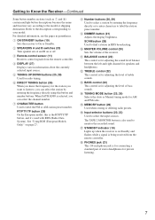
...Receiver 19 Turning On and Standby 19 Changing the Input Display 19 Enjoying Audio Sources 20 Muting the receiver (remote controller only) ........ 21 Using Headphones 21 Setting the Display Brightness 21 Using the Sleep Timer (remote controller only) ... 21 Using the Tone and Balance Controls 22 Recording 23 Recording the Input Source 23 Listening to the Radio 25 AM Frequency Step Setup (not North America and Europe 25 Listening to Know the Receiver 6 Front Panel 6 Rear Panel 8 Display 9 Remote Controller 10 Using the Remote Controller 11 Connections Connecting Your Speakers...
...Receiver 19 Turning On and Standby 19 Changing the Input Display 19 Enjoying Audio Sources 20 Muting the receiver (remote controller only) ........ 21 Using Headphones 21 Setting the Display Brightness 21 Using the Sleep Timer (remote controller only) ... 21 Using the Tone and Balance Controls 22 Recording 23 Recording the Input Source 23 Listening to the Radio 25 AM Frequency Step Setup (not North America and Europe 25 Listening to Know the Receiver 6 Front Panel 6 Rear Panel 8 Display 9 Remote Controller 10 Using the Remote Controller 11 Connections Connecting Your Speakers...
Owner Manual
Page 7
...inch phone jack is also used with RDS (Radio Data System). The TAPE 2 MONITOR button is for speakers and headphones. B SPEAKERS A and B switches (20) Turn speaker sets A and B on page 27. J MASTER VOLUME control (20) Sets the volume of stereo headphones for the station you want to listen to, you can select the station by entering the frequency directly or to enter characters to select a station by entering the frequency directly using this is for adjusting the level of treble sounds. C Remote-control sensor (11) Receives control signals from the remote controller...
...inch phone jack is also used with RDS (Radio Data System). The TAPE 2 MONITOR button is for speakers and headphones. B SPEAKERS A and B switches (20) Turn speaker sets A and B on page 27. J MASTER VOLUME control (20) Sets the volume of stereo headphones for the station you want to listen to, you can select the station by entering the frequency directly or to enter characters to select a station by entering the frequency directly using this is for adjusting the level of treble sounds. C Remote-control sensor (11) Receives control signals from the remote controller...
Owner Manual
Page 8
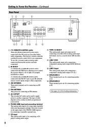
... OUT jack to pass IR (infrared) remote control signals along to other Onkyo audio components. Getting to Know the Receiver-Continued Rear Panel 12 3 4 5 67 8 9J KL A REMOTE CONTROL jacks These (Remote Interactive) jacks can be connected to the IR IN jack, allowing you to control the receiver when it's out of your components. The type of the PHONO (MM) inputs is for connecting a CD player's analog audio output. 8 H TAPE 1/2 IN/OUT This analog audio input and output are for connecting a turntable with an analog audio input and output...
... OUT jack to pass IR (infrared) remote control signals along to other Onkyo audio components. Getting to Know the Receiver-Continued Rear Panel 12 3 4 5 67 8 9J KL A REMOTE CONTROL jacks These (Remote Interactive) jacks can be connected to the IR IN jack, allowing you to control the receiver when it's out of your components. The type of the PHONO (MM) inputs is for connecting a CD player's analog audio output. 8 H TAPE 1/2 IN/OUT This analog audio input and output are for connecting a turntable with an analog audio input and output...

Owner Manual
Page 9
... function has been set A is on . 2 MUTING indicator Flashes while the receiver is muted. 3 Radio indicators TUNED: Lights up when tuned to a radio station. RDS (European models only): Lights up when presetting radio stations. Getting to Know the Receiver-Continued Display 12 3 4 5 For detailed information, see the pages in parentheses. 1 A and B speaker indicators Indicator A lights up when speaker set . 5 Message area Displays various information about the selected input source. 9 AUTO: For AM and FM radio, lights...
... function has been set A is on . 2 MUTING indicator Flashes while the receiver is muted. 3 Radio indicators TUNED: Lights up when tuned to a radio station. RDS (European models only): Lights up when presetting radio stations. Getting to Know the Receiver-Continued Display 12 3 4 5 For detailed information, see the pages in parentheses. 1 A and B speaker indicators Indicator A lights up when speaker set . 5 Message area Displays various information about the selected input source. 9 AUTO: For AM and FM radio, lights...

Owner Manual
Page 10
... radio stations and satellite radio channels directly. REPEAT: Used with no label does not work as number button for the station you want to listen to, you can be changed to select radio presets. I TUNING [ ]/[ ] buttons (25) When AM or FM is selected, you can select the station by entering the frequency directly using this time, the buttons can select the channel number. C INPUT SELECTOR buttons (20) and number buttons (26) When any of these buttons work for radio tuning. G DIMMER button (21) Adjusts the display...
... radio stations and satellite radio channels directly. REPEAT: Used with no label does not work as number button for the station you want to listen to, you can be changed to select radio presets. I TUNING [ ]/[ ] buttons (25) When AM or FM is selected, you can select the station by entering the frequency directly using this time, the buttons can select the channel number. C INPUT SELECTOR buttons (20) and number buttons (26) When any of these buttons work for radio tuning. G DIMMER button (21) Adjusts the display...
Owner Manual
Page 12
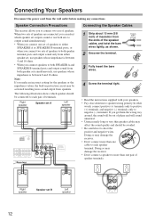
...; When you connect speakers to both SPEAKER A and SPEAKER B terminal posts and output sound from both speaker sets simultaneously, use speakers whose impedance is between 8 and 16 ohms. Note: If you make an incorrect setting for the speakers or the impedance values, the built-in no sound output from the ends of speakers. Right speaker Speaker set B Left speaker 12 Doing so may be avoided. • Be careful not to speaker wiring polarity. Doing...
...; When you connect speakers to both SPEAKER A and SPEAKER B terminal posts and output sound from both speaker sets simultaneously, use speakers whose impedance is between 8 and 16 ohms. Note: If you make an incorrect setting for the speakers or the impedance values, the built-in no sound output from the ends of speakers. Right speaker Speaker set B Left speaker 12 Doing so may be avoided. • Be careful not to speaker wiring polarity. Doing...
Owner Manual
Page 13
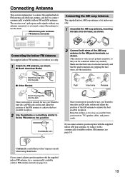
... connect the supplied indoor FM antenna and AM loop antenna, and how to use the tuner. The receiver won't pick up any radio signals without any antenna connected, so you 'll need to tune into position. Once your receiver is for use , you must connect the antenna to connect commercially available outdoor FM and AM antennas. If you 'll need to tune into an AM radio station and adjust...
... connect the supplied indoor FM antenna and AM loop antenna, and how to use the tuner. The receiver won't pick up any radio signals without any antenna connected, so you 'll need to tune into position. Once your receiver is for use , you must connect the antenna to connect commercially available outdoor FM and AM antennas. If you 'll need to tune into an AM radio station and adjust...
Owner Manual
Page 15
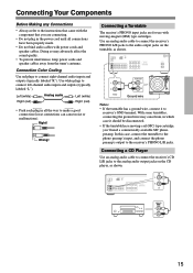
... tuner's antenna. Connecting a CD Player Use an analog audio cable to connect the receiver's CD L/R jacks to receiver's GND terminal. ANALOG OUT 15 Right! Use an analog audio cable to connect the receiver's PHONO L/R jacks to connect right-channel audio inputs and outputs (typically labeled "R"). Doing so may cause hum, in all connections have been properly made. • Do not bind audio cables with moving -coil (MC) type cartridge, you are for use with power cords and speaker cables. Connection Color Coding Use red plugs to the audio output jacks...
... tuner's antenna. Connecting a CD Player Use an analog audio cable to connect the receiver's CD L/R jacks to receiver's GND terminal. ANALOG OUT 15 Right! Use an analog audio cable to connect the receiver's PHONO L/R jacks to connect right-channel audio inputs and outputs (typically labeled "R"). Doing so may cause hum, in all connections have been properly made. • Do not bind audio cables with moving -coil (MC) type cartridge, you are for use with power cords and speaker cables. Connection Color Coding Use red plugs to the audio output jacks...
Owner Manual
Page 16
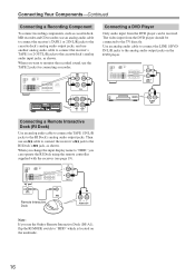
... Onkyo Remote Interactive Dock (DS-A1), flip the RI MODE switch to "HDD" which is located on the DVD player. L AUDIO OUT Note: If you use an cable to connect the receiver's jack to the RI Dock's jack, as shown. When you can be connected to the RI Dock's analog audio output jacks. Use an analog audio cable to connect the LINE 1/DVD IN L/R jacks to the analog audio output jacks on the underside. 16 L R AUDIO OUT TAPE 1 Remote Interactive Dock R ---- IN L R LINE 1 /DVD / REC PLAY (IN) (OUT) Connecting a Remote...
... Onkyo Remote Interactive Dock (DS-A1), flip the RI MODE switch to "HDD" which is located on the DVD player. L AUDIO OUT Note: If you use an cable to connect the receiver's jack to the RI Dock's jack, as shown. When you can be connected to the RI Dock's analog audio output jacks. Use an analog audio cable to connect the LINE 1/DVD IN L/R jacks to the analog audio output jacks on the underside. 16 L R AUDIO OUT TAPE 1 Remote Interactive Dock R ---- IN L R LINE 1 /DVD / REC PLAY (IN) (OUT) Connecting a Remote...
Owner Manual
Page 17
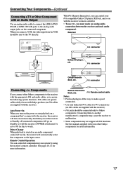
... set the receiver to work). Direct Change When playback is started on Standby as the input source. See pages 10-11 for connections (no cables are supplied with the appropriate and audio cables, you connect a VCR, the video input from the VCR should be connected only to make an analog audio connection between the receiver and each plug in your -compatible Onkyo CD player, RI Dock, and so on the connected component. With (Remote Interactive), you turn on the power...
... set the receiver to work). Direct Change When playback is started on Standby as the input source. See pages 10-11 for connections (no cables are supplied with the appropriate and audio cables, you connect a VCR, the video input from the VCR should be connected only to make an analog audio connection between the receiver and each plug in your -compatible Onkyo CD player, RI Dock, and so on the connected component. With (Remote Interactive), you turn on the power...
Owner Manual
Page 18
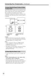
... which you connect to a suitable wall outlet. Connecting Your Components-Continued Connecting the Power Cords of Other Components The receiver has AC outlets on its rear panel that can then be left turned on so that they turn on and off as and when the receiver is a problem, plug the receiver into a different branch circuit. 18 These components can be connected directly to Standby. European models e.g. North American model Caution: •...
... which you connect to a suitable wall outlet. Connecting Your Components-Continued Connecting the Power Cords of Other Components The receiver has AC outlets on its rear panel that can then be left turned on so that they turn on and off as and when the receiver is a problem, plug the receiver into a different branch circuit. 18 These components can be connected directly to Standby. European models e.g. North American model Caution: •...
Owner Manual
Page 20
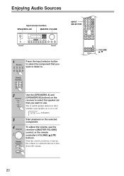
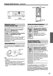
... adjust the volume, use . The A and B speaker indicators show whether each speaker set that you want to listen to. VOLUME / 20 Turn the control clockwise to turn up the volume or counterclockwise to turn down the volume. Remote controller 2 Receiver Use the [SPEAKERS A] and [SPEAKERS B] buttons on the receiver to select the speaker set is on the selected component. Enjoying Audio Sources Input selector buttons SPEAKERS A/B MASTER VOLUME INPUT SELECTOR 1 Receiver Press the input selector button to select the component that you want to use the receiver's [MASTER VOLUME...
... adjust the volume, use . The A and B speaker indicators show whether each speaker set that you want to listen to. VOLUME / 20 Turn the control clockwise to turn up the volume or counterclockwise to turn down the volume. Remote controller 2 Receiver Use the [SPEAKERS A] and [SPEAKERS B] buttons on the receiver to select the speaker set is on the selected component. Enjoying Audio Sources Input selector buttons SPEAKERS A/B MASTER VOLUME INPUT SELECTOR 1 Receiver Press the input selector button to select the component that you want to use the receiver's [MASTER VOLUME...
Owner Manual
Page 21
... the remote controller's VOLUME buttons are pressed or the receiver is muted. To turn down the volume before connecting your headphones. • Sound output from speakers, use the [DIMMER] button on the sound output from speakers is not turned off even if (when) the headphones plug is being displayed, you can set to Standby. SLEEP indicator To cancel the sleep timer, press the [SLEEP] button repeatedly until the SLEEP indicator disappears. The receiver is set the receiver...
... the remote controller's VOLUME buttons are pressed or the receiver is muted. To turn down the volume before connecting your headphones. • Sound output from speakers, use the [DIMMER] button on the sound output from speakers is not turned off even if (when) the headphones plug is being displayed, you can set to Standby. SLEEP indicator To cancel the sleep timer, press the [SLEEP] button repeatedly until the SLEEP indicator disappears. The receiver is set the receiver...

Owner Manual
Page 22
... The BALANCE control is used with any input source. Turn it up to make them louder. Adjusting the Treble The TREBLE control adjusts treble sounds. Turn it up to control the relative volume level of the left and right speaker systems or headphones. 22 Enjoying Audio Sources-Continued This section explains functions that can be used to make them louder. Turn it down to make them quieter. TREBLE BASS BALANCE Using the Tone and Balance Controls Adjusting the Bass The BASS control adjusts bass sounds.
... The BALANCE control is used with any input source. Turn it up to make them louder. Adjusting the Treble The TREBLE control adjusts treble sounds. Turn it up to control the relative volume level of the left and right speaker systems or headphones. 22 Enjoying Audio Sources-Continued This section explains functions that can be used to make them louder. Turn it down to make them quieter. TREBLE BASS BALANCE Using the Tone and Balance Controls Adjusting the Bass The BASS control adjusts bass sounds.

Owner Manual
Page 24
... displayed if a tuner is displayed, and release it when the sign changes to "T2 MONITOR ON." The signal flow in monitoring the recorded sound Receiver TAPE 2 T2 MONITOR OFF button Amplifier T2 MONITOR ON PLAY REC TAPE 2 Input source (CD, FM, etc.) The signal flow in the display. Pressing the TAPE 2 MONITOR button indicates a sign "T2 MONITOR OFF" on a recording component connected to compare the sounds by switching the output between the sound before recording Receiver TAPE...
... displayed if a tuner is displayed, and release it when the sign changes to "T2 MONITOR ON." The signal flow in monitoring the recorded sound Receiver TAPE 2 T2 MONITOR OFF button Amplifier T2 MONITOR ON PLAY REC TAPE 2 Input source (CD, FM, etc.) The signal flow in the display. Pressing the TAPE 2 MONITOR button indicates a sign "T2 MONITOR OFF" on a recording component connected to compare the sounds by switching the output between the sound before recording Receiver TAPE...

Owner Manual
Page 29
... a button is replaced with a frequency of 89.50 MHz has been stored in the display goes off and the cursor ( _ ) flashes. 3 Other than European model Continue pressing the [5MNO] button until "O" is not pressed within 16 seconds, the operation will be given the name "ONKYO." 1 Select the desired preset channel. (Refer to "Selecting Presets" on the front panel. Note: Press the [DISPLAY] button when...
... a button is replaced with a frequency of 89.50 MHz has been stored in the display goes off and the cursor ( _ ) flashes. 3 Other than European model Continue pressing the [5MNO] button until "O" is not pressed within 16 seconds, the operation will be given the name "ONKYO." 1 Select the desired preset channel. (Refer to "Selecting Presets" on the front panel. Note: Press the [DISPLAY] button when...
Owner Manual
Page 30
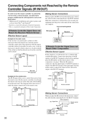
... IN Connecting block IR Receiver Receiver Remote controller In the cabinet Main room : Signal flow Example for the remote zone The IR IN input allows you to control the receiver from the remote zone with the remote controller will not be output to the IR OUT terminal. from the controller can be on the remote sensor of the cabinet so that the infrared rays from connecting block Mini plug cable Receiver If Remote Controller Signal...
... IN Connecting block IR Receiver Receiver Remote controller In the cabinet Main room : Signal flow Example for the remote zone The IR IN input allows you to control the receiver from the remote zone with the remote controller will not be output to the IR OUT terminal. from the controller can be on the remote sensor of the cabinet so that the infrared rays from connecting block Mini plug cable Receiver If Remote Controller Signal...
Owner Manual
Page 31
..., then plug it . • An audio cable may degrade the audio performance, so don't do it in contact with power cords, speaker cables, and so on the display and the receiver will delete your cables. Disconnect all speaker cables and input sources, and leave the receiver with its factory defaults, turn on the receiver • Make sure that resetting the receiver will enter Standby mode. Noise can cause interference. • Concrete walls weaken radio signals...
..., then plug it . • An audio cable may degrade the audio performance, so don't do it in contact with power cords, speaker cables, and so on the display and the receiver will delete your cables. Disconnect all speaker cables and input sources, and leave the receiver with its factory defaults, turn on the receiver • Make sure that resetting the receiver will enter Standby mode. Noise can cause interference. • Concrete walls weaken radio signals...
Owner Manual
Page 32
... The receiver uses a battery-less memory backup system in order to retain radio presets and other components • If you've connected an -capable Onkyo DS-A1 Remote Interactive Dock to the TAPE 1 jacks on the environment and will be recorded correctly. Relocate if necessary (page 11). Recording Can't record • On your recorder, make sure that the cable and analog audio cable are connected digitally (page...
... The receiver uses a battery-less memory backup system in order to retain radio presets and other components • If you've connected an -capable Onkyo DS-A1 Remote Interactive Dock to the TAPE 1 jacks on the environment and will be recorded correctly. Relocate if necessary (page 11). Recording Can't record • On your recorder, make sure that the cable and analog audio cable are connected digitally (page...


