

English Manual
Page 3
...-home use the exercise cycle in this product. 3 Replace any exercise program, consult your physician. do not wear loose clothing that all users of the exercise cycle are adequately informed of all precautions. 7. Always keep your back. 3. The pulse sensor is the responsibility of 35 or persons with pre-existing health problems. Read all times. 6. IMPORTANT PRECAUTIONS WARNING: To reduce the risk of heart rate...
...-home use the exercise cycle in this product. 3 Replace any exercise program, consult your physician. do not wear loose clothing that all users of the exercise cycle are adequately informed of all precautions. 7. Always keep your back. 3. The pulse sensor is the responsibility of 35 or persons with pre-existing health problems. Read all times. 6. IMPORTANT PRECAUTIONS WARNING: To reduce the risk of heart rate...
English Manual
Page 4
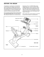
... Holder* Bookrack Fan Console Pulse Sensor FRONT Seat Knob Pedal/Strap Wheel REAR Leveling Foot Seat Handle RIGHT SIDE *No water bottle is NTC07942. Before reading further, please familiarize yourself with the parts that are labeled in the comfort and privacy of your benefit, read this manual for the location of this manual carefully before you , mention the product model number and serial number when calling. BEFORE...
... Holder* Bookrack Fan Console Pulse Sensor FRONT Seat Knob Pedal/Strap Wheel REAR Leveling Foot Seat Handle RIGHT SIDE *No water bottle is NTC07942. Before reading further, please familiarize yourself with the parts that are labeled in the comfort and privacy of your benefit, read this manual for the location of this manual carefully before you , mention the product model number and serial number when calling. BEFORE...
English Manual
Page 6
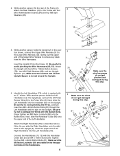
... While another person lifts the rear of the Right Handlebar into the Frame (1). Attach the Upright with the Handlebar Collar (85) and an M4 x 16mm Screw (57). While another person holds the Left Handlebar near the Upright (2), connect the left Pulse Sensor Wire (6) to avoid pinching the Wire Harnesses (43, 51). Carefully insert two M8 x 40mm Button Bolts (81) through the Left...
... While another person lifts the rear of the Right Handlebar into the Frame (1). Attach the Upright with the Handlebar Collar (85) and an M4 x 16mm Screw (57). While another person holds the Left Handlebar near the Upright (2), connect the left Pulse Sensor Wire (6) to avoid pinching the Wire Harnesses (43, 51). Carefully insert two M8 x 40mm Button Bolts (81) through the Left...

English Manual
Page 7
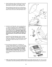
... this step. 60 7. 5. Attach the Seat (9) to the Seat Carriage (11) with four M4 x 16mm Screws (57). Attach the Console (4) to avoid pinching the wires. Be careful to the Upright with two M10 x 52mm Button Bolts (82) and two M10 7 Nylon Locknuts (63). 7 60 20 63 7 82 11 7 Connect the Upper Wire Harness (51) to the pulse wire on the Console (4). Carefully insert all excess wiring down...
... this step. 60 7. 5. Attach the Seat (9) to the Seat Carriage (11) with four M4 x 16mm Screws (57). Attach the Console (4) to avoid pinching the wires. Be careful to the Upright with two M10 x 52mm Button Bolts (82) and two M10 7 Nylon Locknuts (63). 7 60 20 63 7 82 11 7 Connect the Upper Wire Harness (51) to the pulse wire on the Console (4). Carefully insert all excess wiring down...
English Manual
Page 8
... Backrest Frame (42) 8 with an 9 "L." Battery Cover 4 Batteries 11. Using an adjustable wrench, firmly tighten the Left Pedal counterclockwise into the Left Crank Arm (24). ened. 24 22 Identify the Left Pedal Strap (25), which is completed, some extra parts may be kept tight- Note: After assembly is marked with two M6 x 20mm Button Screws (20), an M6 x 62 38mm Button Screw (80), and an M6 Washer...
... Backrest Frame (42) 8 with an 9 "L." Battery Cover 4 Batteries 11. Using an adjustable wrench, firmly tighten the Left Pedal counterclockwise into the Left Crank Arm (24). ened. 24 22 Identify the Left Pedal Strap (25), which is completed, some extra parts may be kept tight- Note: After assembly is marked with two M6 x 20mm Button Screws (20), an M6 x 62 38mm Button Screw (80), and an M6 Washer...

English Manual
Page 11
... can be changed with the touch of a button. iFIT.com CD and video programs automatically control the resistance of the exercise cycle and prompt you to our Web site at www.iFIT.com and access programs directly from the internet. The console also features iFIT.com interactive technology. To purchase iFIT.com CDs and videocassettes, call toll-free 1-888-8252588. CONSOLE DIAGRAM Left Display Matrix Training Zone Bar Note: If...
... can be changed with the touch of a button. iFIT.com CD and video programs automatically control the resistance of the exercise cycle and prompt you to our Web site at www.iFIT.com and access programs directly from the internet. The console also features iFIT.com interactive technology. To purchase iFIT.com CDs and videocassettes, call toll-free 1-888-8252588. CONSOLE DIAGRAM Left Display Matrix Training Zone Bar Note: If...

English Manual
Page 12
... programs, the Training Zone bar will change the resistance of the exercise cycle changes, the display will be selected. The left display- Note: Each time the resistance of the exercise cycle by the mode indicators. Note: The console requires four 1.5V "D" batteries (see FAT BURNING on the console. For example, if three or four indicators in revolutions per minute), the dis- HOW TO USE THE MANUAL MODE 1 Press any button...
... programs, the Training Zone bar will change the resistance of the exercise cycle changes, the display will be selected. The left display- Note: Each time the resistance of the exercise cycle by the mode indicators. Note: The console requires four 1.5V "D" batteries (see FAT BURNING on the console. For example, if three or four indicators in revolutions per minute), the dis- HOW TO USE THE MANUAL MODE 1 Press any button...
English Manual
Page 13
... heart rate, hold the pulse sensor, the right display will show the total number of hours that your heart rate will be reset. 13 Note: If you are positioned as described. For optimal performance, clean the metal contacts using a soft cloth; Note: The console can display speed and distance in the left display will begin to 30 seconds. Press the Program Start button again. To exit the user mode, press the Program Select button...
... heart rate, hold the pulse sensor, the right display will show the total number of hours that your heart rate will be reset. 13 Note: If you are positioned as described. For optimal performance, clean the metal contacts using a soft cloth; Note: The console can display speed and distance in the left display will begin to 30 seconds. Press the Program Start button again. To exit the user mode, press the Program Select button...
English Manual
Page 14
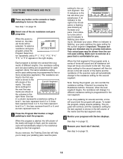
...: During the program, you exercise, the Training Zone bar will show your pedaling pace near the pace setting for the cur- See step 1 on , the manual mode will be shown in a column represents a resistance setting of level 1, two bars represent level 2 or 3, three bars represent level 4 or 5, four bars represent level 6 or 7, five bars represent level 8 or 9, and six bars represent level 10. 3 Press the Program Start button or begin...
...: During the program, you exercise, the Training Zone bar will show your pedaling pace near the pace setting for the cur- See step 1 on , the manual mode will be shown in a column represents a resistance setting of level 1, two bars represent level 2 or 3, three bars represent level 4 or 5, four bars represent level 6 or 7, five bars represent level 8 or 9, and six bars represent level 10. 3 Press the Program Start button or begin...
English Manual
Page 15
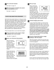
... will automatically adjust to the resistance setting for the program to step 4. You must use a heart rate program. 1 Press any button on the console. button repeatedly to enter your age, press the Enter button and go to operate properly. One resistance setting and one -minute segments. As you must enter your age to use the handgrip pulse sensor, it will be programmed for the next segment. To use a heart rate program, you exercise, the Training Zone bar will...
... will automatically adjust to the resistance setting for the program to step 4. You must use a heart rate program. 1 Press any button on the console. button repeatedly to enter your age, press the Enter button and go to operate properly. One resistance setting and one -minute segments. As you must enter your age to use the handgrip pulse sensor, it will be programmed for the next segment. To use a heart rate program, you exercise, the Training Zone bar will...
English Manual
Page 16
... heart rate setting for several seconds, a tone will sound and the program will change if a different resistance setting is near the target heart rate setting. The lit indicators in the bar will then flash to the right of any lit indi- get heart rate settings. See step 4 on page 12. 7 Turn on page 13. 16 sor, the console will show your heart rate to the target heart rate setting. Make sure to exercise...
... heart rate setting for several seconds, a tone will sound and the program will change if a different resistance setting is near the target heart rate setting. The lit indicators in the bar will then flash to the right of any lit indi- get heart rate settings. See step 4 on page 12. 7 Turn on page 13. 16 sor, the console will show your heart rate to the target heart rate setting. Make sure to exercise...

English Manual
Page 17
... instruction B. To use the adapter. See page 18 for connecting instructions. If your stereo has a 1/8" LINE OUT jack, see instruction C. Do not use iFIT.com programs directly from our Web site, the exercise cycle must be connected to your CD player. C. Plug the Y-adapter into the jack beneath the console. Plug the other end of the audio cable into the PHONES jack on your stereo. B PHONES PHONES Audio Cable 1/8" Y-adapter PHONES Audio Cable 1/8" Y-adapter...
... instruction B. To use the adapter. See page 18 for connecting instructions. If your stereo has a 1/8" LINE OUT jack, see instruction C. Do not use iFIT.com programs directly from our Web site, the exercise cycle must be connected to your CD player. C. Plug the Y-adapter into the jack beneath the console. Plug the other end of the audio cable into the PHONES jack on your stereo. B PHONES PHONES Audio Cable 1/8" Y-adapter PHONES Audio Cable 1/8" Y-adapter...

English Manual
Page 18
... stores). B PHONES B CD VCR Amp LINE OUT Audio Cable RCA Y-adapter Adapter Audio Cable 1/8" Y-adapter Headphones/Speakers Wire removed from LINE OUT jack 18 Plug one end of the cable into the jack beneath the console. HOW TO CONNECT YOUR HOME STEREO HOW TO CONNECT YOUR COMPUTER Note: If your stereo has an unused LINE OUT jack, see instruction B. If the LINE OUT jack is currently...
... stores). B PHONES B CD VCR Amp LINE OUT Audio Cable RCA Y-adapter Adapter Audio Cable 1/8" Y-adapter Headphones/Speakers Wire removed from LINE OUT jack 18 Plug one end of the cable into the jack beneath the console. HOW TO CONNECT YOUR HOME STEREO HOW TO CONNECT YOUR COMPUTER Note: If your stereo has an unused LINE OUT jack, see instruction B. If the LINE OUT jack is currently...
English Manual
Page 19
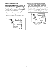
... is connected to your home stereo, see instruction B. Plug the adapter into the ANT. Plug the other end of the B cable into the adapter. IN VIDEO AUDIO IN CH 34 OUT RF OUT AUDIO OUT jack on page 18. IN VIDEO AUDIO IN CH 34 OUT RF OUT AUDIO OUT RIGHT LEFT Adapter Audio Cable RCA Y-adapter Audio Cable Adapter Wire removed from AUDIO OUT jack 19 A ANT. Plug the other end of the cable into...
... is connected to your home stereo, see instruction B. Plug the adapter into the ANT. Plug the other end of the B cable into the adapter. IN VIDEO AUDIO IN CH 34 OUT RF OUT AUDIO OUT jack on page 18. IN VIDEO AUDIO IN CH 34 OUT RF OUT AUDIO OUT RIGHT LEFT Adapter Audio Cable RCA Y-adapter Audio Cable Adapter Wire removed from AUDIO OUT jack 19 A ANT. Plug the other end of the cable into...

English Manual
Page 20
..., the console may not detect the program signals. • Make sure that the audio cable is fully plugged in almost the same way as a resistance and pace program (see step 3 on your CD player. See step 4 on , the manual mode will begin guiding you are using an iFIT.com CD, insert the CD into your VCR. 4 Press the play button is pressed, your personal trainer will be connected to...
..., the console may not detect the program signals. • Make sure that the audio cable is fully plugged in almost the same way as a resistance and pace program (see step 3 on your CD player. See step 4 on , the manual mode will begin guiding you are using an iFIT.com CD, insert the CD into your VCR. 4 Press the play button is pressed, your personal trainer will be connected to...
English Manual
Page 21
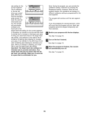
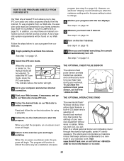
... displays. See step 4 on -screen countdown will light. 3 Go to the exercise cycle and begin . THE OPTIONAL CHEST PULSE SENSOR The optional chest pulse sensor provides hands-free operation and continuously monitors your heart rate during your heart rate if desired. When the on -line instructions to use programs from the internet. Follow the steps below to start the program, an on page 12. 9 Measure your workouts. When the console is about to change. 8 Monitor...
... displays. See step 4 on -screen countdown will light. 3 Go to the exercise cycle and begin . THE OPTIONAL CHEST PULSE SENSOR The optional chest pulse sensor provides hands-free operation and continuously monitors your heart rate during your heart rate if desired. When the on -line instructions to use programs from the internet. Follow the steps below to start the program, an on page 12. 9 Measure your workouts. When the console is about to change. 8 Monitor...
English Manual
Page 22
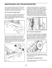
.... PULSE SENSOR TROUBLESHOOTING If the handgrip pulse sensor does not function properly, see step 5 on page 13. 22 Turn the Right Crank Arm for a moment. MAINTENANCE AND TROUBLESHOOTING Inspect and properly tighten all parts of the exercise cycle, and then slide off the Right Side Shield. 57 HOW TO ADJUST THE DRIVE BELT If you can feel the pedals slip while you must first be adjusted. To clean the exercise cycle, use...
.... PULSE SENSOR TROUBLESHOOTING If the handgrip pulse sensor does not function properly, see step 5 on page 13. 22 Turn the Right Crank Arm for a moment. MAINTENANCE AND TROUBLESHOOTING Inspect and properly tighten all parts of the exercise cycle, and then slide off the Right Side Shield. 57 HOW TO ADJUST THE DRIVE BELT If you can feel the pedals slip while you must first be adjusted. To clean the exercise cycle, use...
English Manual
Page 23
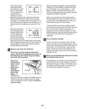
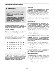
... workout should include the following guidelines will help you , first find the three numbers above your training zone. The lowest number is the recommended heart rate for fat burning; A cool-down, with pre-existing health problems. • The pulse sensor is activity that proper nutrition and adequate rest are your body temperature, heart rate, and circulation in preparation for a sustained period of your exercise program...
... workout should include the following guidelines will help you , first find the three numbers above your training zone. The lowest number is the recommended heart rate for fat burning; A cool-down, with pre-existing health problems. • The pulse sensor is activity that proper nutrition and adequate rest are your body temperature, heart rate, and circulation in preparation for a sustained period of your exercise program...
English Manual
Page 25
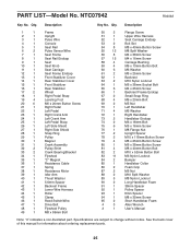
... Seat Frame Seat Rail Endcap Seat Seat Knob Seat Carriage Seat Frame Endcap Front Stabilizer Cover Rear Stabilizer Cover Front Stabilizer Rear Stabilizer Wheel Right Pedal Strap Leveling Foot M6 x 20mm Button Screw Right Pedal Left Pedal Right Crank Arm Left Crank Arm Left Pedal Strap Left Side Shield Right Side Shield Snap Ring Pulley Magnet Crank Assembly Pulley Shim Crank Bearing/Bracket Flywheel "C" Magnet Resistance Cable Spring Resistance Motor Idler Arm Thrust Washer 5.6mm Spacer Backrest Frame Lower Wire Harness Roller Clamp Reed Switch/Wire Drive Belt Flywheel Pulley M8 x 86mm Bolt...
... Seat Frame Seat Rail Endcap Seat Seat Knob Seat Carriage Seat Frame Endcap Front Stabilizer Cover Rear Stabilizer Cover Front Stabilizer Rear Stabilizer Wheel Right Pedal Strap Leveling Foot M6 x 20mm Button Screw Right Pedal Left Pedal Right Crank Arm Left Crank Arm Left Pedal Strap Left Side Shield Right Side Shield Snap Ring Pulley Magnet Crank Assembly Pulley Shim Crank Bearing/Bracket Flywheel "C" Magnet Resistance Cable Spring Resistance Motor Idler Arm Thrust Washer 5.6mm Spacer Backrest Frame Lower Wire Harness Roller Clamp Reed Switch/Wire Drive Belt Flywheel Pulley M8 x 86mm Bolt...
English Manual
Page 28
... information when calling: • the MODEL NUMBER of the product (NTC07942) • the NAME of the product (NordicTrack® SL 710 exercise cycle) • the SERIAL NUMBER of the product (see the front cover of this limited warranty. Include a letter explaining the product or problem and a copy of your proof of purchase if you believe the service is covered by an ICON trained and authorized service...
... information when calling: • the MODEL NUMBER of the product (NTC07942) • the NAME of the product (NordicTrack® SL 710 exercise cycle) • the SERIAL NUMBER of the product (see the front cover of this limited warranty. Include a letter explaining the product or problem and a copy of your proof of purchase if you believe the service is covered by an ICON trained and authorized service...


