
English Manual
Page 1
... DIRECT TO OUR TOLLFREE CUSTOMER HOT LINE. USER'S MANUAL Visit our website at www.nordictrack.com new products, prizes, fitness tips, and much more! If you have questions, or if there are missing or damaged parts, we are committed to providing complete customer satisfaction. MST CAUTION Read all precautions and instructions in the space above for future reference. Model...
... DIRECT TO OUR TOLLFREE CUSTOMER HOT LINE. USER'S MANUAL Visit our website at www.nordictrack.com new products, prizes, fitness tips, and much more! If you have questions, or if there are missing or damaged parts, we are committed to providing complete customer satisfaction. MST CAUTION Read all precautions and instructions in the space above for future reference. Model...
English Manual
Page 2
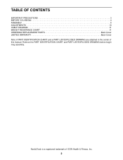
TABLE OF CONTENTS IMPORTANT PRECAUTIONS 3 BEFORE YOU BEGIN 4 ASSEMBLY 5 ADJUSTMENTS 10 CABLE DIAGRAM 11 WEIGHT RESISTANCE CHART 11 ORDERING REPLACEMENT PARTS Back Cover LIMITED WARRANTY Back Cover Note: A PART IDENTIFICATION CHART and a PART LIST/EXPLODED DRAWING are attached in the center of ICON Health & Fitness, Inc. 2 NordicTrack is a registered trademark of this manual. Remove the PART IDENTIFICATION CHART and PART LIST/EXPLODED DRAWING before beginning assembly.
TABLE OF CONTENTS IMPORTANT PRECAUTIONS 3 BEFORE YOU BEGIN 4 ASSEMBLY 5 ADJUSTMENTS 10 CABLE DIAGRAM 11 WEIGHT RESISTANCE CHART 11 ORDERING REPLACEMENT PARTS Back Cover LIMITED WARRANTY Back Cover Note: A PART IDENTIFICATION CHART and a PART LIST/EXPLODED DRAWING are attached in the center of ICON Health & Fitness, Inc. 2 NordicTrack is a registered trademark of this manual. Remove the PART IDENTIFICATION CHART and PART LIST/EXPLODED DRAWING before beginning assembly.
English Manual
Page 3
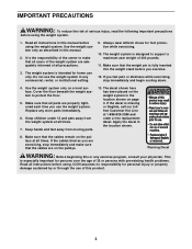
... placed on the pulleys at 1-888-825-2588 and order a free replacement decal. Replace any exercise program, consult your physician. Apply the decal in the location shown on a level surface. The weight system is missing or illegible, call our tollfree Customer Hot Line at all instructions in any commercial, rental, or institutional setting. 9. Cover the floor beneath the weight system to protect...
... placed on the pulleys at 1-888-825-2588 and order a free replacement decal. Replace any exercise program, consult your physician. Apply the decal in the location shown on a level surface. The weight system is missing or illegible, call our tollfree Customer Hot Line at all instructions in any commercial, rental, or institutional setting. 9. Cover the floor beneath the weight system to protect...
English Manual
Page 4
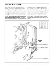
... goal is to the attachment (see the front cover of the lower body. The model number is designed to achieve the specific results you for selecting the versatile NordicTrack® GRT 950 weight system attachment. The serial number can be found on a decal attached to tone your body, build dramatic muscle size and strength, or improve your benefit, read this manual). Department toll-free at 1-888-825...
... goal is to the attachment (see the front cover of the lower body. The model number is designed to achieve the specific results you for selecting the versatile NordicTrack® GRT 950 weight system attachment. The serial number can be found on a decal attached to tone your body, build dramatic muscle size and strength, or improve your benefit, read this manual). Department toll-free at 1-888-825...
English Manual
Page 5
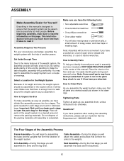
... will attach the cables and pulleys that form the skeleton of time and by assembling the base and the uprights that connect the arms to Unpack the Box To make sure to read it . The parts needed for the Weight System How to Identify Parts To help of evenings. Questions? Arm Assembly-During this page. Make sure you have the following tools: • Two adjustable...
... will attach the cables and pulleys that form the skeleton of time and by assembling the base and the uprights that connect the arms to Unpack the Box To make sure to read it . The parts needed for the Weight System How to Identify Parts To help of evenings. Questions? Arm Assembly-During this page. Make sure you have the following tools: • Two adjustable...
English Manual
Page 6
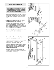
... (C). Attach the Hack Squat Upright (4) to the rear base (D) with four M10 x 25mm Bolts (31). 2 1 3. Secure the Hack Squat Base (1) to the left upright (G). Remove the indicated two M10 x 45mm bolts (E), two M10 washers (F), and two M10 Nylon Locknuts (C) from the rear base (D). 2. Press a 50mm Square Inner Cap (25) into the rear base (C). Do not tighten the Locknuts yet. Before beginning assembly...
... (C). Attach the Hack Squat Upright (4) to the rear base (D) with four M10 x 25mm Bolts (31). 2 1 3. Secure the Hack Squat Base (1) to the left upright (G). Remove the indicated two M10 x 45mm bolts (E), two M10 washers (F), and two M10 Nylon Locknuts (C) from the rear base (D). 2. Press a 50mm Square Inner Cap (25) into the rear base (C). Do not tighten the Locknuts yet. Before beginning assembly...

English Manual
Page 7
Tighten the M10 Locknuts (32) used in the Hack Squat Base (1) with two M10 x 95mm Bolts (38), two M10 Washers (36), and two M10 Locknuts (32). Press four 34mm Bushings (14) into the end of the Hack Squat Frame (5). Attach the Hack Squat Bumper (16) to the Hack Squat Upright (4)... 10 9 42 8 28 42 21 13 Attach the Hack Squat Leg (2) to the Hack Squat Frame (5) with an M4 Washer (37) and an M4 x 20mm Screw (29). 6. Arm Assembly 5 5. Attach the Release Handle (10) to the two M10 x 67mm Carriage Bolts (33) in steps 3 and 4. Press two 75mm x 50mm Inner Caps (21) ...
Tighten the M10 Locknuts (32) used in the Hack Squat Base (1) with two M10 x 95mm Bolts (38), two M10 Washers (36), and two M10 Locknuts (32). Press four 34mm Bushings (14) into the end of the Hack Squat Frame (5). Attach the Hack Squat Bumper (16) to the Hack Squat Upright (4)... 10 9 42 8 28 42 21 13 Attach the Hack Squat Leg (2) to the Hack Squat Frame (5) with an M4 Washer (37) and an M4 x 20mm Screw (29). 6. Arm Assembly 5 5. Attach the Release Handle (10) to the two M10 x 67mm Carriage Bolts (33) in steps 3 and 4. Press two 75mm x 50mm Inner Caps (21) ...
English Manual
Page 8
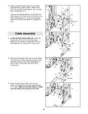
... Pin (12) with an M10 x 60mm Bolt (24), four M10 Washers (36), and an M10 Locknut (32). 5 12 10 31 Arm 30 3 31 15 30 32 3 19 24 36 36 20 10. Let go of the Release Handle so that the Cable is routed over the 11 Pulley (19) attached ...(3) with an M10 x 70mm Bolt (40) and an M10 Locknut (32). 11. Locate the Hack Squat Cable (20). Route the Hack Squat Cable (20) over the Pulley from the back to the Hack Squat Bracket (3) with a hole in step 9. Wrap the Hack Squat Cable (20) around a Pulley 10 (19). Cable Assembly 9 9. Attach the Cable and a Pulley (19) to the front. ...
... Pin (12) with an M10 x 60mm Bolt (24), four M10 Washers (36), and an M10 Locknut (32). 5 12 10 31 Arm 30 3 31 15 30 32 3 19 24 36 36 20 10. Let go of the Release Handle so that the Cable is routed over the 11 Pulley (19) attached ...(3) with an M10 x 70mm Bolt (40) and an M10 Locknut (32). 11. Locate the Hack Squat Cable (20). Route the Hack Squat Cable (20) over the Pulley from the back to the Hack Squat Bracket (3) with a hole in step 9. Wrap the Hack Squat Cable (20) around a Pulley 10 (19). Cable Assembly 9 9. Attach the Cable and a Pulley (19) to the front. ...
English Manual
Page 9
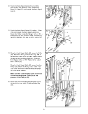
...Squat Upright (4) in step 10, and through the Hack Squat Upright (4). Route the Hack Squat Cable (20) under a Pulley 13 (19) and through the Hack Squat Leg (2). 13. Make sure the Cable Traps (18) are positioned to 15 the end of the Pulleys (19). 15. Attach the end of the Hack Squat Cable ...Squat Base (1) in the same manner. Wrap the Hack Squat Cable (20) around a Pulley 14 (19). Attach the Pulley and a Cable Trap (18) to the other Pulley (19) attached to the left hole in the grooves of the rear cable (F) with an M10 x 65mm Bolt (35), two 15mm x 12mm Spacers (17), two M10...
...Squat Upright (4) in step 10, and through the Hack Squat Upright (4). Route the Hack Squat Cable (20) under a Pulley 13 (19) and through the Hack Squat Leg (2). 13. Make sure the Cable Traps (18) are positioned to 15 the end of the Pulleys (19). 15. Attach the end of the Hack Squat Cable ...Squat Base (1) in the same manner. Wrap the Hack Squat Cable (20) around a Pulley 14 (19). Attach the Pulley and a Cable Trap (18) to the other Pulley (19) attached to the left hole in the grooves of the rear cable (F) with an M10 x 65mm Bolt (35), two 15mm x 12mm Spacers (17), two M10...
English Manual
Page 10
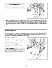
Seat Assembly 16 16. Make sure all parts have been properly tightened. ADJUSTING THE HACK SQUAT Stand on the foot plate on page 11 for proper cable routing. Release the Handle, and engage the Hack Squat Pin (12) into an adjustment hole in the Hack Squat Bracket (3). Attach the Hack Squat Backrest (6) to make sure that all parts are not properly installed, they...
Seat Assembly 16 16. Make sure all parts have been properly tightened. ADJUSTING THE HACK SQUAT Stand on the foot plate on page 11 for proper cable routing. Release the Handle, and engage the Hack Squat Pin (12) into an adjustment hole in the Hack Squat Bracket (3). Attach the Hack Squat Backrest (6) to make sure that all parts are not properly installed, they...

English Manual
Page 11
... 5-lb. "Top" refers to differences in individual weight plates, as well as friction between the cables, pulleys, and weight guides. The numbers show the correct route for the hack squat station. Hack Squat Cable (20) 7 6 3 1 8 5 4 2 WEIGHT RESISTANCE CHART This chart shows the approximate weight resistance for the cable. Note: The actual resistance may occur. Use the diagram to the seven 5-lb. weight plates and the sixteen 10lb. The other...
... 5-lb. "Top" refers to differences in individual weight plates, as well as friction between the cables, pulleys, and weight guides. The numbers show the correct route for the hack squat station. Hack Squat Cable (20) 7 6 3 1 8 5 4 2 WEIGHT RESISTANCE CHART This chart shows the approximate weight resistance for the cable. Note: The actual resistance may occur. Use the diagram to the seven 5-lb. weight plates and the sixteen 10lb. The other...
English Manual
Page 12
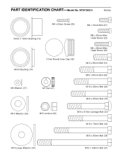
PART IDENTIFICATION CHART-Model No. NTSY39210 R0303A M4 x 20mm Screw (29) 34mm x 19mm Bushing (13) 34mm Bushing (14) 31mm Round Inner Cap (42) M4 Washer (37) M7 Nut (47) M6 x 16mm Bolt (27) M6 x 20mm Allen Head Screw (23) M6 x 25mm Allen Head Screw (28) M10 x 25mm Bolt (31) M10 x 50mm Bolt (39) M10 x 60mm Bolt (24) M10 x 65mm Bolt (35) M10 Washer (36) M10 Locknut (32) M10 Large Washer (30) M10 x 67mm Carriage Bolt (33) M10 x 70mm Bolt (40) M10 x 95mm Bolt (38) M10 x 125mm Bolt (41)
PART IDENTIFICATION CHART-Model No. NTSY39210 R0303A M4 x 20mm Screw (29) 34mm x 19mm Bushing (13) 34mm Bushing (14) 31mm Round Inner Cap (42) M4 Washer (37) M7 Nut (47) M6 x 16mm Bolt (27) M6 x 20mm Allen Head Screw (23) M6 x 25mm Allen Head Screw (28) M10 x 25mm Bolt (31) M10 x 50mm Bolt (39) M10 x 60mm Bolt (24) M10 x 65mm Bolt (35) M10 Washer (36) M10 Locknut (32) M10 Large Washer (30) M10 x 67mm Carriage Bolt (33) M10 x 70mm Bolt (40) M10 x 95mm Bolt (38) M10 x 125mm Bolt (41)
English Manual
Page 13
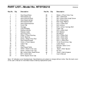
... Bolt 36 10 M10 Washer 37 1 M4 Washer 38 2 M10 x 95mm Bolt 39 2 M10 x 50mm Bolt 40 1 M10 x 70mm Bolt 41 2 M10 x 125mm Bolt 42 2 31mm Round Inner Cap 43 1 Cable Attach 44 1 Release Cable Cover 45 1 Spring 46 2 15mm x 8mm Spacer 47 2 M7 Nut 48 1 75mm x 50mm Spacer # 1 User's Manual Note: "#" indicates a non-illustrated part. Qty. NTSY39210 R0303A Key No. PART LIST-Model No. Description Key...
... Bolt 36 10 M10 Washer 37 1 M4 Washer 38 2 M10 x 95mm Bolt 39 2 M10 x 50mm Bolt 40 1 M10 x 70mm Bolt 41 2 M10 x 125mm Bolt 42 2 31mm Round Inner Cap 43 1 Cable Attach 44 1 Release Cable Cover 45 1 Spring 46 2 15mm x 8mm Spacer 47 2 M7 Nut 48 1 75mm x 50mm Spacer # 1 User's Manual Note: "#" indicates a non-illustrated part. Qty. NTSY39210 R0303A Key No. PART LIST-Model No. Description Key...
English Manual
Page 14
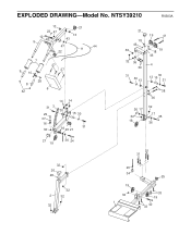
EXPLODED DRAWING-Model No. NTSY39210 R0303A 13 21 23 47 12 45 5 13 43 47 44 11 22 7 9 10 27 27 8 42 28 6 31 3 29 37 16 32 14 14 30 15 30 36 20 21 31 21 18 46 36 32 36 39 31 30 13 19 41 19 18 46 4 13 30 15 31 38 36 36 17 32 19 32 17 35 36 21 19 36 24 31 31 32 26 48 32 2 32 32 20 34 19 32 1 25 33 19 33 40
EXPLODED DRAWING-Model No. NTSY39210 R0303A 13 21 23 47 12 45 5 13 43 47 44 11 22 7 9 10 27 27 8 42 28 6 31 3 29 37 16 32 14 14 30 15 30 36 20 21 31 21 18 46 36 32 36 39 31 30 13 19 41 19 18 46 4 13 30 15 31 38 36 36 17 32 19 32 17 35 36 21 19 36 24 31 31 32 26 48 32 2 32 32 20 34 19 32 1 25 33 19 33 40
English Manual
Page 15
... SERIAL NUMBER of the product (see the PART LIST and EXPLODED DRAWING at the center of this manual) LIMITED WARRANTY WHAT IS COVERED-The entire NordicTrack® GRT 950 weight system attachment ("Product") is located or advise you may have other warranties and any economic loss, loss of property, loss of revenues or profits, loss of enjoyment or use, costs of removal, installation or other parts for repair...
... SERIAL NUMBER of the product (see the PART LIST and EXPLODED DRAWING at the center of this manual) LIMITED WARRANTY WHAT IS COVERED-The entire NordicTrack® GRT 950 weight system attachment ("Product") is located or advise you may have other warranties and any economic loss, loss of property, loss of revenues or profits, loss of enjoyment or use, costs of removal, installation or other parts for repair...


