
English Manual
Page 1
... DELAYS, PLEASE CALL DIRECT TO OUR TOLLFREE CUSTOMER HOT LINE. CUSTOMER HOT LINE: 1-888-825-2588 Mon.-Fri., 6 a.m.-6 p.m. USER'S MANUAL Visit our website at www.nordictrack.com new products, prizes, fitness tips, and much more!
... DELAYS, PLEASE CALL DIRECT TO OUR TOLLFREE CUSTOMER HOT LINE. CUSTOMER HOT LINE: 1-888-825-2588 Mon.-Fri., 6 a.m.-6 p.m. USER'S MANUAL Visit our website at www.nordictrack.com new products, prizes, fitness tips, and much more!
English Manual
Page 2
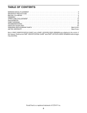
Remove the PART IDENTIFICATION CHART and PART LIST/EXPLODED DRAWING before beginning assembly. NordicTrack is a registered trademark of this manual. TABLE OF CONTENTS WARNING DECAL PLACEMENT 3 IMPORTANT PRECAUTIONS 4 BEFORE YOU BEGIN 5 ASSEMBLY 6 UPPER CABLE ADJUSTMENT 14 ADJUSTMENTS 15 CABLE DIAGRAM 18 TROUBLESHOOTING 19 EXERCISE GUIDELINES 20 ORDERING REPLACEMENT PARTS Back Cover LIMITED WARRANTY Back Cover Note: A PART IDENTIFICATION CHART and a PART LIST/EXPLODED DRAWING are attached in the center of ICON IP, Inc. 2
Remove the PART IDENTIFICATION CHART and PART LIST/EXPLODED DRAWING before beginning assembly. NordicTrack is a registered trademark of this manual. TABLE OF CONTENTS WARNING DECAL PLACEMENT 3 IMPORTANT PRECAUTIONS 4 BEFORE YOU BEGIN 5 ASSEMBLY 6 UPPER CABLE ADJUSTMENT 14 ADJUSTMENTS 15 CABLE DIAGRAM 18 TROUBLESHOOTING 19 EXERCISE GUIDELINES 20 ORDERING REPLACEMENT PARTS Back Cover LIMITED WARRANTY Back Cover Note: A PART IDENTIFICATION CHART and a PART LIST/EXPLODED DRAWING are attached in the center of ICON IP, Inc. 2

English Manual
Page 3
until 6 p.m. Mountain Time, to order a free replacement decal. Apply the decal in the location shown. If a decal is missing or illegible, please call our Customer Service Department tollfree at 1-888-825-2588, Monday through Friday, 6 a.m. Keep hands and fingers clear of this area. 3 WARNING DECAL PLACEMENT The decals shown here have been placed on the resistance system.
until 6 p.m. Mountain Time, to order a free replacement decal. Apply the decal in the location shown. If a decal is missing or illegible, please call our Customer Service Department tollfree at 1-888-825-2588, Monday through Friday, 6 a.m. Keep hands and fingers clear of this area. 3 WARNING DECAL PLACEMENT The decals shown here have been placed on the resistance system.

English Manual
Page 4
Do not use of 300 pounds. 10. Replace any commercial, rental, or institutional setting. 11. Keep hands and feet away from the high cables when performing an exercise that all times. Make sure that the cables remain on the pulleys at least every two years. 16. Replace all cables at all parts are on the pulleys. WARNING: Before beginning this product. 4 This is especially important for persons over the age of 35 or persons with any other type of resistance. 4. The resistance system is used with the seat in one of all users of the resistance system are adequately ...
Do not use of 300 pounds. 10. Replace any commercial, rental, or institutional setting. 11. Keep hands and feet away from the high cables when performing an exercise that all times. Make sure that the cables remain on the pulleys at least every two years. 16. Replace all cables at all parts are on the pulleys. WARNING: Before beginning this product. 4 This is especially important for persons over the age of 35 or persons with any other type of resistance. 4. The resistance system is used with the seat in one of all users of the resistance system are adequately ...
English Manual
Page 5
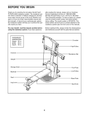
... with the parts that are labeled. Width: 66 in . until 6 p.m. Depth: 80 in . Whether your goal is NTS58740. If you for selecting the innovative NordicTrack® FUTURA 2200 resistance system. The model number is to tone your body, build dramatic muscle size and strength, or improve your benefit, read this manual). ASSEMBLED DIMENSIONS...
... with the parts that are labeled. Width: 66 in . until 6 p.m. Depth: 80 in . Whether your goal is NTS58740. If you for selecting the innovative NordicTrack® FUTURA 2200 resistance system. The model number is to tone your body, build dramatic muscle size and strength, or improve your benefit, read this manual). ASSEMBLED DIMENSIONS...
English Manual
Page 6
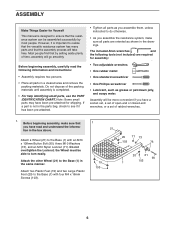
The included Allen wrenches and the following information and instructions: • Assembly requires two persons. • Place all parts in a cleared area and remove the packing materials. However, it has been pre-attached. • Tighten all parts are required for assembly: • Two adjustable wrenches • One rubber mallet • One standard screwdriver • One Phillips screwdriver • Lubricant, such as you assemble them, unless instructed to do otherwise. • As you assemble the resistance system, make sure that 1 you have been pre-attached ...
The included Allen wrenches and the following information and instructions: • Assembly requires two persons. • Place all parts in a cleared area and remove the packing materials. However, it has been pre-attached. • Tighten all parts are required for assembly: • Two adjustable wrenches • One rubber mallet • One standard screwdriver • One Phillips screwdriver • Lubricant, such as you assemble them, unless instructed to do otherwise. • As you assemble the resistance system, make sure that 1 you have been pre-attached ...

English Manual
Page 7
Attach the Upright (3) to the Base (1) with 3 three M10 x 70mm Carriage Bolts (88), three M10 Washers (73), and three M10 Nylon Locknuts (71). 4 88 3 73 71 71 73 7 2. Note: This step will be easier to the Upright (3) with two 2 M10 x 66mm Carriage Bolts (89), two M10 x 72mm Bolts (87), and four M10 Nylon Locknuts (71) as shown. Attach the Foot Plate (4) to complete if the Upright and Base are tipped on their sides. 3 87 71 71 71 1 89 3.
Attach the Upright (3) to the Base (1) with 3 three M10 x 70mm Carriage Bolts (88), three M10 Washers (73), and three M10 Nylon Locknuts (71). 4 88 3 73 71 71 73 7 2. Note: This step will be easier to the Upright (3) with two 2 M10 x 66mm Carriage Bolts (89), two M10 x 72mm Bolts (87), and four M10 Nylon Locknuts (71) as shown. Attach the Foot Plate (4) to complete if the Upright and Base are tipped on their sides. 3 87 71 71 71 1 89 3.

English Manual
Page 8
Attach the Mech Assembly to the Upright (3) with the Bolt and an M10 Nylon Locknut (71). the Bench Rail must be able to the Front Leg (31) with four M10 Nylon Locknuts (71). The connector should slide easily into the socket and snap into place, turn the connector over and then insert it and the Upper Wire Harness (13) into the socket of the Upper Wire Harness (13). Make sure that the front of the Mech Assembly (6) and push it . Attach the Bench Rail (23) to the Base (1) with two M10 x 53mm Carriage Bolts (91) and two M10 Nylon Locknuts (71). 4 13 3 79 6 78 108 13 ...
Attach the Mech Assembly to the Upright (3) with the Bolt and an M10 Nylon Locknut (71). the Bench Rail must be able to the Front Leg (31) with four M10 Nylon Locknuts (71). The connector should slide easily into the socket and snap into place, turn the connector over and then insert it and the Upper Wire Harness (13) into the socket of the Upper Wire Harness (13). Make sure that the front of the Mech Assembly (6) and push it . Attach the Bench Rail (23) to the Base (1) with two M10 x 53mm Carriage Bolts (91) and two M10 Nylon Locknuts (71). 4 13 3 79 6 78 108 13 ...
English Manual
Page 9
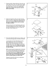
7. Grease an M10 x 69mm Bolt (93). Attach the Seat Knob (43) to the Seat Carriage 8 (48) with the Bolt and an M10 Nylon Locknut (71). Pull out the Seat Knob (43) as far as shown. Make sure that the serrated edges of all six Bearing Wheels (46) are against the Seat Carriage. Make sure that three threads are extending past the Nuts, and that the slot in the Knob is aligned with the slot in the Seat Carriage (48) with two M8 Flange Nuts (47) and the M8 x 114mm Axle (102). Do not over- Make sure that the wide sides of the Flange Nuts are pressed against the bottom of the Bench Rail...
7. Grease an M10 x 69mm Bolt (93). Attach the Seat Knob (43) to the Seat Carriage 8 (48) with the Bolt and an M10 Nylon Locknut (71). Pull out the Seat Knob (43) as far as shown. Make sure that the serrated edges of all six Bearing Wheels (46) are against the Seat Carriage. Make sure that three threads are extending past the Nuts, and that the slot in the Knob is aligned with the slot in the Seat Carriage (48) with two M8 Flange Nuts (47) and the M8 x 114mm Axle (102). Do not over- Make sure that the wide sides of the Flange Nuts are pressed against the bottom of the Bench Rail...

English Manual
Page 10
Make sure that the Eyebolts (51) are not, turn the Lat Tower Crossbar around and reattach it. 12. Make sure the wire does not get pinched. Attach two Eyebolts (51) to the Upright (3) with an M12 x 62mm Button Bolt (80) and an M12 Nylon Locknut (72). If they are oriented as shown in the inset drawing. Attach a Large Pulley (17) and the Pulley Plate (18) to the Lat Tower Crossbar (49) with 10 four M10 x 25mm Screws (100) and four M10 Lock Washers (74). Do not tighten the Locknut yet. 74 100 103 13 53 3 103 11 96 70 76 73 50 100 74 51 49 Side View 5 51 12 49...
Make sure that the Eyebolts (51) are not, turn the Lat Tower Crossbar around and reattach it. 12. Make sure the wire does not get pinched. Attach two Eyebolts (51) to the Upright (3) with an M12 x 62mm Button Bolt (80) and an M12 Nylon Locknut (72). If they are oriented as shown in the inset drawing. Attach a Large Pulley (17) and the Pulley Plate (18) to the Lat Tower Crossbar (49) with 10 four M10 x 25mm Screws (100) and four M10 Lock Washers (74). Do not tighten the Locknut yet. 74 100 103 13 53 3 103 11 96 70 76 73 50 100 74 51 49 Side View 5 51 12 49...

English Manual
Page 11
Hold the 38mm Spacer (54) inside the loop of the Upper Cable (110), and between the two Pulleys. Do not tighten the Bolt yet. Do not tighten 15 the Bolt yet. 15. Make sure that the Upper Cable (110) is attached 13 inside the Upper Cable (110). Press the metal cover on the Cable into the groove in the CABLE DIAGRAM on page 18. 80 63 110 85 54 72 17 18 57 56 55 83 Metal Cover 75 83 5 61 110 56 58 55 61 71 9 82 75 10 10 72 81 17 110 11 Attach a Tether (61) to the Lat Tower (5) with an M10 x 63mm Button Bolt (82), an M10 Thick Washer (75), and an M10...
Hold the 38mm Spacer (54) inside the loop of the Upper Cable (110), and between the two Pulleys. Do not tighten the Bolt yet. Do not tighten 15 the Bolt yet. 15. Make sure that the Upper Cable (110) is attached 13 inside the Upper Cable (110). Press the metal cover on the Cable into the groove in the CABLE DIAGRAM on page 18. 80 63 110 85 54 72 17 18 57 56 55 83 Metal Cover 75 83 5 61 110 56 58 55 61 71 9 82 75 10 10 72 81 17 110 11 Attach a Tether (61) to the Lat Tower (5) with an M10 x 63mm Button Bolt (82), an M10 Thick Washer (75), and an M10...

English Manual
Page 12
Make sure the hexagonal holes in the Screws are on the Backrest Frame (36) into the slot in the Seat Carriage (48). Insert the rod on the outside of the Brackets. Hold a Large Pulley (17) inside of the Upper Cable (110). Attach the Pulley to a Pulley Bracket (10) with four M6 x 45mm Screws (98). 17 110 81 18 40 39 10 72 106 17 36 98 98 19. Tighten the two Screws an equal number of turns. Attach the Backrest (40) and the Backrest Backing (39) to the inside of 19 the Backrest Frame (36) with four M4 x 16mm Screws (103). 36 20. Make sure that the Cable is routed as shown...
Make sure the hexagonal holes in the Screws are on the Backrest Frame (36) into the slot in the Seat Carriage (48). Insert the rod on the outside of the Brackets. Hold a Large Pulley (17) inside of the Upper Cable (110). Attach the Pulley to a Pulley Bracket (10) with four M6 x 45mm Screws (98). 17 110 81 18 40 39 10 72 106 17 36 98 98 19. Tighten the two Screws an equal number of turns. Attach the Backrest (40) and the Backrest Backing (39) to the inside of 19 the Backrest Frame (36) with four M4 x 16mm Screws (103). 36 20. Make sure that the Cable is routed as shown...

English Manual
Page 13
Route the longest end of the Leg Lever Cable (62) through the hole in the Front Leg (31), and attach it moves smoothly over the pulleys. Slide two Foam Pads (28) onto the tube on page 18 for proper cable routing. 13 Before using the resistance system, pull the long cable a few times to the bottom of the tube. See the CABLE DIAGRAM on the Front Leg (31). Make sure the Pulley is used. Press two 19mm Round Inner Caps (33) into the ends of the Bench Rail (23). 23. MENT on the Upper Cable (not 32 shown) as described in the Front Leg (31) with an M10 x 58mm Bolt (94) and an...
Route the longest end of the Leg Lever Cable (62) through the hole in the Front Leg (31), and attach it moves smoothly over the pulleys. Slide two Foam Pads (28) onto the tube on page 18 for proper cable routing. 13 Before using the resistance system, pull the long cable a few times to the bottom of the tube. See the CABLE DIAGRAM on the Front Leg (31). Make sure the Pulley is used. Press two 19mm Round Inner Caps (33) into the ends of the Bench Rail (23). 23. MENT on the Upper Cable (not 32 shown) as described in the Front Leg (31) with an M10 x 58mm Bolt (94) and an...

English Manual
Page 14
UPPER CABLE ADJUSTMENT After the resistance system is assembled, the tension on the Upper Cable (110) will need to be readjusted. Hook the ends of the Resistance Bar (9). Connect the two Tension Gauges (107) using the 1 magnet. 107 Magnet 107 2. Squeeze the Upper Cable (110) together near a Large Pulley (17). Follow the steps below to the Large Pulley (17) as shown. Locate the 3/8" x 38mm Tension Screw (106) on each Screw one turn at a time until the two Tension Gauges (107) are pulled apart by the Upper Cable (110). Use the Console (not shown) to adjust the ...
UPPER CABLE ADJUSTMENT After the resistance system is assembled, the tension on the Upper Cable (110) will need to be readjusted. Hook the ends of the Resistance Bar (9). Connect the two Tension Gauges (107) using the 1 magnet. 107 Magnet 107 2. Squeeze the Upper Cable (110) together near a Large Pulley (17). Follow the steps below to the Large Pulley (17) as shown. Locate the 3/8" x 38mm Tension Screw (106) on each Screw one turn at a time until the two Tension Gauges (107) are pulled apart by the Upper Cable (110). Use the Console (not shown) to adjust the ...

English Manual
Page 15
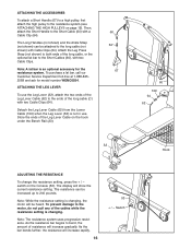
ADJUSTMENTS This section explains how to roll along the Bench Rail (23). The resistance system can be cleaned with a vinyl and rubber protectant, available at the end of the Lower Cable (109) with a damp cloth and a mild, non-abrasive detergent. ATTACHING THE HIGH PULLEYS To use a high pulley, slide the hook on the Bench Rail (23). To perform row exercises, the leg press strap must be attached to the long cable (see ADJUSTING THE BACKREST on page 16), and the Seat Carriage (48) must be secured in order to see the inset drawing). 15 64 109 40 41 48 23 43 "L"-...
ADJUSTMENTS This section explains how to roll along the Bench Rail (23). The resistance system can be cleaned with a vinyl and rubber protectant, available at the end of the Lower Cable (109) with a damp cloth and a mild, non-abrasive detergent. ATTACHING THE HIGH PULLEYS To use a high pulley, slide the hook on the Bench Rail (23). To perform row exercises, the leg press strap must be attached to the long cable (see ADJUSTING THE BACKREST on page 16), and the Seat Carriage (48) must be secured in order to see the inset drawing). 15 64 109 40 41 48 23 43 "L"-...
English Manual
Page 16
Detach the Leg Lever Cable (62) from the Lower Cable (109) when the Leg Lever (32) is changing. The display will increase rapidly. 16 53 + / - Attach the Leg Press Strap (not shown) to both ends of the long cable, or the optional lat bar to the long cable (not shown) with a Cable Clip (64). Store the ends of the cables while the resistance setting is not in use the Leg Lever (32), attach the two ends of the Leg Lever Cable (62) to 240 pounds. Note: The resistance system uses progressive resistance. Switch ATTACHING THE ACCESSORIES To attach a Short Handle (67) to a high pulley...
Detach the Leg Lever Cable (62) from the Lower Cable (109) when the Leg Lever (32) is changing. The display will increase rapidly. 16 53 + / - Attach the Leg Press Strap (not shown) to both ends of the long cable, or the optional lat bar to the long cable (not shown) with a Cable Clip (64). Store the ends of the cables while the resistance setting is not in use the Leg Lever (32), attach the two ends of the Leg Lever Cable (62) to 240 pounds. Note: The resistance system uses progressive resistance. Switch ATTACHING THE ACCESSORIES To attach a Short Handle (67) to a high pulley...

English Manual
Page 17
For row exercises, remove the Backrest (40). Next, remove the Storage Knob (26) from the Upright (3). Hold the Backrest vertically over the Seat (41) and lift the rod out of the Transformer (12) into a 120-volt outlet. PLUGGING IN THE RESISTANCE SYSTEM Plug the indicated end of the slot in the position closest to let the Front Leg (31) or Leg Lever (32) pinch your shoe on page 15). Important: Always plug in this area 3 26 41 32 62 23 31 1 21 Hook 8 12 17 Secure the Seat (41) in the Seat Carriage (48) (see ADJUSTING THE SEAT on the bottom of the Transformer into ...
For row exercises, remove the Backrest (40). Next, remove the Storage Knob (26) from the Upright (3). Hold the Backrest vertically over the Seat (41) and lift the rod out of the Transformer (12) into a 120-volt outlet. PLUGGING IN THE RESISTANCE SYSTEM Plug the indicated end of the slot in the position closest to let the Front Leg (31) or Leg Lever (32) pinch your shoe on page 15). Important: Always plug in this area 3 26 41 32 62 23 31 1 21 Hook 8 12 17 Secure the Seat (41) in the Seat Carriage (48) (see ADJUSTING THE SEAT on the bottom of the Transformer into ...

English Manual
Page 18
If the Cable has not been correctly routed, the resistance system will not function properly and damage may occur. Make sure that the Cable has been assembled correctly. Use the diagram to make sure that the ends of the Upper Cable (110). Upper Cable (110) 4 5 6 7 2 1 3 18 The numbers show the correct route for the Cable. CABLE DIAGRAM The cable diagram shows the proper routing of the Cable do not wrap around each other between positions 1 and 2, and 6 and 7.
If the Cable has not been correctly routed, the resistance system will not function properly and damage may occur. Make sure that the Cable has been assembled correctly. Use the diagram to make sure that the ends of the Upper Cable (110). Upper Cable (110) 4 5 6 7 2 1 3 18 The numbers show the correct route for the Cable. CABLE DIAGRAM The cable diagram shows the proper routing of the Cable do not wrap around each other between positions 1 and 2, and 6 and 7.

English Manual
Page 19
If the motor has difficulty adjusting the resistance level and no cable is being pulled, there may build up on the Bar Guides (55), causing a squeaking noise as described below. Select the desired resistance setting. If this step if necessary. 55 110 106 19 Repeat this occurs, wipe off the Bar Guides with a damp cloth and a mild, non-abrasive detergent. Do not use solvents. To prevent damage to the motor, do not pull any of the cables while the resistance setting is used. Adjust the tension as the resistance system is changing. To decrease the tension on the Upper Cable (...
If the motor has difficulty adjusting the resistance level and no cable is being pulled, there may build up on the Bar Guides (55), causing a squeaking noise as described below. Select the desired resistance setting. If this step if necessary. 55 110 106 19 Repeat this occurs, wipe off the Bar Guides with a damp cloth and a mild, non-abrasive detergent. Do not use solvents. To prevent damage to the motor, do not pull any of the cables while the resistance setting is used. Adjust the tension as the resistance system is changing. To decrease the tension on the Upper Cable (...
English Manual
Page 20
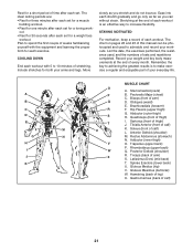
out. • Rest for 30 seconds after each exercise. Plan to schedule and record your weight and key body measurements at the end of each set. Include stretches for both your everyday life. The chart on pages 22 and 23 of weeks familiarizing yourself with 5 to increase flexibility. Sternomastoid (neck) B. Biceps (front of each workout with the equipment and learning the proper form for each set for a toning work- Anterior Deltoid (shoulder) M. COOLING DOWN End each workout. STAYING MOTIVATED For motivation, keep a record of arm) D. Record your workouts....
out. • Rest for 30 seconds after each exercise. Plan to schedule and record your weight and key body measurements at the end of each set. Include stretches for both your everyday life. The chart on pages 22 and 23 of weeks familiarizing yourself with 5 to increase flexibility. Sternomastoid (neck) B. Biceps (front of each workout with the equipment and learning the proper form for each set for a toning work- Anterior Deltoid (shoulder) M. COOLING DOWN End each workout. STAYING MOTIVATED For motivation, keep a record of arm) D. Record your workouts....