
English Manual
Page 1
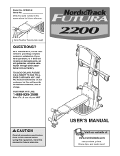
... guarantee complete satisfaction through direct assistance from our factory. USER'S MANUAL Visit our website at www.nordictrack.com new products, prizes, fitness tips, and much more! Model No. Write the serial number in this manual before using this manual for future reference. NTS58740 Serial No. Save this equipment. Serial Number Decal (under seat) QUESTIONS? As a manufacturer, we will provide immediate assistance, free of charge. If you...
... guarantee complete satisfaction through direct assistance from our factory. USER'S MANUAL Visit our website at www.nordictrack.com new products, prizes, fitness tips, and much more! Model No. Write the serial number in this manual before using this manual for future reference. NTS58740 Serial No. Save this equipment. Serial Number Decal (under seat) QUESTIONS? As a manufacturer, we will provide immediate assistance, free of charge. If you...
English Manual
Page 2
TABLE OF CONTENTS WARNING DECAL PLACEMENT 3 IMPORTANT PRECAUTIONS 4 BEFORE YOU BEGIN 5 ASSEMBLY 6 UPPER CABLE ADJUSTMENT 14 ADJUSTMENTS 15 CABLE DIAGRAM 18 TROUBLESHOOTING 19 EXERCISE GUIDELINES 20 ORDERING REPLACEMENT PARTS Back Cover LIMITED WARRANTY Back Cover Note: A PART IDENTIFICATION CHART and a PART LIST/EXPLODED DRAWING are attached in the center of ICON IP, Inc. 2 NordicTrack is a registered trademark of this manual. Remove the PART IDENTIFICATION CHART and PART LIST/EXPLODED DRAWING before beginning assembly.
TABLE OF CONTENTS WARNING DECAL PLACEMENT 3 IMPORTANT PRECAUTIONS 4 BEFORE YOU BEGIN 5 ASSEMBLY 6 UPPER CABLE ADJUSTMENT 14 ADJUSTMENTS 15 CABLE DIAGRAM 18 TROUBLESHOOTING 19 EXERCISE GUIDELINES 20 ORDERING REPLACEMENT PARTS Back Cover LIMITED WARRANTY Back Cover Note: A PART IDENTIFICATION CHART and a PART LIST/EXPLODED DRAWING are attached in the center of ICON IP, Inc. 2 NordicTrack is a registered trademark of this manual. Remove the PART IDENTIFICATION CHART and PART LIST/EXPLODED DRAWING before beginning assembly.

English Manual
Page 4
... the bench, with the included resistance. Cover the floor beneath the resistance system to support a maximum user weight of resistance. 4. Make sure that all precautions. 3. The crossbar on the base plate. 12. If you purchase the optional lat bar, always disconnect the lat bar from the high cables when performing an exercise that all users of the resistance system are adequately informed of all parts are properly tightened each...
... the bench, with the included resistance. Cover the floor beneath the resistance system to support a maximum user weight of resistance. 4. Make sure that all precautions. 3. The crossbar on the base plate. 12. If you purchase the optional lat bar, always disconnect the lat bar from the high cables when performing an exercise that all users of the resistance system are adequately informed of all parts are properly tightened each...
English Manual
Page 5
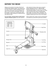
Width: 66 in . The model number is to the resistance system (see the front cover of the body. Before reading further, please review the drawing below and familiarize yourself with the parts that are labeled. ASSEMBLED DIMENSIONS: Height: 82 in . Console Upright Storage Knob Backrest Seat Leg Lever Crossbar High Pulley Resistance Bar Foot Plate Low Pulley Base Plate Seat Knob 5 For your cardiovascular system, the resistance system will help us assist you...
Width: 66 in . The model number is to the resistance system (see the front cover of the body. Before reading further, please review the drawing below and familiarize yourself with the parts that are labeled. ASSEMBLED DIMENSIONS: Height: 82 in . Console Upright Storage Knob Backrest Seat Leg Lever Crossbar High Pulley Resistance Bar Foot Plate Low Pulley Base Plate Seat Knob 5 For your cardiovascular system, the resistance system will help us assist you...
English Manual
Page 6
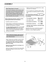
... following information and instructions: • Assembly requires two persons. • Place all parts are required for assembly: • Two adjustable wrenches • One rubber mallet • One standard screwdriver • One Phillips screwdriver • Lubricant, such as you assemble them, unless instructed to do otherwise. • As you assemble the resistance system, make sure that the resistance system can be assembled successfully by setting...
... following information and instructions: • Assembly requires two persons. • Place all parts are required for assembly: • Two adjustable wrenches • One rubber mallet • One standard screwdriver • One Phillips screwdriver • Lubricant, such as you assemble them, unless instructed to do otherwise. • As you assemble the resistance system, make sure that the resistance system can be assembled successfully by setting...

English Manual
Page 8
... PROPERLY, THE CONSOLE MAY BE DAMAGED WHEN THE POWER IS TURNED ON. Do not tighten the Locknut yet. Grease an M10 x 103mm Bolt (86) using the 6 included grease pack. Make sure the Bolt is taller than the back. Tighten the Storage Knob (26) into the socket of the Front Leg (31). Press the Front Leg Foot (29) onto the bottom of the Upper Wire Harness (13...
... PROPERLY, THE CONSOLE MAY BE DAMAGED WHEN THE POWER IS TURNED ON. Do not tighten the Locknut yet. Grease an M10 x 103mm Bolt (86) using the 6 included grease pack. Make sure the Bolt is taller than the back. Tighten the Storage Knob (26) into the socket of the Front Leg (31). Press the Front Leg Foot (29) onto the bottom of the Upper Wire Harness (13...
English Manual
Page 9
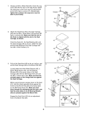
... the Flange Nuts are pressed against the Bench Rail. Engage the Seat Knob (43) into an adjustment hole in the Seat Carriage (48) with the slot on the Bench Rail (23). Do not over- While a second person presses down on the Seat (41), hold the wheel assembly firmly against the Seat Carriage. Attach the Leg Lever to the Front Leg (31) with the slot...
... the Flange Nuts are pressed against the Bench Rail. Engage the Seat Knob (43) into an adjustment hole in the Seat Carriage (48) with the slot on the Bench Rail (23). Do not over- While a second person presses down on the Seat (41), hold the wheel assembly firmly against the Seat Carriage. Attach the Leg Lever to the Front Leg (31) with the slot...

English Manual
Page 11
... Upright (3) and the Pulley Plate (18) with an M10 x 58mm Button Screw (85). Press the metal cover on the Block Spacer (not shown). Press a Pulley Bracket (10) onto the Resistance Bar (9). 13. Attach the Pulley to the Lat Tower (5) with an M12 x 58mm Button Bolt (81) and an M12 Nylon Locknut (72). Make sure that the Cable is routed as shown in steps 12 and 13 (see the CABLE DIAGRAM...
... Upright (3) and the Pulley Plate (18) with an M10 x 58mm Button Screw (85). Press the metal cover on the Block Spacer (not shown). Press a Pulley Bracket (10) onto the Resistance Bar (9). 13. Attach the Pulley to the Lat Tower (5) with an M12 x 58mm Button Bolt (81) and an M12 Nylon Locknut (72). Make sure that the Cable is routed as shown in steps 12 and 13 (see the CABLE DIAGRAM...

English Manual
Page 12
... 106 17 36 98 98 19. Attach the Backrest (40) and the Backrest Backing (39) to the inside of turns. 18. Hold the Backrest Frame vertically over the Seat Carriage and slide the rod into the slot in the CABLE DIAGRAM on the outside of turns. Insert the rod on the Backrest ...48 17. Screw two 3/8" x 38mm Tension Screws (106) into the two Pulley Brackets (10) a couple of the Brackets. Attach the two Guard Plates (63) to the Backrest Frame (36) with an M12 x 58mm Button Bolt (81) and an M12 Nylon Locknut (72). Make sure that the Cable is routed as shown in the Screws are on...
... 106 17 36 98 98 19. Attach the Backrest (40) and the Backrest Backing (39) to the inside of turns. 18. Hold the Backrest Frame vertically over the Seat Carriage and slide the rod into the slot in the CABLE DIAGRAM on the outside of turns. Insert the rod on the Backrest ...48 17. Screw two 3/8" x 38mm Tension Screws (106) into the two Pulley Brackets (10) a couple of the Brackets. Attach the two Guard Plates (63) to the Backrest Frame (36) with an M12 x 58mm Button Bolt (81) and an M12 Nylon Locknut (72). Make sure that the Cable is routed as shown in the Screws are on...

English Manual
Page 13
... that all parts have been properly tightened. Route the longest end of the slot in ADJUSTMENTS, beginning on page 18 for proper cable routing. 13 Attach a small Small Pulley (16) inside of the Leg Lever Cable (62) through the hole in the Front Leg (31), and attach it moves smoothly over the pulleys. Make sure the Pulley is used. Before using the resistance system, pull the long cable a few...
... that all parts have been properly tightened. Route the longest end of the slot in ADJUSTMENTS, beginning on page 18 for proper cable routing. 13 Attach a small Small Pulley (16) inside of the Leg Lever Cable (62) through the hole in the Front Leg (31), and attach it moves smoothly over the pulleys. Make sure the Pulley is used. Before using the resistance system, pull the long cable a few...

English Manual
Page 14
... first used. Connect the two Tension Gauges (107) using the 1 magnet. 107 Magnet 107 2. Hook the ends of the Tension Gauges (107) around the Tether (61), which is attached to be readjusted. Alternately tighten each end of the Resistance Bar (9). UPPER CABLE ADJUSTMENT After the resistance system is assembled, the tension on the Upper Cable (110) will need to the back of the Pulley...
... first used. Connect the two Tension Gauges (107) using the 1 magnet. 107 Magnet 107 2. Hook the ends of the Tension Gauges (107) around the Tether (61), which is attached to be readjusted. Alternately tighten each end of the Resistance Bar (9). UPPER CABLE ADJUSTMENT After the resistance system is assembled, the tension on the Upper Cable (110) will need to the back of the Pulley...

English Manual
Page 15
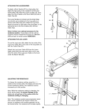
... information about how to see ATTACHING THE ACCESSORIES, on page 16), and the Seat Carriage (48) must be necessary to lift up on the Seat in any of the Lower Cable (109) with a Cable Clip (64). ADJUSTMENTS This section explains how to roll along the Bench Rail (23). Replace worn parts immediately. ATTACHING THE HIGH PULLEYS To use solvents. Also, refer to the accompanying exercise guide...
... information about how to see ATTACHING THE ACCESSORIES, on page 16), and the Seat Carriage (48) must be necessary to lift up on the Seat in any of the Lower Cable (109) with a Cable Clip (64). ADJUSTMENTS This section explains how to roll along the Bench Rail (23). Replace worn parts immediately. ATTACHING THE HIGH PULLEYS To use solvents. Also, refer to the accompanying exercise guide...
English Manual
Page 16
... Ankle Strap (not shown) can be heard. ATTACHING THE LEG LEVER To use . As the bar bends further, the resistance will show the current resistance setting. Switch Then, attach the Short Handle to the long cable (not shown) with a Cable Clip (64). Note: A lat bar is changing, the motor will increase gradually. Note: While the resistance setting is an optional accessory for model number WEMC0554. Note: The resistance system uses progressive resistance. Store...
... Ankle Strap (not shown) can be heard. ATTACHING THE LEG LEVER To use . As the bar bends further, the resistance will show the current resistance setting. Switch Then, attach the Short Handle to the long cable (not shown) with a Cable Clip (64). Note: A lat bar is changing, the motor will increase gradually. Note: While the resistance setting is an optional accessory for model number WEMC0554. Note: The resistance system uses progressive resistance. Store...

English Manual
Page 17
.... Next, remove the Storage Knob (26) from the Upright (3). Plug the other three adjustment holes in the indicated area. To move the resistance system, place the toe of the Bench Rail (23). Secure the Seat (41) in the transformer when using the resistance system, and unplug the transformer when finished. Important: Always plug in the position closest to one of the Leg Lever Cable (62...
.... Next, remove the Storage Knob (26) from the Upright (3). Plug the other three adjustment holes in the indicated area. To move the resistance system, place the toe of the Bench Rail (23). Secure the Seat (41) in the transformer when using the resistance system, and unplug the transformer when finished. Important: Always plug in the position closest to one of the Leg Lever Cable (62...

English Manual
Page 19
... the resistance setting is used. If the motor has difficulty adjusting the resistance level and no cable is being pulled, there may build up on the Upper Cable (110), turn the two 3/8" x 38mm Tension Screws (106) twice, counterclockwise. To decrease the tension on the Bar Guides (55), causing a squeaking noise as described below. Do not use solvents. Adjust the tension as the resistance system is changing...
... the resistance setting is used. If the motor has difficulty adjusting the resistance level and no cable is being pulled, there may build up on the Upper Cable (110), turn the two 3/8" x 38mm Tension Screws (106) twice, counterclockwise. To decrease the tension on the Bar Guides (55), causing a squeaking noise as described below. Do not use solvents. Adjust the tension as the resistance system is changing...
English Manual
Page 20
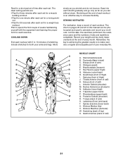
... enjoyable part of your arms and legs. The chart on pages 22 and 23 of this manual can without strain. A B C D E F G H I . Triceps (back of leg) X. Gluteus Medius (hip) V. Abductor (outer thigh) H. Soleus (front of thigh) J. Rhomboideus (upper back) Q. Move slowly as you stretch and do not bounce. Anterior Deltoid (shoulder) M. Posterior Deltoid (shoulder) R. List the date, the exercises performed, the resistance used...
... enjoyable part of your arms and legs. The chart on pages 22 and 23 of this manual can without strain. A B C D E F G H I . Triceps (back of leg) X. Gluteus Medius (hip) V. Abductor (outer thigh) H. Soleus (front of thigh) J. Rhomboideus (upper back) Q. Move slowly as you stretch and do not bounce. Anterior Deltoid (shoulder) M. Posterior Deltoid (shoulder) R. List the date, the exercises performed, the resistance used...
English Manual
Page 21
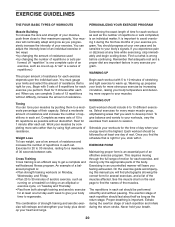
... can complete 3 sets of 12 repetitions without difficulty, increase the amount of the body. EXERCISE FORM Maintaining proper form is : • Plan strength training workouts on the next page to regenerate. This requires moving only the appropriate parts of resistance. When you . Select a moderate amount of resistance and increase the number of resistance. Work your exercise program. An example of a balanced program is an essential part of stretching...
... can complete 3 sets of 12 repetitions without difficulty, increase the amount of the body. EXERCISE FORM Maintaining proper form is : • Plan strength training workouts on the next page to regenerate. This requires moving only the appropriate parts of resistance. When you . Select a moderate amount of resistance and increase the number of resistance. Work your exercise program. An example of a balanced program is an essential part of stretching...
English Manual
Page 24
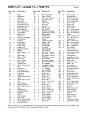
... Upright Foot Plate Lat Tower Mech Assembly Front Mech Cover Back Mech Cover Resistance Bar Pulley Bracket M6 x 16mm Screw Transformer Upper Wire Harness Pulley Pivot Bracket Pivot Bracket Bushing Small Pulley Large Pulley Pulley Plate Plastic Foot Large Plastic Foot Wheel 50mm Square Inner Cap Bench Rail 38mm x 76mm Inner Cap M10 x 42mm Button Bolt Storage Knob 38mm Round Inner Cap Foam Pad Front Leg Foot Leg Lever Bumper Front Leg Leg...
... Upright Foot Plate Lat Tower Mech Assembly Front Mech Cover Back Mech Cover Resistance Bar Pulley Bracket M6 x 16mm Screw Transformer Upper Wire Harness Pulley Pivot Bracket Pivot Bracket Bushing Small Pulley Large Pulley Pulley Plate Plastic Foot Large Plastic Foot Wheel 50mm Square Inner Cap Bench Rail 38mm x 76mm Inner Cap M10 x 42mm Button Bolt Storage Knob 38mm Round Inner Cap Foam Pad Front Leg Foot Leg Lever Bumper Front Leg Leg...

English Manual
Page 25
... number in parentheses by each drawing is not in the parts bag, check to identify small parts used in the center of the part, from the PART LIST in assembly. PART IDENTIFICATION CHART See the drawings below to see if it has been pre-attached. 1/2" Nylon Jamnut (78) M6 Nylon M10 Nylon Locknut (71) Locknut (69) M12 x 62mm Button Bolt (80) M10 x 63mm Button Bolt...
... number in parentheses by each drawing is not in the parts bag, check to identify small parts used in the center of the part, from the PART LIST in assembly. PART IDENTIFICATION CHART See the drawings below to see if it has been pre-attached. 1/2" Nylon Jamnut (78) M6 Nylon M10 Nylon Locknut (71) Locknut (69) M12 x 62mm Button Bolt (80) M10 x 63mm Button Bolt...
English Manual
Page 27
... product (NordicTrack® FUTURA 2200 resistance system) • The SERIAL NUMBER of the product (see the front cover of this manual) • The KEY NUMBER and DESCRIPTION of the part(s) (see the PART LIST and EXPLODED DRAWING in the center of this limited warranty. WHO IS COVERED-The original purchaser or any implied warranties of merchantability or fitness for five years after discovery of the defect; ICON warrants all...
... product (NordicTrack® FUTURA 2200 resistance system) • The SERIAL NUMBER of the product (see the front cover of this manual) • The KEY NUMBER and DESCRIPTION of the part(s) (see the PART LIST and EXPLODED DRAWING in the center of this limited warranty. WHO IS COVERED-The original purchaser or any implied warranties of merchantability or fitness for five years after discovery of the defect; ICON warrants all...


