
English Manual
Page 2
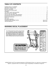
...of Google Inc. 2 App store is a trademark of this manual and request a free replacement decal. Apply the decal in the U.S. NORDICTRACK and IFIT are registered trademarks of the warning decals. Google Maps is missing or illegible, call the telephone number on the front cover ...WARNING DECAL PLACEMENT 2 IMPORTANT PRECAUTIONS 3 BEFORE YOU BEGIN 7 PART IDENTIFICATION CHART 8 ASSEMBLY 9 THE CHEST HEART RATE MONITOR 18 HOW TO USE THE TREADMILL 19 HOW TO FOLD AND MOVE THE TREADMILL 33 MAINTENANCE AND TROUBLESHOOTING 34 EXERCISE GUIDELINES 37 PART LIST 38 EXPLODED DRAWING 40 ORDERING ...
...of Google Inc. 2 App store is a trademark of this manual and request a free replacement decal. Apply the decal in the U.S. NORDICTRACK and IFIT are registered trademarks of the warning decals. Google Maps is missing or illegible, call the telephone number on the front cover ...WARNING DECAL PLACEMENT 2 IMPORTANT PRECAUTIONS 3 BEFORE YOU BEGIN 7 PART IDENTIFICATION CHART 8 ASSEMBLY 9 THE CHEST HEART RATE MONITOR 18 HOW TO USE THE TREADMILL 19 HOW TO FOLD AND MOVE THE TREADMILL 33 MAINTENANCE AND TROUBLESHOOTING 34 EXERCISE GUIDELINES 37 PART LIST 38 EXPLODED DRAWING 40 ORDERING ...
English Manual
Page 4
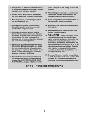
... speed. 23. Never leave the treadmill unattended while it is properly assembled. (See ASSEMBLY on page 9 and HOW TO FOLD AND MOVE THE TREADMILL on page 33.) You must be performed by an authorized service representative. Always remove the key, press the power switch into any opening on the treadmill, the noise level of high...
... speed. 23. Never leave the treadmill unattended while it is properly assembled. (See ASSEMBLY on page 9 and HOW TO FOLD AND MOVE THE TREADMILL on page 33.) You must be performed by an authorized service representative. Always remove the key, press the power switch into any opening on the treadmill, the noise level of high...

English Manual
Page 8
... below to see whether it is preattached. The number in the hardware kit, check to identify small parts used for assembly. The number following the key number is the quantity used for assembly. PART IDENTIFICATION CHART Use the drawings below each drawing is the key number of the part, from the PART...
... below to see whether it is preattached. The number in the hardware kit, check to identify small parts used for assembly. The number following the key number is the quantity used for assembly. PART IDENTIFICATION CHART Use the drawings below each drawing is the key number of the part, from the PART...

English Manual
Page 9
...register your warranty • saves you time if you ever need to contact Customer Care • allows us to www.nordictrackservice.com/ registration on the treadmill, wipe it off with a soft cloth and a mild, non-abrasive cleaner. • To identify small parts, see page 8. • Left... parts are marked "L" or "Left" and right parts are marked "R" or "Right." • Assembly requires the following tools: the included hex key one adjustable wrench one Phillips screwdriver To avoid damaging parts, do not have internet access, call Customer...
...register your warranty • saves you time if you ever need to contact Customer Care • allows us to www.nordictrackservice.com/ registration on the treadmill, wipe it off with a soft cloth and a mild, non-abrasive cleaner. • To identify small parts, see page 8. • Left... parts are marked "L" or "Left" and right parts are marked "R" or "Right." • Assembly requires the following tools: the included hex key one adjustable wrench one Phillips screwdriver To avoid damaging parts, do not have internet access, call Customer...

English Manual
Page 12
L K Remove and discard the four indicated screws (L). Set the console assembly (K) face down on the right side. Then, remove the Pulse Crossbar (80). 80 L L 12 8. Then, remove and discard the two indicated screws (J). 8 2 8 J 74 74 2 G 83 8 J I ) ...as shown. Position the wires in step 5 and two 5/16" Star Washers (8); Attach the two Handrails (74) to avoid scratching the console 9 assembly. Be careful not to pinch the Upright Wire (83) or the fan wire (G) on a soft surface to the Right and Left Uprights (84, 91) with...
L K Remove and discard the four indicated screws (L). Set the console assembly (K) face down on the right side. Then, remove the Pulse Crossbar (80). 80 L L 12 8. Then, remove and discard the two indicated screws (J). 8 2 8 J 74 74 2 G 83 8 J I ) ...as shown. Position the wires in step 5 and two 5/16" Star Washers (8); Attach the two Handrails (74) to avoid scratching the console 9 assembly. Be careful not to pinch the Upright Wire (83) or the fan wire (G) on a soft surface to the Right and Left Uprights (84, 91) with...

English Manual
Page 13
... not use power tools, and do not, turn one connector and try again. Attach the Pulse Crossbar with two of a second person, hold the console assembly (K) near the Handrails (74). IF YOU DO NOT CONNECT THE CONNECTORS PROPERLY, THE CONSOLE MAY BECOME DAMAGED WHEN YOU TURN ON THE POWER. With the...
... not use power tools, and do not, turn one connector and try again. Attach the Pulse Crossbar with two of a second person, hold the console assembly (K) near the Handrails (74). IF YOU DO NOT CONNECT THE CONNECTORS PROPERLY, THE CONSOLE MAY BECOME DAMAGED WHEN YOU TURN ON THE POWER. With the...

English Manual
Page 14
... to the Handrails (74) with the hardware. Insert the wires (M) into the Pulse Crossbar (80), and then tighten them . M 84 27 14. Attach the console assembly (K) to pinch the wires (M). 74 M 8 2 K 74 8 2 13. Start eight #8 x 3/4" Truss Head Screws (24) into the top of the Right Upright (84). 13 Locate the Wire...
... to the Handrails (74) with the hardware. Insert the wires (M) into the Pulse Crossbar (80), and then tighten them . M 84 27 14. Attach the console assembly (K) to pinch the wires (M). 74 M 8 2 K 74 8 2 13. Start eight #8 x 3/4" Truss Head Screws (24) into the top of the Right Upright (84). 13 Locate the Wire...

English Manual
Page 15
Next, slide the Left Handrail Top and Bottom Covers forward against the console assembly (K) as shown. Set the Left Handrail Top Cover (73) on the Frame (52) with the two 5/16" x 1 1/4" Screws (16) and two 5/16" Star Washers (8). 16 8 ...) as shown. Make sure that the "This side toward belt" sticker (O) is completed. Have a second person hold the Frame until step 18 is facing the treadmill. Attach the Latch Crossbar (109) to the brackets (P) on the left Handrail, and the Left Handrail Top Cover. Attach the Right Handrail Top and Bottom...
Next, slide the Left Handrail Top and Bottom Covers forward against the console assembly (K) as shown. Set the Left Handrail Top Cover (73) on the Frame (52) with the two 5/16" x 1 1/4" Screws (16) and two 5/16" Star Washers (8). 16 8 ...) as shown. Make sure that the "This side toward belt" sticker (O) is completed. Have a second person hold the Frame until step 18 is facing the treadmill. Attach the Latch Crossbar (109) to the brackets (P) on the left Handrail, and the Left Handrail Top Cover. Attach the Right Handrail Top and Bottom...

English Manual
Page 17
... into place. 90 89 23 20 23 23 20 20. one of the hex keys is designed for use the treadmill. 19. IMPORTANT: The Tablet Holder (121) is used to the console assembly (K) with most full-size tablets. If there are properly tightened before you use with four M4 x 16mm Screws (108... included hex keys in the Tablet Holder. 20 Start First 108 121 108 K 21. To protect the floor or carpet, place a mat under the treadmill. Note: Extra parts may be included. 17 Note: Start the two top Screws first, and then start the two bottom Screws. Be careful not...
... into place. 90 89 23 20 23 23 20 20. one of the hex keys is designed for use the treadmill. 19. IMPORTANT: The Tablet Holder (121) is used to the console assembly (K) with most full-size tablets. If there are properly tightened before you use with four M4 x 16mm Screws (108... included hex keys in the Tablet Holder. 20 Start First 108 121 108 K 21. To protect the floor or carpet, place a mat under the treadmill. Note: Extra parts may be included. 17 Note: Start the two top Screws first, and then start the two bottom Screws. Be careful not...


