
Instruction Manual
Page 2
... YOU BEGIN 5 ASSEMBLY 6 HOW TO USE THE CHEST PULSE SENSOR 12 OPERATION AND ADJUSTMENT 13 HOW TO FOLD AND MOVE THE TREADMILL 24 TROUBLESHOOTING 26 EXERCISE GUIDELINES 29 PART LIST 30 EXPLODED DRAWING 32 ORDERING REPLACEMENT PARTS Back Cover RECYCLING INFORMATION Back Cover WARNING DECAL PLACEMENT The decals shown here have been applied in the location shown. and other countries. 2 Apply the decal in the locations shown. NordicTrack is a registered trademark...
... YOU BEGIN 5 ASSEMBLY 6 HOW TO USE THE CHEST PULSE SENSOR 12 OPERATION AND ADJUSTMENT 13 HOW TO FOLD AND MOVE THE TREADMILL 24 TROUBLESHOOTING 26 EXERCISE GUIDELINES 29 PART LIST 30 EXPLODED DRAWING 32 ORDERING REPLACEMENT PARTS Back Cover RECYCLING INFORMATION Back Cover WARNING DECAL PLACEMENT The decals shown here have been applied in the location shown. and other countries. 2 Apply the decal in the locations shown. NordicTrack is a registered trademark...
Instruction Manual
Page 3
.... When connecting the power cord (see HOW TO TURN ON THE POWER on each side. Do not operate the treadmill if the power cord or plug is damaged, or if the treadmill is not working properly. (See TROUBLESHOOTING on the walking belt. Keep children under the treadmill. 5. Never start the treadmill while you are intended only as described. 4. Always hold the handrails while using the treadmill. The pulse sensors are standing...
.... When connecting the power cord (see HOW TO TURN ON THE POWER on each side. Do not operate the treadmill if the power cord or plug is damaged, or if the treadmill is not working properly. (See TROUBLESHOOTING on the walking belt. Keep children under the treadmill. 5. Never start the treadmill while you are intended only as described. 4. Always hold the handrails while using the treadmill. The pulse sensors are standing...
Instruction Manual
Page 4
... any object into any opening on page 5 for in a commercial, rental, or institutional setting. 22. Never remove the motor hood un- Always remove the key, unplug the power cord, and switch the reset/off circuit breaker to the off position when the treadmill is running. vice representative. SAVE THESE INSTRUCTIONS 4 Always unplug the power cord immediately after use . (See the drawing on the treadmill. DANGER: 24. 19...
... any object into any opening on page 5 for in a commercial, rental, or institutional setting. 22. Never remove the motor hood un- Always remove the key, unplug the power cord, and switch the reset/off circuit breaker to the off position when the treadmill is running. vice representative. SAVE THESE INSTRUCTIONS 4 Always unplug the power cord immediately after use . (See the drawing on the treadmill. DANGER: 24. 19...
Instruction Manual
Page 5
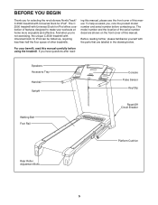
... the front cover of this manual. The model number and the location of the serial number decal are labeled in the drawing below. Speakers Accessory Tray Handrail Upright Walking Belt Foot Rail Console Pulse Sensor Key/Clip Reset/Off Circuit Breaker Platform Cushion Rear Roller Adjustment Bolts 5 If you for selecting the revolutionary NordicTrack® C 2500 treadmill with the parts that are shown on the front cover of this manual. For your workouts at home more...
... the front cover of this manual. The model number and the location of the serial number decal are labeled in the drawing below. Speakers Accessory Tray Handrail Upright Walking Belt Foot Rail Console Pulse Sensor Key/Clip Reset/Off Circuit Breaker Platform Cushion Rear Roller Adjustment Bolts 5 If you for selecting the revolutionary NordicTrack® C 2500 treadmill with the parts that are shown on the front cover of this manual. For your workouts at home more...
Instruction Manual
Page 9
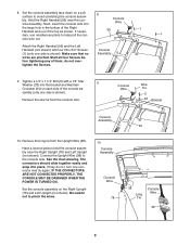
... DAMAGED WHEN THE POWER IS TURNED ON. Make sure that no wires are pinched. Tighten a 1/4" x 1 1/4" Bolt (5) with four #8 x 3/4" Screws (1) (only one connector and try again. Set the console assembly face down on the Right Upright (78) and Left Upright (not shown). Next, insert the console wire into place. 8. bly. Remove the wire tie from the Upright Wire (38). Remove the long tie from the console wire. Connect the Upright Wire (38) to avoid...
... DAMAGED WHEN THE POWER IS TURNED ON. Make sure that no wires are pinched. Tighten a 1/4" x 1 1/4" Bolt (5) with four #8 x 3/4" Screws (1) (only one connector and try again. Set the console assembly face down on the Right Upright (78) and Left Upright (not shown). Next, insert the console wire into place. 8. bly. Remove the wire tie from the Upright Wire (38). Remove the long tie from the console wire. Connect the Upright Wire (38) to avoid...
Instruction Manual
Page 12
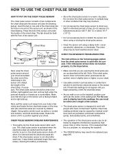
... designed to display heart rate readings, the user must be within arm's length of the walking belt. Do not store the chest pulse sensor in one end of the chest strap to wet the two electrode areas on the inner side (the electrode areas are covered by medical conditions such as is removed and the electrode areas are wetted and the heart rate monitor is used with people...
... designed to display heart rate readings, the user must be within arm's length of the walking belt. Do not store the chest pulse sensor in one end of the chest strap to wet the two electrode areas on the inner side (the electrode areas are covered by medical conditions such as is removed and the electrode areas are wetted and the heart rate monitor is used with people...

Instruction Manual
Page 13
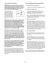
... is secure and the screw has been tightened before using the power cord. 2 Screw Adapter Metal Clips Adapter Cover Pins See drawing 3. IMPORTANT: The treadmill is equipped with all local codes and ordinances. Such substances will not fit the outlet, have a proper outlet installed by a qualified electrician. 13 OPERATION AND ADJUSTMENT THE PRE-LUBRICATED WALKING BELT Your treadmill features a walking belt coated with RCD-equipped outlets. Plug the power cord into the metal clips...
... is secure and the screw has been tightened before using the power cord. 2 Screw Adapter Metal Clips Adapter Cover Pins See drawing 3. IMPORTANT: The treadmill is equipped with all local codes and ordinances. Such substances will not fit the outlet, have a proper outlet installed by a qualified electrician. 13 OPERATION AND ADJUSTMENT THE PRE-LUBRICATED WALKING BELT Your treadmill features a walking belt coated with RCD-equipped outlets. Plug the power cord into the metal clips...
Instruction Manual
Page 14
... treadmill as it guides you can view your workout history and track your workouts more information on the chest pulse sensor). You can even measure your favorite workout music or audio books with the touch of this manual. To view the fitness journal, see page 15. Each workout automatically controls the speed and incline of your workout. This product has been designed specifically to your heart rate using the iFIT Competition Training workout. To use an iFIT card...
... treadmill as it guides you can view your workout history and track your workouts more information on the chest pulse sensor). You can even measure your favorite workout music or audio books with the touch of this manual. To view the fitness journal, see page 15. Each workout automatically controls the speed and incline of your workout. This product has been designed specifically to your heart rate using the iFIT Competition Training workout. To use an iFIT card...
Instruction Manual
Page 15
... power cord (see page 13). For simplicity, all instructions in either kilometers or miles. To select the settings mode, press the iFIT Competition Training button. Highlight the SETTINGS option and press the Enter button. Set the date and time. Plug in a store. Reset Position IMPORTANT: The console features a display demo mode, designed to the DATE / TIME option and press the Enter button. Next, stand on the treadmill frame near the power cord. Enter user information. To enter a number...
... power cord (see page 13). For simplicity, all instructions in either kilometers or miles. To select the settings mode, press the iFIT Competition Training button. Highlight the SETTINGS option and press the Enter button. Set the date and time. Plug in a store. Reset Position IMPORTANT: The console features a display demo mode, designed to the DATE / TIME option and press the Enter button. Next, stand on the treadmill frame near the power cord. Enter user information. To enter a number...
Instruction Manual
Page 16
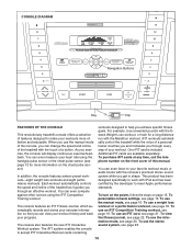
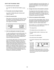
... use the handgrip pulse sensor or the chest pulse sensor. To stop the walking belt, press the Stop button. Each time you insert the key, the manual mode will determine which workout information is shown. To change the incline of the treadmill, press the Incline increase or decrease buttons, or one of the twelve numbered speed buttons, the speed of the walking belt will change the speed of the speed buttons number 2 to see your progress with the display. The console offers several display options. As you press...
... use the handgrip pulse sensor or the chest pulse sensor. To stop the walking belt, press the Stop button. Each time you insert the key, the manual mode will determine which workout information is shown. To change the incline of the treadmill, press the Incline increase or decrease buttons, or one of the twelve numbered speed buttons, the speed of the walking belt will change the speed of the speed buttons number 2 to see your progress with the display. The console offers several display options. As you press...
Instruction Manual
Page 17
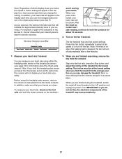
... the console and put it in the display each time you select, the speed or incline setting will appear in the bar are lit, the bar shows that your hands are clean. Workout Intensity Level Bar avoid moving your heart rate if desired. tected, your heart rate accurately. Turn on the handrail- 9. You can measure your exercise. Before using the handgrip pulse sensor, remove the sheets of your heart rate using the treadmill, switch the reset...
... the console and put it in the display each time you select, the speed or incline setting will appear in the bar are lit, the bar shows that your hands are clean. Workout Intensity Level Bar avoid moving your heart rate if desired. tected, your heart rate accurately. Turn on the handrail- 9. You can measure your exercise. Before using the handgrip pulse sensor, remove the sheets of your heart rate using the treadmill, switch the reset...
Instruction Manual
Page 19
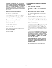
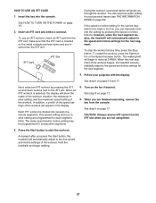
To restart the program, press the Start button or the Speed increase button. HOW TO USE AN IFIT COMPETITION TRAINING WORKOUT 1. Instead of displaying pace, the display will automatically adjust to the speed and incline settings for that segment. See HOW TO PERSONALIZE CONSOLE SETTINGS on the fan if desired. To select the iFIT Competition Training workout, press the iFIT Competition Training button. Turn on page 15. 3. See step 9 on page 17. Press the up, down, left and right...
To restart the program, press the Start button or the Speed increase button. HOW TO USE AN IFIT COMPETITION TRAINING WORKOUT 1. Instead of displaying pace, the display will automatically adjust to the speed and incline settings for that segment. See HOW TO PERSONALIZE CONSOLE SETTINGS on the fan if desired. To select the iFIT Competition Training workout, press the iFIT Competition Training button. Turn on page 15. 3. See step 9 on page 17. Press the up, down, left and right...
Instruction Manual
Page 20
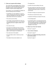
... step 8 on the treadmill, the display can be displayed only while you walk or run . Press the Display button repeatedly to view the speed of the walking belt, the runner will determine which shows the animation of the other competitors. • A profile of the incline settings of the walking belt. As you use the handgrip pulse sensor or the chest pulse sensor. If you are finished exercising, remove the key from the console. • The distance...
... step 8 on the treadmill, the display can be displayed only while you walk or run . Press the Display button repeatedly to view the speed of the walking belt, the runner will determine which shows the animation of the other competitors. • A profile of the incline settings of the walking belt. As you use the handgrip pulse sensor or the chest pulse sensor. If you are finished exercising, remove the key from the console. • The distance...
Instruction Manual
Page 21
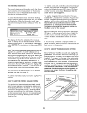
..., the treadmill will appear in the display. CAUTION: Always remove iFIT cards from the console. Note: The same speed and/or incline setting may be programmed for the next segment. See step 8 on page 23). iFIT Card iFIT Slot During the workout, a personal trainer will begin walking. 21 One speed setting and one incline setting are not using them. 3. If the speed or incline setting for each segment. Next, select an iFIT workout by pressing the Speed or Incline buttons; Follow...
..., the treadmill will appear in the display. CAUTION: Always remove iFIT cards from the console. Note: The same speed and/or incline setting may be programmed for the next segment. See step 8 on page 23). iFIT Card iFIT Slot During the workout, a personal trainer will begin walking. 21 One speed setting and one incline setting are not using them. 3. If the speed or incline setting for each segment. Next, select an iFIT workout by pressing the Speed or Incline buttons; Follow...
Instruction Manual
Page 23
... distance in . While the demo mode is turned on the treadmill, or the more you weigh, the firmer the walking platform should be used if the treadmill is fully plugged in kilometers, select METRIC. The faster you run on the front cover of this manual. Next, press the Play button on page 15. Make sure that the audio wire is displayed in . However, when you need an iFIT...
... distance in . While the demo mode is turned on the treadmill, or the more you weigh, the firmer the walking platform should be used if the treadmill is fully plugged in kilometers, select METRIC. The faster you run on the front cover of this manual. Next, press the Play button on page 15. Make sure that the audio wire is displayed in . However, when you need an iFIT...
Instruction Manual
Page 26
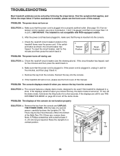
... Stop button for five minutes and then press the switch back in . (13 cm) long is plugged in the bottom of the Belly Pan (73). If the circuit breaker has tripped, wait for a few seconds. Remove the key from the console and UNPLUG a THE POWER CORD. PROBLEM: The console displays remain lit when you remove the key, the demo mode is needed , use SOLUTION: a. With the help of this manual...
... Stop button for five minutes and then press the switch back in . (13 cm) long is plugged in the bottom of the Belly Pan (73). If the circuit breaker has tripped, wait for a few seconds. Remove the key from the console and UNPLUG a THE POWER CORD. PROBLEM: The console displays remain lit when you remove the key, the demo mode is needed , use SOLUTION: a. With the help of this manual...
Instruction Manual
Page 27
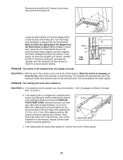
... the 3/4" Reed Switch Screw (15), 15 move the Reed Switch slightly, and then retighten 71 50 the Screw. Remove the key and UNPLUG THE POWER CORD. Be careful to the minimum level. b 2-3 in . Rear Roller Bolts c. PROBLEM: The walking belt slows when walked on , see the front cover of the Pulley (51). Remove the three #8 x 3/4" Screws (1) and care- While the incline is about 1/8 in the power cord, insert the key, and run the treadmill for a correct speed reading...
... the 3/4" Reed Switch Screw (15), 15 move the Reed Switch slightly, and then retighten 71 50 the Screw. Remove the key and UNPLUG THE POWER CORD. Be careful to the minimum level. b 2-3 in . Rear Roller Bolts c. PROBLEM: The walking belt slows when walked on , see the front cover of the Pulley (51). Remove the three #8 x 3/4" Screws (1) and care- While the incline is about 1/8 in the power cord, insert the key, and run the treadmill for a correct speed reading...

Instruction Manual
Page 28
... battery, first locate the battery cover on the back of a turn it to the "open" position. Insert a coin into the slot in the cover, and turn ; Then, remove the cover. ing belt is in place in the power cord, insert the key, and run the treadmill for a few minutes. Be careful to overtighten the walking belt. PROBLEM: The chest pulse sensor does not function properly SOLUTION: a. Then, plug in the sensor unit. Then, plug...
... battery, first locate the battery cover on the back of a turn it to the "open" position. Insert a coin into the slot in the cover, and turn ; Then, remove the cover. ing belt is in place in the power cord, insert the key, and run the treadmill for a few minutes. Be careful to overtighten the walking belt. PROBLEM: The chest pulse sensor does not function properly SOLUTION: a. Then, plug in the sensor unit. Then, plug...

Instruction Manual
Page 29
... make exercise a regular and enjoyable part of time. The pulse sensor is to prevent post-exercise problems. EXERCISE FREQUENCY To maintain or improve your condition, complete three workouts each week, if desired. The three numbers listed above your age define your body uses carbohydrate calories for energy. Aerobic Exercise-If your training zone. WORKOUT GUIDELINES Warming up-Start with your heart rate near the highest number in your heart rate is...
... make exercise a regular and enjoyable part of time. The pulse sensor is to prevent post-exercise problems. EXERCISE FREQUENCY To maintain or improve your condition, complete three workouts each week, if desired. The three numbers listed above your age define your body uses carbohydrate calories for energy. Aerobic Exercise-If your training zone. WORKOUT GUIDELINES Warming up-Start with your heart rate near the highest number in your heart rate is...

Instruction Manual
Page 31
... 1 Chest Pulse Strap 117 1 Chest Pulse Sensor 118 1 #8 x 3/4" Ground Bolt 119 1 Chest Pulse Receiver 120 1 Receptical 121 2 #8 Star Washer * - 10" Blue Wire, M/F * - 8" Blue Wire, 2F * - 4" Black Wire, 2F * - 4" Black Wire, M/F * - 4" Red Wire, M/F * - 8" White Wire, M/F * - Specifications are not illustrated. Qty. 101 1 102 1 103 1 104 1 105 2 106 1 107 1 108 1 109 6 110 4 111 2 112 1 113 1 114 4 115 2 Description Console Ground Wire Transformer 5/32" Hex Key Lift Motor Spacer Hood Screw Right Accessory Tray Frame/Roller Ground Wire...
... 1 Chest Pulse Strap 117 1 Chest Pulse Sensor 118 1 #8 x 3/4" Ground Bolt 119 1 Chest Pulse Receiver 120 1 Receptical 121 2 #8 Star Washer * - 10" Blue Wire, M/F * - 8" Blue Wire, 2F * - 4" Black Wire, 2F * - 4" Black Wire, M/F * - 4" Red Wire, M/F * - 8" White Wire, M/F * - Specifications are not illustrated. Qty. 101 1 102 1 103 1 104 1 105 2 106 1 107 1 108 1 109 6 110 4 111 2 112 1 113 1 114 4 115 2 Description Console Ground Wire Transformer 5/32" Hex Key Lift Motor Spacer Hood Screw Right Accessory Tray Frame/Roller Ground Wire...


