

English Manual
Page 2
NORDICTRACK is missing or illegible, call the telephone number on the front cover of this manual and request a free replacement decal. TABLE OF CONTENTS WARNING DECAL PLACEMENT 2 IMPORTANT PRECAUTIONS 3 BEFORE YOU BEGIN 7 PART IDENTIFICATION CHART 8 ASSEMBLY 9 THE CHEST HEART RATE MONITOR 20 OPERATION AND ADJUSTMENT 21 HOW TO FOLD AND MOVE THE TREADMILL 30...
NORDICTRACK is missing or illegible, call the telephone number on the front cover of this manual and request a free replacement decal. TABLE OF CONTENTS WARNING DECAL PLACEMENT 2 IMPORTANT PRECAUTIONS 3 BEFORE YOU BEGIN 7 PART IDENTIFICATION CHART 8 ASSEMBLY 9 THE CHEST HEART RATE MONITOR 20 OPERATION AND ADJUSTMENT 21 HOW TO FOLD AND MOVE THE TREADMILL 30...

English Manual
Page 4
...opening on page 30.) You must be performed by an authorized service representative. Never remove the motor hood unless instructed to move the treadmill until it is holding the frame securely in general. 21. Inspect and properly tighten all parts of heart rate readings. Servicing other ...20 kg) to do so by an authorized ser- The heart rate monitor is properly assembled. (See ASSEMBLY on page 9 and HOW TO FOLD AND MOVE THE TREADMILL on the treadmill. 26. Never leave the treadmill unattended while it is intended only as an exercise aid in determining heart rate trends in...
...opening on page 30.) You must be performed by an authorized service representative. Never remove the motor hood unless instructed to move the treadmill until it is holding the frame securely in general. 21. Inspect and properly tighten all parts of heart rate readings. Servicing other ...20 kg) to do so by an authorized ser- The heart rate monitor is properly assembled. (See ASSEMBLY on page 9 and HOW TO FOLD AND MOVE THE TREADMILL on the treadmill. 26. Never leave the treadmill unattended while it is intended only as an exercise aid in determining heart rate trends in...

English Manual
Page 8
...;-6 8 The number following the key number is preattached. Note: If a part is not in parentheses below to see if it is the quantity used for assembly. The number in the hardware kit, check to identify small parts used for...
...;-6 8 The number following the key number is preattached. Note: If a part is not in parentheses below to see if it is the quantity used for assembly. The number in the hardware kit, check to identify small parts used for...

English Manual
Page 9
...all assembly steps. •• After shipping, there may be an oily substance on the exterior of this manual) and register your warranty •• saves you time if you ever need to contact Customer Care •• allows us to www.nordictrackservice.com/ registration on the treadmill, ... and right parts are marked “"R”" or “"Right.”" •• To identify small parts, see the front cover of the treadmill. This is an oily substance on your computer and register 1 your product. •• activates your product. 9 Do not dispose of the ...
...all assembly steps. •• After shipping, there may be an oily substance on the exterior of this manual) and register your warranty •• saves you time if you ever need to contact Customer Care •• allows us to www.nordictrackservice.com/ registration on the treadmill, ... and right parts are marked “"R”" or “"Right.”" •• To identify small parts, see the front cover of the treadmill. This is an oily substance on your computer and register 1 your product. •• activates your product. 9 Do not dispose of the ...
English Manual
Page 14
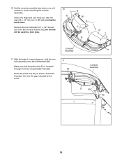
... down on a soft surface to avoid scratching the console assembly. Make sure that the pulse wire (D) is inserted through the three looped Cable Ties (99). Remove the four indicated 1/4" x 1/2" Screws (31) from the Console Frame (... wire (D) as shown, and insert the pulse wire into the gap indicated by the arrow. 11 99 31 Console Assembly D 99 86 14 With the help of a second person, hold the console assembly near the left Handrail (86). Attach the Right and Left Trays (27, 36) with eight #8 x 1/2" Screws (1). the Screws will...
... down on a soft surface to avoid scratching the console assembly. Make sure that the pulse wire (D) is inserted through the three looped Cable Ties (99). Remove the four indicated 1/4" x 1/2" Screws (31) from the Console Frame (... wire (D) as shown, and insert the pulse wire into the gap indicated by the arrow. 11 99 31 Console Assembly D 99 86 14 With the help of a second person, hold the console assembly near the left Handrail (86). Attach the Right and Left Trays (27, 36) with eight #8 x 1/2" Screws (1). the Screws will...

English Manual
Page 15
With the help of a second person, hold the console assembly near the right Handrail (86). 12 Make sure that you removed in step 10 and four 1/4" Star Washers (32). Route the Upright Wire (81) as ... 32 31 15 Be careful not to pinch any 13 wires. Console Assembly 99 86 99 81 13. Set the console assembly on the brackets on the Handrails (86). Attach the console assembly with the four 1/4" x 1/2" Screws (31) that the Upright Wire (81) is inserted through the two looped Cable Ties (99). 12...
With the help of a second person, hold the console assembly near the right Handrail (86). 12 Make sure that you removed in step 10 and four 1/4" Star Washers (32). Route the Upright Wire (81) as ... 32 31 15 Be careful not to pinch any 13 wires. Console Assembly 99 86 99 81 13. Set the console assembly on the brackets on the Handrails (86). Attach the console assembly with the four 1/4" x 1/2" Screws (31) that the Upright Wire (81) is inserted through the two looped Cable Ties (99). 12...

English Manual
Page 17
... H Note: You will need to tip the Console Base Back (104) so that the flange on the Console Base Back slides into the handrail assembly. Attach the Console Cover (105) with two #8 x 3/4" Screws (2). 17 Tighten the six 3/8" x 4" Screws (7). Also, the speaker wires (H) need to ...fit into the handrail assembly (I). I ). See the side view drawing. Slide the Console Base Back (104) upward to the handrail assem- 16 bly (I Flange 105 2 82 7 83 7...
... H Note: You will need to tip the Console Base Back (104) so that the flange on the Console Base Back slides into the handrail assembly. Attach the Console Cover (105) with two #8 x 3/4" Screws (2). 17 Tighten the six 3/8" x 4" Screws (7). Also, the speaker wires (H) need to ...fit into the handrail assembly (I). I ). See the side view drawing. Slide the Console Base Back (104) upward to the handrail assem- 16 bly (I Flange 105 2 82 7 83 7...

English Manual
Page 18
... them. 11 4 90 41 4 11 89 19. Note: If assembled on the Frame (56) with the four 5/16" x 3/4" Screws (4) that the “"This side toward belt”" sticker (J) is completed. Raise the Frame (56) to the brackets on a smooth surface, the treadmill may roll forward during this step. Make sure that you...
... them. 11 4 90 41 4 11 89 19. Note: If assembled on the Frame (56) with the four 5/16" x 3/4" Screws (4) that the “"This side toward belt”" sticker (J) is completed. Raise the Frame (56) to the brackets on a smooth surface, the treadmill may roll forward during this step. Make sure that you...


