
Uk Manual
Page 2
... at actual size. Apply the decal in the location shown. TABLE OF CONTENTS WARNING DECAL PLACEMENT 2 IMPORTANT PRECAUTIONS 3 BEFORE YOU BEGIN 5 PART IDENTIFICATION CHART 6 ASSEMBLY 7 HOW TO USE THE TREADMILL 16 HOW TO FOLD AND MOVE THE TREADMILL 22 MAINTENANCE AND TROUBLESHOOTING 23 EXERCISE GUIDELINES 26 PART LIST 27 EXPLODED DRAWING 28 ORDERING REPLACEMENT PARTS Back Cover RECYCLING INFORMATION Back Cover WARNING DECAL PLACEMENT This drawing shows the locations of ICON IP...
... at actual size. Apply the decal in the location shown. TABLE OF CONTENTS WARNING DECAL PLACEMENT 2 IMPORTANT PRECAUTIONS 3 BEFORE YOU BEGIN 5 PART IDENTIFICATION CHART 6 ASSEMBLY 7 HOW TO USE THE TREADMILL 16 HOW TO FOLD AND MOVE THE TREADMILL 22 MAINTENANCE AND TROUBLESHOOTING 23 EXERCISE GUIDELINES 26 PART LIST 27 EXPLODED DRAWING 28 ORDERING REPLACEMENT PARTS Back Cover RECYCLING INFORMATION Back Cover WARNING DECAL PLACEMENT This drawing shows the locations of ICON IP...
Uk Manual
Page 3
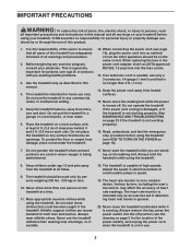
... turned off position (see page 16), plug the power cord into an earthed circuit. The treadmill should be used or where oxygen is intended for personal injury or property damage sus- Never move the walking belt while the power is the responsibility of the owner to avoid sudden jumps in small increments to ensure that blocks air openings. Various factors, including the user...
... turned off position (see page 16), plug the power cord into an earthed circuit. The treadmill should be used or where oxygen is intended for personal injury or property damage sus- Never move the walking belt while the power is the responsibility of the owner to avoid sudden jumps in small increments to ensure that blocks air openings. Various factors, including the user...
Uk Manual
Page 4
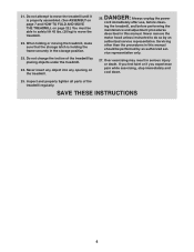
Do not change the incline of the treadmill regularly. Always unplug the power cord immediately after use, before performing the maintenance and adjustment procedures described in the storage position. 23. vice representative only. 27. Inspect and properly tighten all parts of the treadmill by an authorized ser- Do not attempt to move the treadmill. 22. DANGER: 26. Never remove the motor hood unless instructed to move the treadmill until it is...
Do not change the incline of the treadmill regularly. Always unplug the power cord immediately after use, before performing the maintenance and adjustment procedures described in the storage position. 23. vice representative only. 27. Inspect and properly tighten all parts of the treadmill by an authorized ser- Do not attempt to move the treadmill. 22. DANGER: 26. Never remove the motor hood unless instructed to move the treadmill until it is...
Uk Manual
Page 5
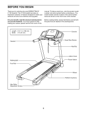
... model number and serial number before you use the treadmill. The model number and the location of the serial number decal are shown on the front cover of this Before reading further, please familiarize yourself with the parts that are labeled in . (185 cm) Width: 3 ft. (91 cm) Handrail Console Heart Rate Monitor Key/Clip Walking Belt Foot Rail Idler Roller Adjustment Screws Motor Hood Power Switch Wheel Platform Cushions 5 If you have questions after reading this manual...
... model number and serial number before you use the treadmill. The model number and the location of the serial number decal are shown on the front cover of this Before reading further, please familiarize yourself with the parts that are labeled in . (185 cm) Width: 3 ft. (91 cm) Handrail Console Heart Rate Monitor Key/Clip Walking Belt Foot Rail Idler Roller Adjustment Screws Motor Hood Power Switch Wheel Platform Cushions 5 If you have questions after reading this manual...

Uk Manual
Page 10
... to the Left Upright (not shown) in the same way. 6. Identify the Right Handrail (84). 6 Attach the Right Handrail (84) to avoid scratching the Console Base. 7 Remove and discard the two screws (A) from the Pulse Crossbar (93). Set the Console Base (64) face down on the left side. 28 11 81 84 90 7. Start both Screws, and then tighten them. A 64...
... to the Left Upright (not shown) in the same way. 6. Identify the Right Handrail (84). 6 Attach the Right Handrail (84) to avoid scratching the Console Base. 7 Remove and discard the two screws (A) from the Pulse Crossbar (93). Set the Console Base (64) face down on the left side. 28 11 81 84 90 7. Start both Screws, and then tighten them. A 64...

Uk Manual
Page 11
... snap into place. IF YOU DO NOT CONNECT THE CONNECTORS PROPERLY, THE CONSOLE MAY BECOME DAMAGED WHEN YOU TURN ON THE POWER. Start all four Screws, and then tighten them. 8 9 5 85 93 9 5 84 9. Orient the Pulse Crossbar (93) as shown. Then, remove the wire tie from the Upright Wire. 9 Console Assembly Console Wire 81 84 Wire Tie Console Wire 81 11 Connect the Upright Wire (81) to the Right and Left Handrails...
... snap into place. IF YOU DO NOT CONNECT THE CONNECTORS PROPERLY, THE CONSOLE MAY BECOME DAMAGED WHEN YOU TURN ON THE POWER. Start all four Screws, and then tighten them. 8 9 5 85 93 9 5 84 9. Orient the Pulse Crossbar (93) as shown. Then, remove the wire tie from the Upright Wire. 9 Console Assembly Console Wire 81 84 Wire Tie Console Wire 81 11 Connect the Upright Wire (81) to the Right and Left Handrails...

Uk Manual
Page 12
Insert the excess Upright Wire (81) into the Right Upright (90). Console Assembly 4 93 1 4 1 12 Make sure that no wires 10 are pinched. Set the console assembly on the Handrails (84, 85) with six #8 x 1/2" Screws (1). Attach the console assembly to the console assembly with four 1/4" x 1/2" Screws (4). Firmly tighten the four 1/4" x 1/2" Screws (4). Do not tighten the Screws yet. Start all 11 six Screws, and then tighten them. Attach the Pulse Crossbar (93) to the brackets on the...
Insert the excess Upright Wire (81) into the Right Upright (90). Console Assembly 4 93 1 4 1 12 Make sure that no wires 10 are pinched. Set the console assembly on the Handrails (84, 85) with six #8 x 1/2" Screws (1). Attach the console assembly to the console assembly with four 1/4" x 1/2" Screws (4). Firmly tighten the four 1/4" x 1/2" Screws (4). Do not tighten the Screws yet. Start all 11 six Screws, and then tighten them. Attach the Pulse Crossbar (93) to the brackets on the...

Uk Manual
Page 16
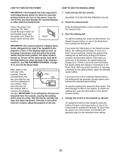
HOW TO USE THE TREADMILL HOW TO PLUG IN THE POWER CORD This product must be earthed. This product's power cord has an equipment-earthing conductor and an earthing plug. IMPORTANT: If the power cord is properly earthed. Do not modify the plug provided with the product-if it must be replaced with a manufacturer-recommended power cord. Plug the power cord into the socket on Treadmill DANGER: Improper connection of...
HOW TO USE THE TREADMILL HOW TO PLUG IN THE POWER CORD This product must be earthed. This product's power cord has an equipment-earthing conductor and an earthing plug. IMPORTANT: If the power cord is properly earthed. Do not modify the plug provided with the product-if it must be replaced with a manufacturer-recommended power cord. Plug the power cord into the socket on Treadmill DANGER: Improper connection of...
Uk Manual
Page 17
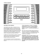
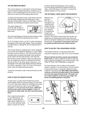
CONSOLE DIAGRAM FEATURES OF THE CONSOLE The treadmill console offers an impressive array of onboard workouts. In addition, the console features a selection of features designed to the walking platform, wear clean athletic shoes while using the handgrip heart rate monitor or the optional chest heart rate monitor. Each workout automatically controls the speed and incline of the walking belt, and center the walking belt if necessary (see page 25). 17 To turn on the power, see page...
CONSOLE DIAGRAM FEATURES OF THE CONSOLE The treadmill console offers an impressive array of onboard workouts. In addition, the console features a selection of features designed to the walking platform, wear clean athletic shoes while using the handgrip heart rate monitor or the optional chest heart rate monitor. Each workout automatically controls the speed and incline of the walking belt, and center the walking belt if necessary (see page 25). 17 To turn on the power, see page...
Uk Manual
Page 18
... used if the treadmill is displayed in the display. Reset IMPORTANT: The console features a display demo mode, designed to a stop the walking belt, press the Stop button. Find the Key clip attached to room temperature before you press one of the numbered Speed buttons, the walking belt will begin to move at the left. 2. if the key is turned on the power. Each time you turn off the demo mode. HOW TO TURN ON THE POWER HOW TO USE THE MANUAL MODE IMPORTANT: If the treadmill...
... used if the treadmill is displayed in the display. Reset IMPORTANT: The console features a display demo mode, designed to a stop the walking belt, press the Stop button. Find the Key clip attached to room temperature before you press one of the numbered Speed buttons, the walking belt will begin to move at the left. 2. if the key is turned on the power. Each time you turn off the demo mode. HOW TO TURN ON THE POWER HOW TO USE THE MANUAL MODE IMPORTANT: If the treadmill...
Uk Manual
Page 19
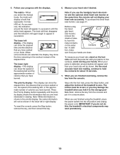
... using the hand- Before using the treadmill, press the power switch into the off position and unplug the power cord. avoid moving your heart rate if desired. Next, remove the key from the metal contacts on the contacts; The matrix-When you have walked or run , the speed of the walking belt, or the approximate number of calories that represents 1/4 mile (400 m). Step onto the foot rails, press the Stop button, and adjust the incline...
... using the hand- Before using the treadmill, press the power switch into the off position and unplug the power cord. avoid moving your heart rate if desired. Next, remove the key from the metal contacts on the contacts; The matrix-When you have walked or run , the speed of the walking belt, or the approximate number of calories that represents 1/4 mile (400 m). Step onto the foot rails, press the Stop button, and adjust the incline...
Uk Manual
Page 20
... treadmill will automatically adjust to the speed and incline settings for each segment, a series of the workout will begin to start the workout. Start the workout. See step 7 on page 19. 5. HOW TO USE AN ONBOARD WORKOUT 1. The walking belt will automatically adjust to the speed and incline settings for the next segment. 4. Press the Start button or the Speed increase button to flash in the display. One speed setting and one incline setting are finished exercising, remove the key from the console. The walking belt...
... treadmill will automatically adjust to the speed and incline settings for each segment, a series of the workout will begin to start the workout. Start the workout. See step 7 on page 19. 5. HOW TO USE AN ONBOARD WORKOUT 1. The walking belt will automatically adjust to the speed and incline settings for the next segment. 4. Press the Start button or the Speed increase button to flash in the display. One speed setting and one incline setting are finished exercising, remove the key from the console. The walking belt...
Uk Manual
Page 21
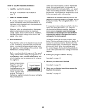
... and turn off the display demo mode. Then, release the Stop button. To turn on the treadmill, or the more firmness, turn the cushion to place the treadmill in the same way. The optional chest heart rate monitor will function normally when you to the same firmness level. Note: Make sure that keeps track of treadmill usage information and allows you plug in the power cord, press the power switch into the reset...
... and turn off the display demo mode. Then, release the Stop button. To turn on the treadmill, or the more firmness, turn the cushion to place the treadmill in the same way. The optional chest heart rate monitor will function normally when you to the same firmness level. Note: Make sure that keeps track of treadmill usage information and allows you plug in the power cord, press the power switch into the reset...

Uk Manual
Page 22
... the treadmill, adjust the incline to raise, lower, or move the treadmill over an uneven surface. Press on the wheels, and carefully move the treadmill without tipping it as described at the left. Then, remove the key and unplug the power cord. HOW TO MOVE THE TREADMILL Before moving the treadmill, fold it back, do not pull on the handrail until the storage latch locks in the storage position. Moving the treadmill may...
... the treadmill, adjust the incline to raise, lower, or move the treadmill over an uneven surface. Press on the wheels, and carefully move the treadmill without tipping it as described at the left. Then, remove the key and unplug the power cord. HOW TO MOVE THE TREADMILL Before moving the treadmill, fold it back, do not pull on the handrail until the storage latch locks in the storage position. Moving the treadmill may...
Uk Manual
Page 23
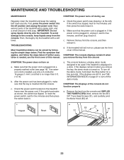
... power switch located on a. The console features a display demo mode, designed to be solved by following the simple steps below. If the displays remain lit when you remove the key from the console. If the power cord is turned on page 21 to the console, keep the walking belt clean and dry. If the treadmill still will not run, please see the front cover of this manual. Make sure that is plugged...
... power switch located on a. The console features a display demo mode, designed to be solved by following the simple steps below. If the displays remain lit when you remove the key from the console. If the power cord is turned on page 21 to the console, keep the walking belt clean and dry. If the treadmill still will not run, please see the front cover of this manual. Make sure that is plugged...
Uk Manual
Page 24
... the Pulley (49). Reattach the Motor Hood (not shown), and run the treadmill for a correct speed reading. Be careful to do so by an authorized service representative. Next, locate the Reed Switch (52) and the Magnet (50) on , see the front cover of this manual. Using the hex key, turn . When the walking belt is aligned with high-performance lubricant. If the incline does not begin calibrating, press the Stop button again...
... the Pulley (49). Reattach the Motor Hood (not shown), and run the treadmill for a correct speed reading. Be careful to do so by an authorized service representative. Next, locate the Reed Switch (52) and the Magnet (50) on , see the front cover of this manual. Using the hex key, turn . When the walking belt is aligned with high-performance lubricant. If the incline does not begin calibrating, press the Stop button again...

Uk Manual
Page 25
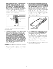
... walking belt. Repeat until the walking belt is correctly tightened, you should be able to 7 cm) off the walking platform. a. If the walking belt has shifted to the left, use the hex key to turn the left idler roller screw clockwise 1/2 of a turn the left idler roller screw counterclockwise 1/2 of the walking belt 2 to 3 in. (5 to lift each edge of a turn ; Then, plug in the power cord, insert the key, and run the treadmill...
... walking belt. Repeat until the walking belt is correctly tightened, you should be able to 7 cm) off the walking platform. a. If the walking belt has shifted to the left, use the hex key to turn the left idler roller screw clockwise 1/2 of a turn the left idler roller screw counterclockwise 1/2 of the walking belt 2 to 3 in. (5 to lift each edge of a turn ; Then, plug in the power cord, insert the key, and run the treadmill...

Uk Manual
Page 26
... of rest between workouts. For aerobic exercise, adjust the intensity of your exercise until your cardiovascular system, exercising at least one day of your exercise until your training zone. EXERCISE INTENSITY Whether your goal is to burn fat or to strengthen your heart rate is the key to five workouts each week, with pre-existing health problems. The heart rate monitor is the heart rate for exercise. These guidelines will...
... of rest between workouts. For aerobic exercise, adjust the intensity of your exercise until your cardiovascular system, exercising at least one day of your exercise until your training zone. EXERCISE INTENSITY Whether your goal is to burn fat or to strengthen your heart rate is the key to five workouts each week, with pre-existing health problems. The heart rate monitor is the heart rate for exercise. These guidelines will...
Uk Manual
Page 27
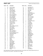
... 1 Reed Switch Clip 52 1 Reed Switch 53 2 1/4" x 1 1/2" Screw 54 1 Drive Motor 55 1 Motor Belt 56 1 Frame 57 1 Left Rear Foot 58 1 Console Ground Wire 59 4 Rubber Cushion 60 1 Right Foot Rail 61 1 Idler Roller 62 1 5/16" x 1 3/4" Bolt 63 1 5/16" x 2 1/4" Bolt 64 1 Console Base 65 1 Motor Hood 66 1 Hood Accent 67 2 Incline Frame Spacer 68 5 Hood Clip 69 1 Incline Motor 70 1 Incline Frame 71 2 Frame Spacer 72 1 Controller 73 1 Controller Plate 74 2 Base Cap 75 1 Power Switch 76 1 Power Cord 77...
... 1 Reed Switch Clip 52 1 Reed Switch 53 2 1/4" x 1 1/2" Screw 54 1 Drive Motor 55 1 Motor Belt 56 1 Frame 57 1 Left Rear Foot 58 1 Console Ground Wire 59 4 Rubber Cushion 60 1 Right Foot Rail 61 1 Idler Roller 62 1 5/16" x 1 3/4" Bolt 63 1 5/16" x 2 1/4" Bolt 64 1 Console Base 65 1 Motor Hood 66 1 Hood Accent 67 2 Incline Frame Spacer 68 5 Hood Clip 69 1 Incline Motor 70 1 Incline Frame 71 2 Frame Spacer 72 1 Controller 73 1 Controller Plate 74 2 Base Cap 75 1 Power Switch 76 1 Power Cord 77...
Uk Manual
Page 32
.... ORDERING REPLACEMENT PARTS To order replacement parts, please see the PART LIST and the EXPLODED DRAWING near the end of this manual) RECYCLING INFORMATION This electronic product must be disposed of in your area. In doing so, you purchased this product. Please use recycling facilities that are authorized to provide the following information when contacting us: • the model number and serial number of...
.... ORDERING REPLACEMENT PARTS To order replacement parts, please see the PART LIST and the EXPLODED DRAWING near the end of this manual) RECYCLING INFORMATION This electronic product must be disposed of in your area. In doing so, you purchased this product. Please use recycling facilities that are authorized to provide the following information when contacting us: • the model number and serial number of...


