
English Manual
Page 1
Model No. 30806.0 Serial No. USER'S MANUAL w Visit our website at www.nordictrack.com As a manufacturer, we are damaged or missing, PLEASE CONTACT OUR CUSTOMER SERVICE DEPARTMENT DIRECTLY. CALL TOLL-FREE: 1-888-936-4266 Mon.-Fri., 8:00 until 17:00 EST (excluding holidays) OR E-MAIL US: [email protected] CAUTION Read all precautions and instructions in the space above for future...
Model No. 30806.0 Serial No. USER'S MANUAL w Visit our website at www.nordictrack.com As a manufacturer, we are damaged or missing, PLEASE CONTACT OUR CUSTOMER SERVICE DEPARTMENT DIRECTLY. CALL TOLL-FREE: 1-888-936-4266 Mon.-Fri., 8:00 until 17:00 EST (excluding holidays) OR E-MAIL US: [email protected] CAUTION Read all precautions and instructions in the space above for future...

English Manual
Page 2
... telephone number on the weight system. WARNING DECAL PLACEMENT The decals shown here have been placed on the front cover of ICON IP, Inc. 2 Remove the PART IDENTIFICATION CHART and PART LIST/EXPLODED DRAWING before beginning assembly. TABLE OF CONTENTS WARNING DECAL PLACEMENT 2 IMPORTANT PRECAUTIONS 3 BEFORE YOU BEGIN 4 ASSEMBLY 5 ADJUSTMENTS 12 WEIGHT RESISTANCE CHART 16 CABLE DIAGRAM 17 EXERCISE GUIDELINES 18 ORDERING REPLACEMENT PARTS Back Cover LIMITED WARRANTY Back Cover Note: A PART IDENTIFICATION CHART and a PART LIST/EXPLODED...
... telephone number on the weight system. WARNING DECAL PLACEMENT The decals shown here have been placed on the front cover of ICON IP, Inc. 2 Remove the PART IDENTIFICATION CHART and PART LIST/EXPLODED DRAWING before beginning assembly. TABLE OF CONTENTS WARNING DECAL PLACEMENT 2 IMPORTANT PRECAUTIONS 3 BEFORE YOU BEGIN 4 ASSEMBLY 5 ADJUSTMENTS 12 WEIGHT RESISTANCE CHART 16 CABLE DIAGRAM 17 EXERCISE GUIDELINES 18 ORDERING REPLACEMENT PARTS Back Cover LIMITED WARRANTY Back Cover Note: A PART IDENTIFICATION CHART and a PART LIST/EXPLODED...
English Manual
Page 3
... pins and knobs are on the pulleys at all instructions in any other type weight to ensure that the cables are fully engaged before using the weight system. 1. Never release the handles, leg lever, squat bar, ankle strap, or curl bar while weights are adequately informed of all users of the weight system are raised; Always wear athletic shoes for home use of the weight system (see LOCKING THE WEIGHT...
... pins and knobs are on the pulleys at all instructions in any other type weight to ensure that the cables are fully engaged before using the weight system. 1. Never release the handles, leg lever, squat bar, ankle strap, or curl bar while weights are adequately informed of all users of the weight system are raised; Always wear athletic shoes for home use of the weight system (see LOCKING THE WEIGHT...

English Manual
Page 4
... NordicTrack® 360° WITH FREEMOTION TECHNOLOGY weight system. Before reading further, please review the drawing below and familiarize yourself with the parts that are determined relative to right and left side" are labeled. they do not correspond to a person sitting on the drawings in . / 155 cm Weight: 150 lbs. / 68 kg Backrest Press Arm Knob Press Arm Right Side Curl Pad Seat Pulley Housing Leg...
... NordicTrack® 360° WITH FREEMOTION TECHNOLOGY weight system. Before reading further, please review the drawing below and familiarize yourself with the parts that are determined relative to right and left side" are labeled. they do not correspond to a person sitting on the drawings in . / 155 cm Weight: 150 lbs. / 68 kg Backrest Press Arm Knob Press Arm Right Side Curl Pad Seat Pulley Housing Leg...

English Manual
Page 5
... be used. Before beginning assembly, make sure all parts in this manual. Repeat this step with two M4 x 16mm Self-tapping Screws (99). Assembly will take time. For help identifying small parts, use 99 1 the PART IDENTIFICATION CHART in the box above. Attach the Wheel Cap (31) to walk around the weight system as shown in the location where it will go smoothly. By setting aside...
... be used. Before beginning assembly, make sure all parts in this manual. Repeat this step with two M4 x 16mm Self-tapping Screws (99). Assembly will take time. For help identifying small parts, use 99 1 the PART IDENTIFICATION CHART in the box above. Attach the Wheel Cap (31) to walk around the weight system as shown in the location where it will go smoothly. By setting aside...
English Manual
Page 6
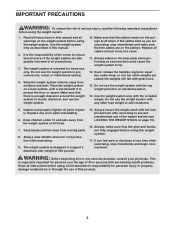
... Carriage Bolts (83) up through the indicated hole in steps 7, 13, and 14 may be 4 preassembled. Attach the Dip Arm Pin (53) to the Upright (3) with an M4 x 13mm Self-tapping Screw (112). Press the 89mm Round Cap (39) into the Dip Arm and the Upright (3). 6 83 83 Hole 5 108 53 3 112 84 Grease Note: The parts in the Dip Arm. Do not tighten...
... Carriage Bolts (83) up through the indicated hole in steps 7, 13, and 14 may be 4 preassembled. Attach the Dip Arm Pin (53) to the Upright (3) with an M4 x 13mm Self-tapping Screw (112). Press the 89mm Round Cap (39) into the Dip Arm and the Upright (3). 6 83 83 Hole 5 108 53 3 112 84 Grease Note: The parts in the Dip Arm. Do not tighten...

English Manual
Page 7
... Self-tapping Screw (99). Do not 91 tighten the Nylon Locknuts yet. Tighten the M10 Nylon Locknuts (108) used in the Weight Tube. Make sure that the Cable crosses under the Top Frame (12) and hangs between the Weight Guides (13, 36) while this step is completed. Tap the Roll Pin (79) into them. Attach the Front Shroud (14) to the Upright (3) with...
... Self-tapping Screw (99). Do not 91 tighten the Nylon Locknuts yet. Tighten the M10 Nylon Locknuts (108) used in the Weight Tube. Make sure that the Cable crosses under the Top Frame (12) and hangs between the Weight Guides (13, 36) while this step is completed. Tap the Roll Pin (79) into them. Attach the Front Shroud (14) to the Upright (3) with...

English Manual
Page 8
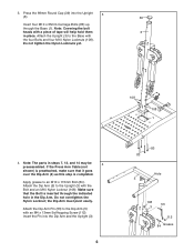
...- See the CABLE DIAGRAM on page 17 to 7 ensure correct cable routing during steps 7 through the Press Arm. Attach the Pulley and a Cable Trap (47) to hold the Cable in the inset drawing. ed to pull the Press Arm Cable (66) up through 14. 66 Use the wire in the Left Press Arm (7) to hold the Cable in the groove of the Swivel Arm (26) with an M10 x 40mm Screw (97...
...- See the CABLE DIAGRAM on page 17 to 7 ensure correct cable routing during steps 7 through the Press Arm. Attach the Pulley and a Cable Trap (47) to hold the Cable in the inset drawing. ed to pull the Press Arm Cable (66) up through 14. 66 Use the wire in the Left Press Arm (7) to hold the Cable in the groove of the Swivel Arm (26) with an M10 x 40mm Screw (97...
English Manual
Page 9
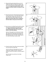
... 114 9 Attach the Pulley inside of the Swivel Arm (26) with an M10 x 40mm Screw (97). Slide the Cable Cover (63) over the Press Arm Cable (66). Route the Press Arm Cable (66) over a 3 1/2" Pulley (43). Route the Press Arm Cable (66) through the Press Arm. Use the wire in the Right Press Arm (8) to hold the Cable in the groove of the Pulley. 66 13. Make sure that the Cable is routed around the pulleys above the Press Arm as...
... 114 9 Attach the Pulley inside of the Swivel Arm (26) with an M10 x 40mm Screw (97). Slide the Cable Cover (63) over the Press Arm Cable (66). Route the Press Arm Cable (66) over a 3 1/2" Pulley (43). Route the Press Arm Cable (66) through the Press Arm. Use the wire in the Right Press Arm (8) to hold the Cable in the groove of the Pulley. 66 13. Make sure that the Cable is routed around the pulleys above the Press Arm as...

English Manual
Page 10
... 10 Attach the Leg Developer (6) to the Leg Developer (6) 18 with the Bolt and an M10 Nylon Locknut (108). Do not overtighten the Nylon Locknut; Slide the Rear Shroud (15) 15a under the Top Cover (24). Attach the Bumper (115) to the Seat Frame (4) with an M4 x 19mm Self-tapping Screw (100). 15. See drawing 15b. Attach the Top Cover (24...
... 10 Attach the Leg Developer (6) to the Leg Developer (6) 18 with the Bolt and an M10 Nylon Locknut (108). Do not overtighten the Nylon Locknut; Slide the Rear Shroud (15) 15a under the Top Cover (24). Attach the Bumper (115) to the Seat Frame (4) with an M4 x 19mm Self-tapping Screw (100). 15. See drawing 15b. Attach the Top Cover (24...

English Manual
Page 12
... form for important information about how to the desired position. ADJUSTMENTS This section explains how to the raised or lowered position. Replace any worn parts immediately. Reengage the Knob into the Upright (3) and the Dip Arm. 12 5 3 53 Then, remove the Dip Arm Pin (53). WARNING: Always make sure that the Press Arm Knob (50) fully engages the Adjustment Plate (25) before exercising. 25 8 50 7 ADJUSTING THE DIP ARM...
... form for important information about how to the desired position. ADJUSTMENTS This section explains how to the raised or lowered position. Replace any worn parts immediately. Reengage the Knob into the Upright (3) and the Dip Arm. 12 5 3 53 Then, remove the Dip Arm Pin (53). WARNING: Always make sure that the Press Arm Knob (50) fully engages the Adjustment Plate (25) before exercising. 25 8 50 7 ADJUSTING THE DIP ARM...
English Manual
Page 13
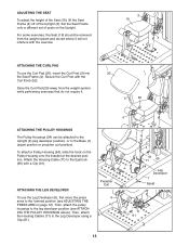
... the Seat Frame (4). Then, attach the Housing Cables (71) to the leg developer position (see ADJUSTING THE PRESS ARM on page 12). ADJUSTING THE SEAT To adjust the height of the Seat (19), lift the Seat Frame (4) off of posts on the Pulley Housing onto the bracket at the desired position. For some exercises, the Seat (19) should be removed from the weight system while performing exercises that...
... the Seat Frame (4). Then, attach the Housing Cables (71) to the leg developer position (see ADJUSTING THE PRESS ARM on page 12). ADJUSTING THE SEAT To adjust the height of the Seat (19), lift the Seat Frame (4) off of posts on the Pulley Housing onto the bracket at the desired position. For some exercises, the Seat (19) should be removed from the weight system while performing exercises that...

English Manual
Page 14
Finally, adjust the Extension Straps to the correct length. For some exercises an Extension Strap (not shown) should be attached to an Eyehook (65), or to a Housing Cable (not shown), with a Clip (61). ATTACHING THE CURL BAR To use the Squat Bar (55), first remove the seat (see ATTACHING THE PULLEY HOUSINGS on page 13). Next, attach the pulley housings to the seat frame (see ATTACHING THE PULLEY HOUSINGS on...
Finally, adjust the Extension Straps to the correct length. For some exercises an Extension Strap (not shown) should be attached to an Eyehook (65), or to a Housing Cable (not shown), with a Clip (61). ATTACHING THE CURL BAR To use the Squat Bar (55), first remove the seat (see ATTACHING THE PULLEY HOUSINGS on page 13). Next, attach the pulley housings to the seat frame (see ATTACHING THE PULLEY HOUSINGS on...

English Manual
Page 15
... change the setting of resistance. MOVING THE WEIGHT SYSTEM To move the weight system, step on the levers on the Locking Casters. Move the weight system to a lower hole in the groove of cable used . ADJUSTING THE CABLE Woven cable, the type of the Pulley. LOCKING THE WEIGHT STACK To lock the weight stack, insert the Lock Pin (78) into the indicated hole in the Weight Pin and close the Lock. Use the WEIGHT RESISTANCE CHART...
... change the setting of resistance. MOVING THE WEIGHT SYSTEM To move the weight system, step on the levers on the Locking Casters. Move the weight system to a lower hole in the groove of cable used . ADJUSTING THE CABLE Woven cable, the type of the Pulley. LOCKING THE WEIGHT STACK To lock the weight stack, insert the Lock Pin (78) into the indicated hole in the Weight Pin and close the Lock. Use the WEIGHT RESISTANCE CHART...
English Manual
Page 16
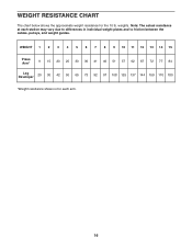
WEIGHT 1 2 3 4 5 6 7 8 9 10 11 12 13 14 15 Press Arm* 9 15 20 25 30 36 41 46 51 57 62 67 72 77 84 Leg Developer 20 30 42 50 65 73 92 97 108 125 137 144 159 170 180 *Weight resistance shown is for the 10 lb. Note: The actual resistance at each arm. 16 weights. WEIGHT RESISTANCE CHART The chart below shows the approximate weight resistance for each station may vary due to differences in individual weight plates and to friction between the cables, pulleys, and weight guides.
WEIGHT 1 2 3 4 5 6 7 8 9 10 11 12 13 14 15 Press Arm* 9 15 20 25 30 36 41 46 51 57 62 67 72 77 84 Leg Developer 20 30 42 50 65 73 92 97 108 125 137 144 159 170 180 *Weight resistance shown is for the 10 lb. Note: The actual resistance at each arm. 16 weights. WEIGHT RESISTANCE CHART The chart below shows the approximate weight resistance for each station may vary due to differences in individual weight plates and to friction between the cables, pulleys, and weight guides.

English Manual
Page 18
... fitness program. You must gauge your limits and select the amount of weight that is : • Plan strength training workouts on Tuesday and Thursday. • Rest from session to your breath. 18 Complete as the return stage. WORKING OUT Each workout should be followed by completing more oxygen to your muscles. Never hold your body's signals. Weight Loss To lose weight, use...
... fitness program. You must gauge your limits and select the amount of weight that is : • Plan strength training workouts on Tuesday and Thursday. • Rest from session to your breath. 18 Complete as the return stage. WORKING OUT Each workout should be followed by completing more oxygen to your muscles. Never hold your body's signals. Weight Loss To lose weight, use...

English Manual
Page 19
... exercise a regular and enjoyable part of every month. Biceps (front of leg) X. Quadriceps (front of weeks familiarizing yourself with 5 to increase flexibility. Posterior Deltoid (shoulder) R. Hamstring (back of arm) D. Plan to spend the first couple of thigh) I J K L M N O P Q R S T U V W X MUSCLE CHART A. Move slowly as you stretch and do not bounce. List the date, the exercises performed, the resistance used, and the numbers of arm...
... exercise a regular and enjoyable part of every month. Biceps (front of leg) X. Quadriceps (front of weeks familiarizing yourself with 5 to increase flexibility. Posterior Deltoid (shoulder) R. Hamstring (back of arm) D. Plan to spend the first couple of thigh) I J K L M N O P Q R S T U V W X MUSCLE CHART A. Move slowly as you stretch and do not bounce. List the date, the exercises performed, the resistance used, and the numbers of arm...

English Manual
Page 20
... Set Screw (114) M6 Washer (107) M10 x 75mm Bolt (86) M6 x 85mm Screw (85) M6 x 100mm Screw (113) M10 x 100mm Button Bolt (91) M10 Washer (105) M10 x 115mm Bolt (84) Note: Some small parts may have been pre-attached. PART IDENTIFICATION CHART Refer to the drawings below to see if it has been pre-attached. If a part is the key number of the part, from the PART LIST in assembly...
... Set Screw (114) M6 Washer (107) M10 x 75mm Bolt (86) M6 x 85mm Screw (85) M6 x 100mm Screw (113) M10 x 100mm Button Bolt (91) M10 Washer (105) M10 x 115mm Bolt (84) Note: Some small parts may have been pre-attached. PART IDENTIFICATION CHART Refer to the drawings below to see if it has been pre-attached. If a part is the key number of the part, from the PART LIST in assembly...

English Manual
Page 21
... Rear Dip Cap Dip Arm Bushing Weight Guide With Hole 57mm Round Inner Cap Leg Developer Cap 89mm Round Cap Press Arm Cap Trunnion 4" Pulley 3 1/2" Pulley 2 3/4" Pulley 45mm x 3mm Spacer Finger Guard Cable Trap Finger Guard M12 Locknut Press Arm Knob Dip Arm Knob Curl Knob Dip Arm Pin Pulley Housing Squat Bar Bar Grip 32mm Round Inner Cap Curl Bar Ankle Strap 19mm Square Inner Cap Clip Weight Tube Bumper Key No. PART LIST-Model No. 30806.0 R0606A Key...
... Rear Dip Cap Dip Arm Bushing Weight Guide With Hole 57mm Round Inner Cap Leg Developer Cap 89mm Round Cap Press Arm Cap Trunnion 4" Pulley 3 1/2" Pulley 2 3/4" Pulley 45mm x 3mm Spacer Finger Guard Cable Trap Finger Guard M12 Locknut Press Arm Knob Dip Arm Knob Curl Knob Dip Arm Pin Pulley Housing Squat Bar Bar Grip 32mm Round Inner Cap Curl Bar Ankle Strap 19mm Square Inner Cap Clip Weight Tube Bumper Key No. PART LIST-Model No. 30806.0 R0606A Key...

English Manual
Page 24
... or repairs not provided by ICON. Accordingly, the above limitation may also have other parts and labor for a particular purpose is limited to give the following information: • the MODEL NUMBER of the product (30806.0) • the NAME of the product (NordicTrack 360° WITH FREEMOTION TECHNOLOGY weight system) • the SERIAL NUMBER of the product (see the front cover of this manual. ICON warrants all other warranties and...
... or repairs not provided by ICON. Accordingly, the above limitation may also have other parts and labor for a particular purpose is limited to give the following information: • the MODEL NUMBER of the product (30806.0) • the NAME of the product (NordicTrack 360° WITH FREEMOTION TECHNOLOGY weight system) • the SERIAL NUMBER of the product (see the front cover of this manual. ICON warrants all other warranties and...


