
User Manual
Page 4
... airline personnel This device emits radio frequency radiation that could result in fire or electric shock. Follow the instructions of the antenna in blindness or other injury. Keep out of reach of hospital or airline staff. Keep these safety instructions where all those who use this Nikon product to prevent possible injury. Turn camera off immediately in the...
... airline personnel This device emits radio frequency radiation that could result in fire or electric shock. Follow the instructions of the antenna in blindness or other injury. Keep out of reach of hospital or airline staff. Keep these safety instructions where all those who use this Nikon product to prevent possible injury. Turn camera off immediately in the...
User Manual
Page 5
... may cause undesired operation. ii Notices • No part of the manuals included with this product may be held liable for Customers in the U.S.A. Notice for any interference received, including interference that contain a radio transmitter are designed to which can radiate radio frequency energy and, if not installed and used in accordance with the limits for help. WT-1A FCC Radio Frequency Interference Statement This...
... may cause undesired operation. ii Notices • No part of the manuals included with this product may be held liable for Customers in the U.S.A. Notice for any interference received, including interference that contain a radio transmitter are designed to which can radiate radio frequency energy and, if not installed and used in accordance with the limits for help. WT-1A FCC Radio Frequency Interference Statement This...
User Manual
Page 8
... and warnings on digital imaging and photography. This icon indicates that may be sure to read before use to prevent damage to ongoing product support and education, continually-updated information is for use only in the number of ftp servers and wireless local area networks (LAN). Introduction Thank you for purchasing a WT-1 or WT-1A wireless transmitter for contact information: http://www.nikon-image.com/eng...
... and warnings on digital imaging and photography. This icon indicates that may be sure to read before use to prevent damage to ongoing product support and education, continually-updated information is for use only in the number of ftp servers and wireless local area networks (LAN). Introduction Thank you for purchasing a WT-1 or WT-1A wireless transmitter for contact information: http://www.nikon-image.com/eng...

User Manual
Page 9
... the Internet is a wireless LAN adapter that allows photographs to an ftp server. The WT-1 supports an infrastructure mode for direct wireless connection to be selected for upload. Wireless Networks The WT-1 wireless transmitter is not supported). The WT-1 supports the following systems: Windows XP Professional and Windows 2000 Professional. 2 CLC S OAU/VT DC IN ቤ LOCK POWER LINK BUSY WT-1 FTP server (with wireless LAN adapter) ቢ Configured using Wireless ( 15-17) and...
... the Internet is a wireless LAN adapter that allows photographs to an ftp server. The WT-1 supports an infrastructure mode for direct wireless connection to be selected for upload. Wireless Networks The WT-1 wireless transmitter is not supported). The WT-1 supports the following systems: Windows XP Professional and Windows 2000 Professional. 2 CLC S OAU/VT DC IN ቤ LOCK POWER LINK BUSY WT-1 FTP server (with wireless LAN adapter) ቢ Configured using Wireless ( 15-17) and...

User Manual
Page 11
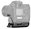
... the WT-1. 5 Place the camera on the WT-1 and rotate the knob in the camera setup menu to the USB connector. 7 Pass the cable over the guide on . 2 Before connecting the WT-1, set the USB option in the direction shown to fasten the WT-1 to the camera tripod mount. 6 Open the camera USB connector cover and connect the USB cable to PTP. 3 Turn the camera off. Attaching the WT-1 1 Turn the camera on the BL-2 batterychamber cover. 4 LOCK POWER LINK BUSY POWER LOCK POWER LOCK SET UP USB...
... the WT-1. 5 Place the camera on the WT-1 and rotate the knob in the camera setup menu to the USB connector. 7 Pass the cable over the guide on . 2 Before connecting the WT-1, set the USB option in the direction shown to fasten the WT-1 to the camera tripod mount. 6 Open the camera USB connector cover and connect the USB cable to PTP. 3 Turn the camera off. Attaching the WT-1 1 Turn the camera on the BL-2 batterychamber cover. 4 LOCK POWER LINK BUSY POWER LOCK POWER LOCK SET UP USB...

User Manual
Page 13
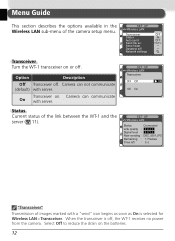
... memo button Audio output USB M Dust Off ref photo Battery Info Wireless LAN Firmware Version 4 Select On for "Status" ( 11). SET UP Wireless LAN Status Link quality Signal level Now sending Remaining Time left Connected 0 Frames 0 s 6 SET UP Wireless LAN Transceiver OFF Off ON On OK 5 Select Status from the Wireless LAN menu and confirm that "Connected" is shown for the Wireless LAN > Transceiver option in the camera setup menu...
... memo button Audio output USB M Dust Off ref photo Battery Info Wireless LAN Firmware Version 4 Select On for "Status" ( 11). SET UP Wireless LAN Status Link quality Signal level Now sending Remaining Time left Connected 0 Frames 0 s 6 SET UP Wireless LAN Transceiver OFF Off ON On OK 5 Select Status from the Wireless LAN menu and confirm that "Connected" is shown for the Wireless LAN > Transceiver option in the camera setup menu...

User Manual
Page 14
... 2 Press the button to send additional images (pictures will be SET UP Wireless LAN Auto send selected for...be replaced by the files uploaded from the camera during upload. Uploading Images 1 Select Off for Wireless LAN > Auto send (if Auto Send is on, new ...blue "sent" icon. 100-1 During Upload Do not remove the memory card from the camera. 7 During upload, images are marked with a green "sending" icon. Display the first picture to be sent in the thumbnail list. 3 Press the center of the multi selector while pressing the button. Repeat this process to view pictures...
... 2 Press the button to send additional images (pictures will be SET UP Wireless LAN Auto send selected for...be replaced by the files uploaded from the camera during upload. Uploading Images 1 Select Off for Wireless LAN > Auto send (if Auto Send is on, new ...blue "sent" icon. 100-1 During Upload Do not remove the memory card from the camera. 7 During upload, images are marked with a green "sending" icon. Display the first picture to be sent in the thumbnail list. 3 Press the center of the multi selector while pressing the button. Repeat this process to view pictures...

User Manual
Page 17
... the WT-1 is shown by the status LEDs and by the LINK LED, which blinks at different speeds to indicate link quality. The status of the link between the WT-1 and the server is receiving power from the camera. The Status LEDs The POWER LED lights when the WT-1 is shown by the Status display in the Wireless LAN menu. The BUSY LED lights while data are...
... the WT-1 is shown by the status LEDs and by the LINK LED, which blinks at different speeds to indicate link quality. The status of the link between the WT-1 and the server is receiving power from the camera. The Status LEDs The POWER LED lights when the WT-1 is shown by the Status display in the Wireless LAN menu. The BUSY LED lights while data are...
User Manual
Page 19
... is selected for Wireless LAN > Transceiver. Network settings OFF OFF RAW+J Transceiver Turn the WT-1 transceiver on the batteries. 12 Camera can not communicate (default) with server. SET UP Wireless LAN Transceiver Status Auto send Send file as On is off . SET UP Wireless LAN Transceiver OFF Off OK ON On SET UP Wireless LAN Status Link quality Signal level Now sending Remaining Time left Connected DSC_0001.JPG 1 Frames...
... is selected for Wireless LAN > Transceiver. Network settings OFF OFF RAW+J Transceiver Turn the WT-1 transceiver on the batteries. 12 Camera can not communicate (default) with server. SET UP Wireless LAN Transceiver Status Auto send Send file as On is off . SET UP Wireless LAN Transceiver OFF Off OK ON On SET UP Wireless LAN Status Link quality Signal level Now sending Remaining Time left Connected DSC_0001.JPG 1 Frames...
User Manual
Page 21
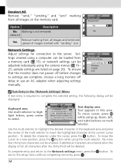
... dialog will be displayed. Option Description No Marking is not removed. (default) No OK Yes Remove marking from a memory card ( 15), or network settings can be adjusted individually using a computer can be entered; Settings created using the camera menus ( 15- 25; To ensure that the monitor does not power off delay or use an AC adapter when adjusting settings manually. SET UP Wireless LAN Network settings Load settings file? To move...
... dialog will be displayed. Option Description No Marking is not removed. (default) No OK Yes Remove marking from a memory card ( 15), or network settings can be adjusted individually using a computer can be entered; Settings created using the camera menus ( 15- 25; To ensure that the monitor does not power off delay or use an AC adapter when adjusting settings manually. SET UP Wireless LAN Network settings Load settings file? To move...
User Manual
Page 22
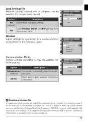
... wireless network is set up. Option Description No Exit without changing settings. (default) Load Wireless, TCP/IP, and FTP settings from the web sites listed on page 1 of the camera memory card using a CompactFlash card reader or PCMCIA memory card adapter. Ad-hoc Direct peer-to-peer wireless connection to wireless network is via ac(default) cess point. SET UP Wireless LAN Load settings file? No OK Yes SET UP Wireless LAN Wireless Communication mode SSID Encryption Channel SET UP Wireless...
... wireless network is set up. Option Description No Exit without changing settings. (default) Load Wireless, TCP/IP, and FTP settings from the web sites listed on page 1 of the camera memory card using a CompactFlash card reader or PCMCIA memory card adapter. Ad-hoc Direct peer-to-peer wireless connection to wireless network is via ac(default) cess point. SET UP Wireless LAN Load settings file? No OK Yes SET UP Wireless LAN Wireless Communication mode SSID Encryption Channel SET UP Wireless...
User Manual
Page 24
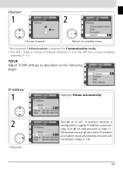
... automatically. Channel* 1 SET UP Wireless LAN Channel 01 OK Choose channel.† 2 SET UP Wireless LAN Wireless Communication mode SSID Encryption Channel Return to wireless menu. * Not required if Infrastructure is configured to supply IP address automatically, turn ✔ on and proceed to Step 11. If wireless network is selected for Communication mode. † The WT-1 offers a choice of thirteen channels (1-13), the WT-1A a choice of eleven channels (1-11...
... automatically. Channel* 1 SET UP Wireless LAN Channel 01 OK Choose channel.† 2 SET UP Wireless LAN Wireless Communication mode SSID Encryption Channel Return to wireless menu. * Not required if Infrastructure is configured to supply IP address automatically, turn ✔ on and proceed to Step 11. If wireless network is selected for Communication mode. † The WT-1 offers a choice of thirteen channels (1-13), the WT-1A a choice of eleven channels (1-11...

User Manual
Page 30
..., press button to return to user User menu. Password 7 Press multi selector to left to return to user menu. 4 SET UP Wireless LAN 5 User User ID anonymous Password SET UP ʴ cursor Input OK 0123456789 : ; ?@A B C D E F GH I J K L MNOPQR S T U VWX Y Z [ ] _abcde f gh i j k lm nopq r s t uvwx y z { } Display text entry dialog ( 14). Password will be disguised as row User ID anonymous of dots when displayed in ftp menu. SET UP Wireless LAN User User ID anonymous Password 2 SET UP...
..., press button to return to user User menu. Password 7 Press multi selector to left to return to user menu. 4 SET UP Wireless LAN 5 User User ID anonymous Password SET UP ʴ cursor Input OK 0123456789 : ; ?@A B C D E F GH I J K L MNOPQR S T U VWX Y Z [ ] _abcde f gh i j k lm nopq r s t uvwx y z { } Display text entry dialog ( 14). Password will be disguised as row User ID anonymous of dots when displayed in ftp menu. SET UP Wireless LAN User User ID anonymous Password 2 SET UP...
User Manual
Page 33
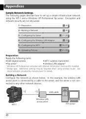
... DC IN LOCK POWER LINK BUSY WT-1 LAN cable Wireless LAN access point FTP server 26 Building a Network Configure the network as shown below. Additional settings may be required when using the WT-1 and a Windows XP Professional ftp server. Appendices Sample Network Settings The following items: • D2H digital camera • WT-1 wireless transmitter • ftp server1 • wireless LAN adapter2 1 Windows XP Professional computer with Internet Information Services (IIS) installed. 2 Bridge...
... DC IN LOCK POWER LINK BUSY WT-1 LAN cable Wireless LAN access point FTP server 26 Building a Network Configure the network as shown below. Additional settings may be required when using the WT-1 and a Windows XP Professional ftp server. Appendices Sample Network Settings The following items: • D2H digital camera • WT-1 wireless transmitter • ftp server1 • wireless LAN adapter2 1 Windows XP Professional computer with Internet Information Services (IIS) installed. 2 Bridge...
User Manual
Page 34
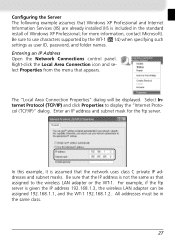
... Windows XP Professional and Internet Information Services (IIS) are already installed (IIS is given the IP address 192.168.1.3, the wireless LAN adapter can be assigned 192.168.1.1, and the WT-1 192.168.1.2. Entering an IP Address Open the Network Connections control panel. All addresses must be displayed. Right-click the Local Area Connection icon and select Properties from the menu that the network uses...
... Windows XP Professional and Internet Information Services (IIS) are already installed (IIS is given the IP address 192.168.1.3, the wireless LAN adapter can be assigned 192.168.1.1, and the WT-1 192.168.1.2. Entering an IP Address Open the Network Connections control panel. All addresses must be displayed. Right-click the Local Area Connection icon and select Properties from the menu that the network uses...

User Manual
Page 38
... adapter should be within a few meters with no obstacles between them. 1 Select On for the Wireless LAN > Transceiver option in the camera setup menu. To check the connection from the camera, select Status from the Wireless LAN menu and confirm that a connection has been established. For information on ftp server ( 28). SET UP Wireless LAN Status Link quality Signal level Now sending Remaining Time left Connected...
... adapter should be within a few meters with no obstacles between them. 1 Select On for the Wireless LAN > Transceiver option in the camera setup menu. To check the connection from the camera, select Status from the Wireless LAN menu and confirm that a connection has been established. For information on ftp server ( 28). SET UP Wireless LAN Status Link quality Signal level Now sending Remaining Time left Connected...
User Manual
Page 41
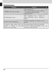
WT-1 hardware error. Contact a Nikon-authorized service represen- - tenna. - Turn transceiver off and check settings nected" or "Failure," or ftp server for WT-1, wireless LAN adapter or ac- 26 does not list connection. tative. Change orientation of camera or an- Excessive radio interference. Troubleshooting Problem Solution "POWER" LED does not light. • Turn camera on. 4 • Press shutter-release button halfway - to activate exposure meters. • Reattach WT-1. 4 All LEDs blink at once. Connection status shows...
WT-1 hardware error. Contact a Nikon-authorized service represen- - tenna. - Turn transceiver off and check settings nected" or "Failure," or ftp server for WT-1, wireless LAN adapter or ac- 26 does not list connection. tative. Change orientation of camera or an- Excessive radio interference. Troubleshooting Problem Solution "POWER" LED does not light. • Turn camera on. 4 • Press shutter-release button halfway - to activate exposure meters. • Reattach WT-1. 4 All LEDs blink at once. Connection status shows...
User Manual
Page 42
.... 35 When installed as connections that contains a database of Windows Me, Windows 98, or Windows 95 computers. If a DHCP server is case sensitive. Can be assigned automatically. Notable for wireless "hot spots" but is divided into 14 channels, each network can communicate with the router or operating system. A DHCP server will be used for its database. ESS-ID (Extended Service Set ID...
.... 35 When installed as connections that contains a database of Windows Me, Windows 98, or Windows 95 computers. If a DHCP server is case sensitive. Can be assigned automatically. Notable for wireless "hot spots" but is divided into 14 channels, each network can communicate with the router or operating system. A DHCP server will be used for its database. ESS-ID (Extended Service Set ID...

User Manual
Page 43
... A." Private IP address An IP address that stands between a company network and the Internet. Proxy A server that is used depends on a network, required when sending and receiving packets. MAC (Media Access Control) Address A unique hardware address for connection to another . The WT-1 supports an infrastructure mode for each node in a TCP/IP network must have a unique IP address. One element of 10...
... A." Private IP address An IP address that stands between a company network and the Internet. Proxy A server that is used depends on a network, required when sending and receiving packets. MAC (Media Access Control) Address A unique hardware address for connection to another . The WT-1 supports an infrastructure mode for each node in a TCP/IP network must have a unique IP address. One element of 10...

User Manual
Page 46
... settings file?, 15 M MAC address, 21 ,29, 37 Mounting screw, 3 N Network settings, 14 Network settings files, 14 P Password, 23 POWER, 3, 34 Power contact, 3 S Send folder, 13 "Send" marking, 14 Send file as, 13 "Sending" marking, 14 "Sent" marking, 14 Settings files. See Wireless access point Antenna, 3 Auto send, 13 B BSS-ID, 16, 35 BUSY, 3, 10 C Channel, 17, 35 selection, 17 Connecting the WT...
... settings file?, 15 M MAC address, 21 ,29, 37 Mounting screw, 3 N Network settings, 14 Network settings files, 14 P Password, 23 POWER, 3, 34 Power contact, 3 S Send folder, 13 "Send" marking, 14 Send file as, 13 "Sending" marking, 14 "Sent" marking, 14 Settings files. See Wireless access point Antenna, 3 Auto send, 13 B BSS-ID, 16, 35 BUSY, 3, 10 C Channel, 17, 35 selection, 17 Connecting the WT...
