GS7xxTS-TPS Hardware Installation Guide
Page 3
Table of Contents Chapter 1 Introduction Overview 7 Features 7 Stacking 9 Package Contents 10 Chapter 2 Physical Description GS728TS Front-Panel and Back-Panel Configuration 12 GS728TPS Front-Panel and Back-Panel Configuration 13 GS752TS Front-Panel ... 3: Checking the Installation 26 Step 4: Connecting Devices to the Switch 26 Step 5: Installing an SFP Transceiver Module 27 Step 6: Installing Device as Stand-alone or Stack Master 28 Step 7: Applying AC Power 29 Step 8: Managing the Switch using a Web Browser or the PC Utility . . . . 30 Contents | 3
Table of Contents Chapter 1 Introduction Overview 7 Features 7 Stacking 9 Package Contents 10 Chapter 2 Physical Description GS728TS Front-Panel and Back-Panel Configuration 12 GS728TPS Front-Panel and Back-Panel Configuration 13 GS752TS Front-Panel ... 3: Checking the Installation 26 Step 4: Connecting Devices to the Switch 26 Step 5: Installing an SFP Transceiver Module 27 Step 6: Installing Device as Stand-alone or Stack Master 28 Step 7: Applying AC Power 29 Step 8: Managing the Switch using a Web Browser or the PC Utility . . . . 30 Contents | 3

GS7xxTS-TPS Hardware Installation Guide
Page 6
Your Smart Switch is intended for 1000M uplink or 2.5 Gbps stacking. The GS728TS, GS728TPS, GS752TS, and GS752TPS Smart Switch Hardware Installation Guide describes how to install and power on the front panel of which support nonstop ... a state-of-the-art, high-performance, IEEE-compliant network solution designed for users who require a large number of ports and want the power of your NETGEAR® ProSafeTM GS728TS, GS728TPS, GS752TS, or GS752TPS Smart Switch! Introduction | 6 The front panel also has six SFP ports, 2 of the switch which are combo ports...
Your Smart Switch is intended for 1000M uplink or 2.5 Gbps stacking. The GS728TS, GS728TPS, GS752TS, and GS752TPS Smart Switch Hardware Installation Guide describes how to install and power on the front panel of which support nonstop ... a state-of-the-art, high-performance, IEEE-compliant network solution designed for users who require a large number of ports and want the power of your NETGEAR® ProSafeTM GS728TS, GS728TPS, GS752TS, or GS752TPS Smart Switch! Introduction | 6 The front panel also has six SFP ports, 2 of the switch which are combo ports...

GS7xxTS-TPS Hardware Installation Guide
Page 7
... simple and intuitive manner. The switch also has six built-in a stack to a server or network backbone. Using these Gigabit slots, you can be used in half-duplex or full-duplex mode. The NETGEAR GS728TS, GS728TPS, GS752TS, or GS752TPS Smart Switch can be viewed and used... for 1000M uplink or 2.5 Gbps stacking. Features The following list identifies the key features of features for traffic prioritization. Chapter ...
... simple and intuitive manner. The switch also has six built-in a stack to a server or network backbone. Using these Gigabit slots, you can be used in half-duplex or full-duplex mode. The NETGEAR GS728TS, GS728TPS, GS752TS, or GS752TPS Smart Switch can be viewed and used... for 1000M uplink or 2.5 Gbps stacking. Features The following list identifies the key features of features for traffic prioritization. Chapter ...
GS7xxTS-TPS Hardware Installation Guide
Page 8
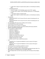
... ports. • GS752TS/GS752TPS: Port 51 and port 52 can be used as the stacking ports or as uplink ports. • Six 100/1000Mbps SFP slots and two 2.5Gbps ports for stacking. • Full NETGEAR Smart Switch functionality. • Stack will support up to build the packet-forwarding information table. GS728TS, GS728TPS, GS752TS, and...
... ports. • GS752TS/GS752TPS: Port 51 and port 52 can be used as the stacking ports or as uplink ports. • Six 100/1000Mbps SFP slots and two 2.5Gbps ports for stacking. • Full NETGEAR Smart Switch functionality. • Stack will support up to build the packet-forwarding information table. GS728TS, GS728TPS, GS752TS, and...

GS7xxTS-TPS Hardware Installation Guide
Page 9
...model LEDs: Power and Status LED, FAN status LED, Master LED, LED mode LED and Max PoE LED. • Stack ID LED to display stack member ID (1-6). • Store-and-Forward transmission to remove bad packets from the network. • Full-duplex IEEE ... • NETGEAR Green product series power-saving features: • Automatic power consumption adjustment based on the RJ-45 cable length. • Per port automatic power down . • IEEE802.3az, EEE (Energy Efficient Ethernet) compliance. Stacking A stack can become a stack master in the stack. The Stack Master provides a...
...model LEDs: Power and Status LED, FAN status LED, Master LED, LED mode LED and Max PoE LED. • Stack ID LED to display stack member ID (1-6). • Store-and-Forward transmission to remove bad packets from the network. • Full-duplex IEEE ... • NETGEAR Green product series power-saving features: • Automatic power consumption adjustment based on the RJ-45 cable length. • Per port automatic power down . • IEEE802.3az, EEE (Energy Efficient Ethernet) compliance. Stacking A stack can become a stack master in the stack. The Stack Master provides a...
GS7xxTS-TPS Hardware Installation Guide
Page 10
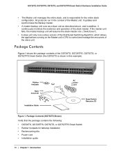
...kits • Power cord • Installation guide 10 | Chapter 1. If the master unit fails, the master-backup unit will assume the stack-master role. ("Switchover"). • A slave unit only runs a slave version of the Distributed Switching Algorithm, which allows the applications running ...that the package contains the following: • GS728TS, GS728TPS, GS752TS, or GS752TPS Smart Switch • Rubber footpads for the entire stack configuration. Rubber footpads Rack mount kit Installation Guide AC power cord Smart Switch Resource CD Figure 1. Package Contents Figure 1 shows the ...
...kits • Power cord • Installation guide 10 | Chapter 1. If the master unit fails, the master-backup unit will assume the stack-master role. ("Switchover"). • A slave unit only runs a slave version of the Distributed Switching Algorithm, which allows the applications running ...that the package contains the following: • GS728TS, GS728TPS, GS752TS, or GS752TPS Smart Switch • Rubber footpads for the entire stack configuration. Rubber footpads Rack mount kit Installation Guide AC power cord Smart Switch Resource CD Figure 1. Package Contents Figure 1 shows the ...
GS7xxTS-TPS Hardware Installation Guide
Page 12
Each port is capable of the NETGEAR GS728TS Smart Switch. Power, Fan, and Stack Master LEDs Stack ID LED Link/Speed/ACT LEDs Combo and Dedicated SFP Ports Factory Defaults Button Reset Button Figure 2. Physical Description | 12 2. Figure 2 illustrates the front ...automatically. GS728TS Front Panel 10/100/1000M Ethernet Ports Chapter 2. Up to two SFP ports (port 27 and 28) at a time can be used as stacking ports. Topics include: • GS728TS Front-Panel and Back-Panel Configuration • GS728TPS Front-Panel and Back-Panel Configuration • GS752TS Front-Panel and ...
Each port is capable of the NETGEAR GS728TS Smart Switch. Power, Fan, and Stack Master LEDs Stack ID LED Link/Speed/ACT LEDs Combo and Dedicated SFP Ports Factory Defaults Button Reset Button Figure 2. Physical Description | 12 2. Figure 2 illustrates the front ...automatically. GS728TS Front Panel 10/100/1000M Ethernet Ports Chapter 2. Up to two SFP ports (port 27 and 28) at a time can be used as stacking ports. Topics include: • GS728TS Front-Panel and Back-Panel Configuration • GS728TPS Front-Panel and Back-Panel Configuration • GS752TS Front-Panel and ...
GS7xxTS-TPS Hardware Installation Guide
Page 13
...can be used as stacking ports • Reset button to restart the device. • Recessed default reset button to restore the device back to two SFP ports (port 27 and 28) at a time can alternatively be used as stacking ports. Figure 3 illustrates the NETGEAR GS728TS Smart Switch ...back panel. Each port is capable of the NETGEAR GS728TPS Smart Switch. Power Connector GS728TPS Front-Panel and Back-Panel Configuration The GS728TPS Smart...
...can be used as stacking ports • Reset button to restart the device. • Recessed default reset button to restore the device back to two SFP ports (port 27 and 28) at a time can alternatively be used as stacking ports. Figure 3 illustrates the NETGEAR GS728TS Smart Switch ...back panel. Each port is capable of the NETGEAR GS728TPS Smart Switch. Power Connector GS728TPS Front-Panel and Back-Panel Configuration The GS728TPS Smart...
GS7xxTS-TPS Hardware Installation Guide
Page 14
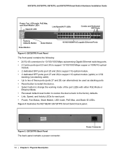
... a power connector. 14 | Chapter 2. Figure 5 illustrates the NETGEAR GS728TPS Smart Switch back panel. GS728TS, GS728TPS, GS752TS, and GS752TPS Smart Switch Hardware Installation Guide Power, Fan, LED mode, PoE Max, and Stack Master LEDs Stack ID LED Link/Speed/ACT LEDs Combo and Dedicated SFP Ports Factory... ports (port 27 and 28) to support 1G optical module (uplink) or 2.5G stacking (via stacking cable). • Up to two of these ports (ports 27 and 28) can alternatively be used as stacking ports • Reset button to restart the device. • Select button to change the...
... a power connector. 14 | Chapter 2. Figure 5 illustrates the NETGEAR GS728TPS Smart Switch back panel. GS728TS, GS728TPS, GS752TS, and GS752TPS Smart Switch Hardware Installation Guide Power, Fan, LED mode, PoE Max, and Stack Master LEDs Stack ID LED Link/Speed/ACT LEDs Combo and Dedicated SFP Ports Factory... ports (port 27 and 28) to support 1G optical module (uplink) or 2.5G stacking (via stacking cable). • Up to two of these ports (ports 27 and 28) can alternatively be used as stacking ports • Reset button to restart the device. • Select button to change the...
GS7xxTS-TPS Hardware Installation Guide
Page 15
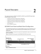
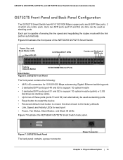
...Front-Panel and Back-Panel Configuration The GS752TS Smart Switch has 48 10/100/1000 Mbps copper ports and 6 SFP fiber ports, 2 of the NETGEAR GS752TS Smart Switch. GS752TS Front Panel The front panel contains the following: • 48 RJ-45 connectors for 10/100/1000 Mbps autosensing Gigabit ...and 50) to support 1G optical module • 2 dedicated SFP ports (port 51 and 52) to support 1G optical module (uplink) or 2.5G stacking (via stacking cable). • Up to two of sensing the line speed and negotiating the duplex mode with the link partner automatically. Each port is capable of...
...Front-Panel and Back-Panel Configuration The GS752TS Smart Switch has 48 10/100/1000 Mbps copper ports and 6 SFP fiber ports, 2 of the NETGEAR GS752TS Smart Switch. GS752TS Front Panel The front panel contains the following: • 48 RJ-45 connectors for 10/100/1000 Mbps autosensing Gigabit ...and 50) to support 1G optical module • 2 dedicated SFP ports (port 51 and 52) to support 1G optical module (uplink) or 2.5G stacking (via stacking cable). • Up to two of sensing the line speed and negotiating the duplex mode with the link partner automatically. Each port is capable of...
GS7xxTS-TPS Hardware Installation Guide
Page 16
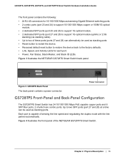
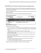
...-Panel Configuration The GS752TPS Smart Switch has 48 10/100/1000 Mbps PoE capable copper ports and 6 SFP fiber ports, 2 of the NETGEAR GS752TPS Smart Switch. GS752TPS Front Panel The front panel contains the following: • 48 RJ-45 connectors for each port. • Power, ...Fan Status, Stack Master, LED mode, PoE Max, and Stack ID LEDs. Figure 9 illustrates the NETGEAR GS752TPS Smart Switch back panel. 16 | Chapter 2. Up to the factory defaults • Link, Speed, and Activity ...
...-Panel Configuration The GS752TPS Smart Switch has 48 10/100/1000 Mbps PoE capable copper ports and 6 SFP fiber ports, 2 of the NETGEAR GS752TPS Smart Switch. GS752TPS Front Panel The front panel contains the following: • 48 RJ-45 connectors for each port. • Power, ...Fan Status, Stack Master, LED mode, PoE Max, and Stack ID LEDs. Figure 9 illustrates the NETGEAR GS752TPS Smart Switch back panel. 16 | Chapter 2. Up to the factory defaults • Link, Speed, and Activity ...

GS7xxTS-TPS Hardware Installation Guide
Page 18
...GS728TPS, GS752TS, and GS752TPS Smart Switch Hardware Installation Guide SFP Port LEDs The following table describes the system LED designations. LED Power Fan Stack Master LED Stack ID Designation • Solid Green - Device is powered on the port at 1000/2500Mbps. Fan has experienced a fail. • Off... System LEDs The following table describes the dedicated SFP port LED designations. Power is booting up and running. • Solid Yellow - Displays the stack ID, from 1 to the device • Solid Yellow - The port is up . • Off - Each SFP port has its own...
...GS728TPS, GS752TS, and GS752TPS Smart Switch Hardware Installation Guide SFP Port LEDs The following table describes the system LED designations. LED Power Fan Stack Master LED Stack ID Designation • Solid Green - Device is powered on the port at 1000/2500Mbps. Fan has experienced a fail. • Off... System LEDs The following table describes the dedicated SFP port LED designations. Power is booting up and running. • Solid Yellow - Displays the stack ID, from 1 to the device • Solid Yellow - The port is up . • Off - Each SFP port has its own...
GS7xxTS-TPS Hardware Installation Guide
Page 19
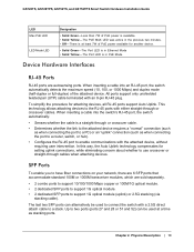
... cables. To simplify the procedure for setting uplink connections, while eliminating concern about whether to a PC) or an "uplink" connection (such as stacking ports. In this way, the Auto Uplink technology compensates for attaching devices, all RJ-45 ports support Auto Uplink. Up to... accommodate standard 100M or 1000M transceiver modules, which are autosensing ports. SFP Ports To enable you to support 1G optical module (uplink) or 2.5G stacking (via stacking cable). Chapter 2. The PoE MAX LED was active in PoE Mode. There is at a time as when connecting the port to a router, ...
... cables. To simplify the procedure for setting uplink connections, while eliminating concern about whether to a PC) or an "uplink" connection (such as stacking ports. In this way, the Auto Uplink technology compensates for attaching devices, all RJ-45 ports support Auto Uplink. Up to... accommodate standard 100M or 1000M transceiver modules, which are autosensing ports. SFP Ports To enable you to support 1G optical module (uplink) or 2.5G stacking (via stacking cable). Chapter 2. The PoE MAX LED was active in PoE Mode. There is at a time as when connecting the port to a router, ...

GS7xxTS-TPS Hardware Installation Guide
Page 20
... be used as a paper clip into the opening to its Power On Self Test (POST). To operate the Factory Defaults button, insert a device such as a stacking cable. This action is equivalent to manually reboot the switch. The last saved configuration is sold separately. When you can remove the current configuration and...
... be used as a paper clip into the opening to its Power On Self Test (POST). To operate the Factory Defaults button, insert a device such as a stacking cable. This action is equivalent to manually reboot the switch. The last saved configuration is sold separately. When you can remove the current configuration and...
GS7xxTS-TPS Hardware Installation Guide
Page 22
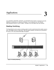
... Smart Switch can be used as your network connections. Applications 3 Your GS728TS, GS728TPS, GS752TS, and GS752TPS Smart Switch is designed to a file server. Power Fan Stack Master ID Link/Act Mode - 1 2 3 4 5 6 7 8 9 10 11 12 Green=Link at 1G Yellow=Link at 10/ 100M 13 14 15 16 17 18 19 20...
... Smart Switch can be used as your network connections. Applications 3 Your GS728TS, GS728TPS, GS752TS, and GS752TPS Smart Switch is designed to a file server. Power Fan Stack Master ID Link/Act Mode - 1 2 3 4 5 6 7 8 9 10 11 12 Green=Link at 1G Yellow=Link at 10/ 100M 13 14 15 16 17 18 19 20...

GS7xxTS-TPS Hardware Installation Guide
Page 23
... a backbone switch in a small network that gives users high-speed access to servers and other network devices. Backbone Switching ` ` ` Chapter 3. Applications | 23 GS752TS Power Fan Stack Master ID Link/Act Mode - 1 2 3 4 5 6 7 8 9 10 11 12 Green=Link at 1G Yellow=Link at 10/ 100M 13 14 15 16 17 18 19 20...
... a backbone switch in a small network that gives users high-speed access to servers and other network devices. Backbone Switching ` ` ` Chapter 3. Applications | 23 GS752TS Power Fan Stack Master ID Link/Act Mode - 1 2 3 4 5 6 7 8 9 10 11 12 Green=Link at 1G Yellow=Link at 10/ 100M 13 14 15 16 17 18 19 20...
GS7xxTS-TPS Hardware Installation Guide
Page 24
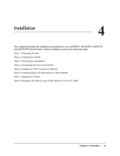
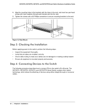
Installation | 24 Installation 4 This chapter describes the installation procedures for your GS728TS, GS728TPS, GS752TS, and GS752TPS Smart Switch. 4. Switch installation involves the following steps: Step 1: Preparing the Site Step 2: Installing the Switch Step 3: Checking the Installation Step 4: Connecting Devices to the Switch Step 5: Installing an SFP Transceiver Module Step 6: Installing Device as Stand-alone or Stack Master Step 7: Applying AC Power Step 8: Managing the Switch using a Web Browser or the PC Utility Chapter 4.
Installation | 24 Installation 4 This chapter describes the installation procedures for your GS728TS, GS728TPS, GS752TS, and GS752TPS Smart Switch. 4. Switch installation involves the following steps: Step 1: Preparing the Site Step 2: Installing the Switch Step 3: Checking the Installation Step 4: Connecting Devices to the Switch Step 5: Installing an SFP Transceiver Module Step 6: Installing Device as Stand-alone or Stack Master Step 7: Applying AC Power Step 8: Managing the Switch using a Web Browser or the PC Utility Chapter 4.

GS7xxTS-TPS Hardware Installation Guide
Page 25
...-panel RJ-45 ports, view the front-panel LEDs, and access the power connector. Environmental • Temperature - The rackmount kit supplied with ambient temperature between stacked switches. Keep the switch away from nearest source of electromagnetic noise, such as direct sunlight, warm air exhausts, hot-air vents, and heaters. • Operating...
...-panel RJ-45 ports, view the front-panel LEDs, and access the power connector. Environmental • Temperature - The rackmount kit supplied with ambient temperature between stacked switches. Keep the switch away from nearest source of electromagnetic noise, such as direct sunlight, warm air exhausts, hot-air vents, and heaters. • Operating...
GS7xxTS-TPS Hardware Installation Guide
Page 26
... not damaged or creating a safety hazard. • Ensure all cables are installed correctly. • Check cable routing to the switch's RJ-45 ports. Power Fan Stack Master Reset Link/Act Mode YGerlleoewn==LLiinnkk at at 1G 10/ - 1 2 3 4 5 6 ID 100M 78 9 10 11 12 DFeafcatuolrtys 13 14 15 16 17 18 19...
... not damaged or creating a safety hazard. • Ensure all cables are installed correctly. • Check cable routing to the switch's RJ-45 ports. Power Fan Stack Master Reset Link/Act Mode YGerlleoewn==LLiinnkk at at 1G 10/ - 1 2 3 4 5 6 ID 100M 78 9 10 11 12 DFeafcatuolrtys 13 14 15 16 17 18 19...
GS7xxTS-TPS Hardware Installation Guide
Page 27
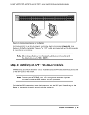
... each PC to install an optional SFP transceiver module into the SFP port. Note: Contact your NETGEAR sales office to make these modules. GS728TS, GS728TPS, GS752TS, and GS752TPS Smart Switch Hardware Installation Guide Power Fan Stack Master ID Link/Act Mode - 1 2 3 4 5 6 7 8 9 10 11 12 Green=Link at 1G Yellow=Link at 10...
... each PC to install an optional SFP transceiver module into the SFP port. Note: Contact your NETGEAR sales office to make these modules. GS728TS, GS728TPS, GS752TS, and GS752TPS Smart Switch Hardware Installation Guide Power Fan Stack Master ID Link/Act Mode - 1 2 3 4 5 6 7 8 9 10 11 12 Green=Link at 1G Yellow=Link at 10...