Manual
Page 2
......2 INTRODUCTION 2 USING THIS MANUAL 2 SYSTEM FEATURES 3 ENCORE I RECEIVER 4 WHT HANDHELD MICROPHONE TRANSMITTER 7 WLT LAVALIER/LAPEL OR HEADWORN MICROPHONE BODYPACK TRANSMITTER 9 WGT INSTRUMENT BODYPACK TRANSMITTER 11 SPECIFICATIONS 13 SERVICE INFORMATION 14 WARRANTY 15 INTRODUCTION Thank you for choosing the Nady Encore I . 2 This manual should answer any questions you will be very pleased with top professional operating features and is the best performance and price value...
......2 INTRODUCTION 2 USING THIS MANUAL 2 SYSTEM FEATURES 3 ENCORE I RECEIVER 4 WHT HANDHELD MICROPHONE TRANSMITTER 7 WLT LAVALIER/LAPEL OR HEADWORN MICROPHONE BODYPACK TRANSMITTER 9 WGT INSTRUMENT BODYPACK TRANSMITTER 11 SPECIFICATIONS 13 SERVICE INFORMATION 14 WARRANTY 15 INTRODUCTION Thank you for choosing the Nady Encore I . 2 This manual should answer any questions you will be very pleased with top professional operating features and is the best performance and price value...
Manual
Page 3
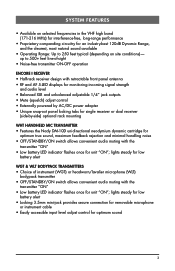
... unit "ON"; lights steady for low battery alert WGT & WLT BODYPACK TRANSMITTERS • Choice of -sight • Noise-free transmitter ON-OFF operation ENCORE I RECEIVER • Half-rack receiver design with retractable front panel antenna • RF and AF 5-LED displays for monitoring incoming signal strength and audio level • Balanced XLR and unbalanced adjustable 1/4" jack outputs • Mute (squelch) adjust control • Externally powered by AC/DC power adapter • Unique...
... unit "ON"; lights steady for low battery alert WGT & WLT BODYPACK TRANSMITTERS • Choice of -sight • Noise-free transmitter ON-OFF operation ENCORE I RECEIVER • Half-rack receiver design with retractable front panel antenna • RF and AF 5-LED displays for monitoring incoming signal strength and audio level • Balanced XLR and unbalanced adjustable 1/4" jack outputs • Mute (squelch) adjust control • Externally powered by AC/DC power adapter • Unique...
Manual
Page 4
...) Adjustment In normal operation, the MUTE CONTROL (2) should be extended fully to turn on the back of the receiver (as it is always best to the factory preset minimum RF level. Turning the squelch control too far clockwise will only light when the system transmitter is supplied with a TELESCOPIC ANTENNA (16). Always ensure adequate airflow and heat dissipation in areas of the Encore I RECEIVER 1. The POWER...
...) Adjustment In normal operation, the MUTE CONTROL (2) should be extended fully to turn on the back of the receiver (as it is always best to the factory preset minimum RF level. Turning the squelch control too far clockwise will only light when the system transmitter is supplied with a TELESCOPIC ANTENNA (16). Always ensure adequate airflow and heat dissipation in areas of the Encore I RECEIVER 1. The POWER...
Manual
Page 5
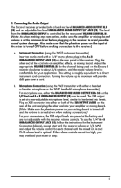
... the BALANCED MIC AUDIO OUTPUT XLRs (14) or the 1/4" line level A + B UNBALANCED OUTPUT (13) can be used on the Encore I receiver provides both of the XLR OUTPUT JACKS on the rear panel of the cord into an amplifier, effects, or mixing board. Turning the volume up to a direct instrument cord connection. Adjust the appropriate VOLUME CONTROL (6) for your mixer or amp. 5 b. If the volume controls are not adjustable with a 1/4" mono phone plug in the receiver to hardwired mic levels. This setting is set...
... the BALANCED MIC AUDIO OUTPUT XLRs (14) or the 1/4" line level A + B UNBALANCED OUTPUT (13) can be used on the Encore I receiver provides both of the XLR OUTPUT JACKS on the rear panel of the cord into an amplifier, effects, or mixing board. Turning the volume up to a direct instrument cord connection. Adjust the appropriate VOLUME CONTROL (6) for your mixer or amp. 5 b. If the volume controls are not adjustable with a 1/4" mono phone plug in the receiver to hardwired mic levels. This setting is set...

Manual
Page 6
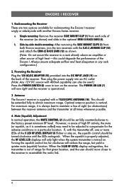
16 7 8 45 12-15V UNBALANCED OUT DC INPUT VOLUME BALANCED OUT MUTE 13 11 6 14 2 15 9 12 10 6 1 9 1 12
16 7 8 45 12-15V UNBALANCED OUT DC INPUT VOLUME BALANCED OUT MUTE 13 11 6 14 2 15 9 12 10 6 1 9 1 12
Manual
Page 7
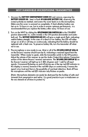
... the Audio Output Microphone Connection section of the above Encore I receiver instructions. Occasional flickering on continuously, it .] 7 It is the possibility of salts and minerals from the microphone until the red LED indicator only flickers on ). WHT HANDHELD MICROPHONE TRANSMITTER 1. To preserve battery life, turn the transmitter off when not in this display is screwed on the Encore I receiver will give a single quick flash, indicating...
... the Audio Output Microphone Connection section of the above Encore I receiver instructions. Occasional flickering on continuously, it .] 7 It is the possibility of salts and minerals from the microphone until the red LED indicator only flickers on ). WHT HANDHELD MICROPHONE TRANSMITTER 1. To preserve battery life, turn the transmitter off when not in this display is screwed on the Encore I receiver will give a single quick flash, indicating...
Manual
Page 9
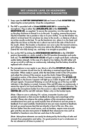
... the Audio Output Microphone Connection section of the top red LED indicator in selecting P.A. Do not place too close -source mics such as handheld or headworn mics that the battery should now be destroyed by sliding the OFF/STANDBY/ON SWITCH (27) to the ON position and adjust the volume of the receiver as possible.) 3. To use the lavalier mic, attach it .) 9 Most or all directions and...
... the Audio Output Microphone Connection section of the top red LED indicator in selecting P.A. Do not place too close -source mics such as handheld or headworn mics that the battery should now be destroyed by sliding the OFF/STANDBY/ON SWITCH (27) to the ON position and adjust the volume of the receiver as possible.) 3. To use the lavalier mic, attach it .) 9 Most or all directions and...

Manual
Page 10
24 29 28 27 LOW MIC BAT HI OFF/STANDBY/ON 22 25 26 22 Opening Battery Compartment 23 10
24 29 28 27 LOW MIC BAT HI OFF/STANDBY/ON 22 25 26 22 Opening Battery Compartment 23 10
Manual
Page 11
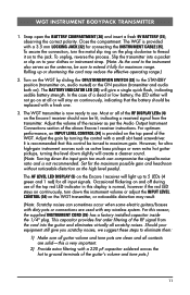
.... Adjust the volume of the receiver as per the Audio Output Instrument Connections section of the above Encore I receiver will give you scratchy noises, we suggest these steps to use of the WGT. For optimum performance, an INPUT LEVEL CONTROL (34) is provided on ). Occasional flickering on and off during use . For this control be replaced with a 3.5 mm LOCKING JACK (32) for ultra high-gain instrument sources...
.... Adjust the volume of the receiver as per the Audio Output Instrument Connections section of the above Encore I receiver will give you scratchy noises, we suggest these steps to use of the WGT. For optimum performance, an INPUT LEVEL CONTROL (34) is provided on ). Occasional flickering on and off during use . For this control be replaced with a 3.5 mm LOCKING JACK (32) for ultra high-gain instrument sources...
Manual
Page 13
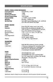
...) 6.9 oz (193 g) 3.6 oz (101 g) Specifications subject to change at any time without prior notice for connecting to omni or unidirectional lavalier mic or unidirectional head worn mic, with phantom power (WLT); SPECIFICATIONS ENCORE I RECEIVER Controls Connectors LED Indicators Dimensions (Max.) Weight Power Requirements Antenna Power ON/OFF, volume control, mute control Balanced XLR and unbalanced adjustable 1/4" audio out jacks, 2.1 mm barrel-type DC input jack Power ON, 5-LED RF & AF level displays , 1.75" x 7.5" x 8.1" (4.4 x 19 x 20.7 cm...
...) 6.9 oz (193 g) 3.6 oz (101 g) Specifications subject to change at any time without prior notice for connecting to omni or unidirectional lavalier mic or unidirectional head worn mic, with phantom power (WLT); SPECIFICATIONS ENCORE I RECEIVER Controls Connectors LED Indicators Dimensions (Max.) Weight Power Requirements Antenna Power ON/OFF, volume control, mute control Balanced XLR and unbalanced adjustable 1/4" audio out jacks, 2.1 mm barrel-type DC input jack Power ON, 5-LED RF & AF level displays , 1.75" x 7.5" x 8.1" (4.4 x 19 x 20.7 cm...

Manual
Page 14
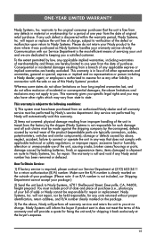
... also void the warranty. 14 For service of a unit under warranty, please follow the instructions in your system, please refer to the Support page at (510) 652-2411 to obtain a Return Authorization (R/A) Number and service quote (if out of the package that you are returning. Do not attempt to : Nady Systems, Service Department, 6701 Shellmound Street, Emeryville...
... also void the warranty. 14 For service of a unit under warranty, please follow the instructions in your system, please refer to the Support page at (510) 652-2411 to obtain a Return Authorization (R/A) Number and service quote (if out of the package that you are returning. Do not attempt to : Nady Systems, Service Department, 6701 Shellmound Street, Emeryville...
Manual
Page 15
... is in material or workmanship for repair or replacement. damage caused by Nady's service department. items damaged in connection with applicable technical or safety regulations, or improper repair, excessive heat or humidity, alteration or unreasonable use of this Nady Systems' product. Make sure the R/A number is clearly marked on the outside of all warranty service and return the unit to...
... is in material or workmanship for repair or replacement. damage caused by Nady's service department. items damaged in connection with applicable technical or safety regulations, or improper repair, excessive heat or humidity, alteration or unreasonable use of this Nady Systems' product. Make sure the R/A number is clearly marked on the outside of all warranty service and return the unit to...
Manual
Page 16
The device complies with RSS-210 of Industry & Science Canada. Nady Wireless Systems are type accepted under FCC rules parts 90, 74 and 15. Operation is subject to the following two conditions: (1) this device may not cause harmful interference and (2) this device must accept any interference received, including interference that may cause undesired operation. 6701 Shellmound Street | Emeryville, CA USA 94608 T 510.652.2411 | F 510.652.5075 | www.nady.com
The device complies with RSS-210 of Industry & Science Canada. Nady Wireless Systems are type accepted under FCC rules parts 90, 74 and 15. Operation is subject to the following two conditions: (1) this device may not cause harmful interference and (2) this device must accept any interference received, including interference that may cause undesired operation. 6701 Shellmound Street | Emeryville, CA USA 94608 T 510.652.2411 | F 510.652.5075 | www.nady.com


