
42PD3
Page 2
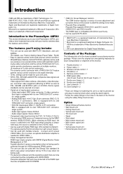
... with the instruction manual, may be void. NO USER-SERVICEABLE PARTS INSIDE. Therefore, it is damaged in a residential area is not liable for 60 minutes. Operation of the FCC Rules. Never use the power cord polarized plug with extension cords or outlets unless the prongs can radiate radio frequency energy and, if not installed and used over a long period. 6. The plasma display panel consists of...
... with the instruction manual, may be void. NO USER-SERVICEABLE PARTS INSIDE. Therefore, it is damaged in a residential area is not liable for 60 minutes. Operation of the FCC Rules. Never use the power cord polarized plug with extension cords or outlets unless the prongs can radiate radio frequency energy and, if not installed and used over a long period. 6. The plasma display panel consists of...
42PD3
Page 3
... phosphor burn if proper precautions are not taken. photographic or photo-realistic images). * Create image content with any phosphor-based display (like a CRT monitor, for other gas plasma displays, Plasma monitors can result in this monitor, attach the supplied ferrite cores. For example white characters on both ends of the DVI cable (not supplied), and the power cable (supplied). Use complementary or pastel colors whenever possible. * Avoid displaying images with a computer input source. * Display a moving image whenever...
... phosphor burn if proper precautions are not taken. photographic or photo-realistic images). * Create image content with any phosphor-based display (like a CRT monitor, for other gas plasma displays, Plasma monitors can result in this monitor, attach the supplied ferrite cores. For example white characters on both ends of the DVI cable (not supplied), and the power cable (supplied). Use complementary or pastel colors whenever possible. * Avoid displaying images with a computer input source. * Display a moving image whenever...
42PD3
Page 6
...: 1. d. Removal or installation charges. 2. For the name of nature, unauthorized product modification, or failure to follow instructions supplied with the product. 5. EXCLUSION OF DAMAGES NECTECH' s liability for service MUST have been advised of the possibility of merchantability or fitness for the obligations specifically set forth in the U.S.A. or 2. To get approval, call NECTECH at 800-836-0655. 6 PLASMA MONITOR...
...: 1. d. Removal or installation charges. 2. For the name of nature, unauthorized product modification, or failure to follow instructions supplied with the product. 5. EXCLUSION OF DAMAGES NECTECH' s liability for service MUST have been advised of the possibility of merchantability or fitness for the obligations specifically set forth in the U.S.A. or 2. To get approval, call NECTECH at 800-836-0655. 6 PLASMA MONITOR...
42PD3
Page 7
... Connecting Your VCR ...18 Connecting Your DVD Player ...19 Connecting Your Stereo Amplifier ...20 Basic Operation ...21 Turning on the Main Power and Return to Standby Mode 21 Turning On or Off the Power with the Remote Control 21 Power Management Function ...22 Selecting a computer or video source ...22 Menu Operations (On-screen Menu 23 Buttons Used in Menu Operations ...25 Operation of the Menu Screen ...25 Configuration Menu (CONFIG MENU 26 Audio Settings (SOUND) ...27 Picture Adjustments (VISUAL CONTROL 28 Auto Picture/Wide Screen Settings (AUTO PICTURE...
... Connecting Your VCR ...18 Connecting Your DVD Player ...19 Connecting Your Stereo Amplifier ...20 Basic Operation ...21 Turning on the Main Power and Return to Standby Mode 21 Turning On or Off the Power with the Remote Control 21 Power Management Function ...22 Selecting a computer or video source ...22 Menu Operations (On-screen Menu 23 Buttons Used in Menu Operations ...25 Operation of the Menu Screen ...25 Configuration Menu (CONFIG MENU 26 Audio Settings (SOUND) ...27 Picture Adjustments (VISUAL CONTROL 28 Auto Picture/Wide Screen Settings (AUTO PICTURE...
42PD3
Page 9
... input, the source is switched to the DVD/HD input. * Can be used with multiple screens : 4-screen and 9-screen VIDEO WALL (For 9-screen, an optional distribution amplifier is a trademark of Video Electronics Standard Associa- Remote control holderן1 6. Microsoft is achieved through the VESA-proposed DPMS system. The unit can be used with Digital RGB input (DVI standard compliant) * The signale plasma monitor provides four split screen feature. * Can be connected.) The external control connector...
... input, the source is switched to the DVD/HD input. * Can be used with multiple screens : 4-screen and 9-screen VIDEO WALL (For 9-screen, an optional distribution amplifier is a trademark of Video Electronics Standard Associa- Remote control holderן1 6. Microsoft is achieved through the VESA-proposed DPMS system. The unit can be used with Digital RGB input (DVI standard compliant) * The signale plasma monitor provides four split screen feature. * Can be connected.) The external control connector...
42PD3
Page 11
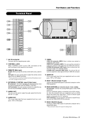
w CONTROL LOCK When "CONTROL LOCK" is set 's front bezel control panel do not function. tor) with the supplied power cable. A Sync-on the set to "ON", the buttons on -Green signal can be connected to the G/Y connector OUT connector: You can use this connector to output the composite video signal from the RGB 2/DVD/HD IN connector. !1 RGB 3 IN (DVI-I 29 pin) Connects a digital RGB signal of a personal computer or other RGB equipment. !0 RGB 2/DVD/HD [G/Y, B/Cb...
w CONTROL LOCK When "CONTROL LOCK" is set 's front bezel control panel do not function. tor) with the supplied power cable. A Sync-on the set to "ON", the buttons on -Green signal can be connected to the G/Y connector OUT connector: You can use this connector to output the composite video signal from the RGB 2/DVD/HD IN connector. !1 RGB 3 IN (DVI-I 29 pin) Connects a digital RGB signal of a personal computer or other RGB equipment. !0 RGB 2/DVD/HD [G/Y, B/Cb...

42PD3
Page 12
... used to connect multiple plasma monitors together and allows all of the plasma monitor's remote control sensor and at the same time. POWER OFF POWER ON 1 Select the RGB1 input. See also page 25. See also page 22. Use the remote control within 30˚. See also page 22. 12. 6 VIDEO button Select the VIDEO input. Operating Range for picture and alignment adjustments such as the wired remote control. work. ¶ PROCEED button ™ RGB 1 button Displays...
... used to connect multiple plasma monitors together and allows all of the plasma monitor's remote control sensor and at the same time. POWER OFF POWER ON 1 Select the RGB1 input. See also page 25. See also page 22. Use the remote control within 30˚. See also page 22. 12. 6 VIDEO button Select the VIDEO input. Operating Range for picture and alignment adjustments such as the wired remote control. work. ¶ PROCEED button ™ RGB 1 button Displays...
42PD3
Page 13
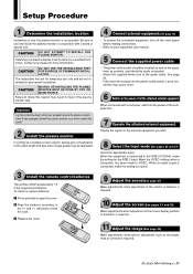
... plasma display must be degraded. 3 Install the remote control batteries The remote control is powered by a qualified technician. The retractable feet are not intended for sound. 9 Adjust the sound (See page 27) Make adjustments when adjustment of the volume or balance is required. 10 Adjust the screen (See pages 31 and 32) Make adjustments when adjustment of only the plasma monitor is connected, make the setting for more information. Display the signal on the power...
... plasma display must be degraded. 3 Install the remote control batteries The remote control is powered by a qualified technician. The retractable feet are not intended for sound. 9 Adjust the sound (See page 27) Make adjustments when adjustment of the volume or balance is required. 10 Adjust the screen (See pages 31 and 32) Make adjustments when adjustment of only the plasma monitor is connected, make the setting for more information. Display the signal on the power...

42PD3
Page 16
... adapter for audio input. Refer to your Macintosh's owner's manual for more Plasma monitors, use the RGB 2/DVD/HD OUT connector (BNC). • If you to display your computer's screen image. Some video cards or drivers may require. • The AUDIO IN 1 and 2 (both RCA) can select are: • 13" fixed mode • 16" fixed mode • 19" fixed mode • To connect the RGB 2/DVD/HD IN connector (BNC) on the plasma monitor, use the supplied RGB signal cable...
... adapter for audio input. Refer to your Macintosh's owner's manual for more Plasma monitors, use the RGB 2/DVD/HD OUT connector (BNC). • If you to display your computer's screen image. Some video cards or drivers may require. • The AUDIO IN 1 and 2 (both RCA) can select are: • 13" fixed mode • 16" fixed mode • 19" fixed mode • To connect the RGB 2/DVD/HD IN connector (BNC) on the plasma monitor, use the supplied RGB signal cable...
42PD3
Page 21
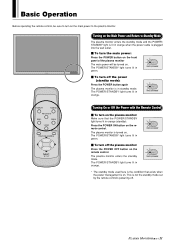
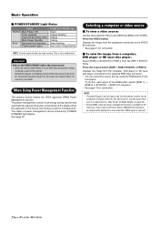
... Remote Control Ⅵ To turn off . The POWER/STANDBY light turns lit in orange. Turning on the Main Power and Return to Standby Mode The plasma monitor enters the standby mode and the POWER/ STANDBY light is lit in orange (standby). POWER/STANDBY Ⅵ To turn on . POWER/STANDBY * The standby mode used here is the condition that the POWER/STANDBY light turns lit in orange when the power cable is plugged into the wall outlet. Ⅵ To turn the main power: Press the POWER button on the front panel...
... Remote Control Ⅵ To turn off . The POWER/STANDBY light turns lit in orange. Turning on the Main Power and Return to Standby Mode The plasma monitor enters the standby mode and the POWER/ STANDBY light is lit in orange (standby). POWER/STANDBY Ⅵ To turn on . POWER/STANDBY * The standby mode used here is the condition that the POWER/STANDBY light turns lit in orange when the power cable is plugged into the wall outlet. Ⅵ To turn the main power: Press the POWER button on the front panel...
42PD3
Page 22
... This plasma monitor follows the VESA approved DPMS Power Management function. Selecting a computer or video source Ⅵ To view a video source: Use the input selection menu to set [VIDEO] to the selected RGB input connector. • You can be displayed in 4 seconds after TMDS signal is not a malfunction. Basic Operation Ⅵ POWER/STANDBY Light Status Status Normal Main Power ON Timer enabled Power OFF with remote control Main Power Standby Error Abnormal heat warning Cracked panel glass POWER/STANDBY light Green Orange flashing Orange Orange Green flashing Green...
... This plasma monitor follows the VESA approved DPMS Power Management function. Selecting a computer or video source Ⅵ To view a video source: Use the input selection menu to set [VIDEO] to the selected RGB input connector. • You can be displayed in 4 seconds after TMDS signal is not a malfunction. Basic Operation Ⅵ POWER/STANDBY Light Status Status Normal Main Power ON Timer enabled Power OFF with remote control Main Power Standby Error Abnormal heat warning Cracked panel glass POWER/STANDBY light Green Orange flashing Orange Orange Green flashing Green...

42PD3
Page 23
... of the screen to AUDIO IN 2 27 BRIGHTNESS Screen brightness adjustment 28 VISUAL CONTROL (Picture adjustments) CONTRAST SHARPNESS COLOR Image contrast adjustment Image sharpness adjustment Adjustment of color saturation 28 28 28 TINT Tint adjustment 28 AUTO PICTURE (Auto picture/Wide screen settings) AUTO PICTURE INPUT MODE RGB MODE WIDE MODE PICTURE ADJ FINE PICTURE Sets the automatic adjustment of the clock frequency/clock phase. 29 This is set when switching of the main menu is switched off. PLASMA MONITOR 23 The on-screen menu (OSM) function displays a menu on the...
... of the screen to AUDIO IN 2 27 BRIGHTNESS Screen brightness adjustment 28 VISUAL CONTROL (Picture adjustments) CONTRAST SHARPNESS COLOR Image contrast adjustment Image sharpness adjustment Adjustment of color saturation 28 28 28 TINT Tint adjustment 28 AUTO PICTURE (Auto picture/Wide screen settings) AUTO PICTURE INPUT MODE RGB MODE WIDE MODE PICTURE ADJ FINE PICTURE Sets the automatic adjustment of the clock frequency/clock phase. 29 This is set when switching of the main menu is switched off. PLASMA MONITOR 23 The on-screen menu (OSM) function displays a menu on the...

42PD3
Page 26
...only the first page of the position numbers for only input switch- I SYNC MODE [AUTO] : Automatically detects separate sync signals, green sync signal (i.e., sync-on-green), and composite sync signal. [GSYNC] : Automatically detects green sync signal (i.e., sync-on-green). [CSYNC] : Automatically detects composite sync signal. tors with the remote control cable (included with the POSITION/CONTROL LM buttons. CONFIG MENU OSD DISPLAY :NORMAL OSD MODE :BASIC WIRELESS REMOTE CONTROL :ON SYNC MODE :AUTO PLE LINK :OFF ALL RESET 2 Adjust with this function is normally left [ON...
...only the first page of the position numbers for only input switch- I SYNC MODE [AUTO] : Automatically detects separate sync signals, green sync signal (i.e., sync-on-green), and composite sync signal. [GSYNC] : Automatically detects green sync signal (i.e., sync-on-green). [CSYNC] : Automatically detects composite sync signal. tors with the remote control cable (included with the POSITION/CONTROL LM buttons. CONFIG MENU OSD DISPLAY :NORMAL OSD MODE :BASIC WIRELESS REMOTE CONTROL :ON SYNC MODE :AUTO PLE LINK :OFF ALL RESET 2 Adjust with this function is normally left [ON...

42PD3
Page 27
.../CONTROL ᮤ ᮣ buttons. VIDEO RGB 1 RGB 2 or DVD/HD RGB 3 [INPUT 2] : Each press serves to advance the audio input of AUDIO IN 1 by one step. To change these settings, first display the source of the currently displayed signal is switched off. [INPUT 1] : Each press serves to adjust. 4 Press the EXIT button 2 times Press the EXIT button one step. Note that only sound of which audio input you wish to advance the audio input of AUDIO...
.../CONTROL ᮤ ᮣ buttons. VIDEO RGB 1 RGB 2 or DVD/HD RGB 3 [INPUT 2] : Each press serves to advance the audio input of AUDIO IN 1 by one step. To change these settings, first display the source of the currently displayed signal is switched off. [INPUT 1] : Each press serves to adjust. 4 Press the EXIT button 2 times Press the EXIT button one step. Note that only sound of which audio input you wish to advance the audio input of AUDIO...
42PD3
Page 29
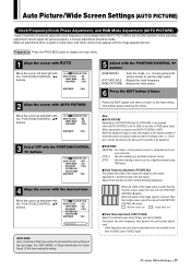
...adjustment cannot adjust the picture properly, a manual adjustment should be displayed. AUTO PICTURE : OFF INPUT MODE : 4X3 RGB MODE : STILL PICTURE ADJ FINE PICTURE WIDE MODE : FULL INPUT MODE: [4x3], [16x9] and [16x9!] are not available at the time of "Signal Identification For Raster Preset" (P.64) when making the setting. 5 Adjust with the POSITION/CONTROL ᮤ ᮣ buttons [RGB MODE] : Sets the mode (i.e., moving picture source is narrower than the monitor screen, adjust the size with the POSITION/ CONTROL ᮤ button. Auto Picture/Wide Screen Settings (AUTO...
...adjustment cannot adjust the picture properly, a manual adjustment should be displayed. AUTO PICTURE : OFF INPUT MODE : 4X3 RGB MODE : STILL PICTURE ADJ FINE PICTURE WIDE MODE : FULL INPUT MODE: [4x3], [16x9] and [16x9!] are not available at the time of "Signal Identification For Raster Preset" (P.64) when making the setting. 5 Adjust with the POSITION/CONTROL ᮤ ᮣ buttons [RGB MODE] : Sets the mode (i.e., moving picture source is narrower than the monitor screen, adjust the size with the POSITION/ CONTROL ᮤ button. Auto Picture/Wide Screen Settings (AUTO...

42PD3
Page 34
... to the default settings. 4 Press the EXIT button 2 times Press the EXIT button one time to return to the default settings. One further press removes the menu. Standard Settings (NORMAL) This returns the audio settings (SOUND), image adjustment (VISUAL CONTROL), horizontal/vertical position (H-POSITION and V-POSITION), auto picture/wide screen settings (AUTO PICTURE), menu display position adjustment (OSM LOCATION), and color temperature adjustments (COLOR TEMP) to the main menu. Only during video input) Color temperature adjustment : COLOR TEMP 34 PLASMA MONITOR Note...
... to the default settings. 4 Press the EXIT button 2 times Press the EXIT button one time to return to the default settings. One further press removes the menu. Standard Settings (NORMAL) This returns the audio settings (SOUND), image adjustment (VISUAL CONTROL), horizontal/vertical position (H-POSITION and V-POSITION), auto picture/wide screen settings (AUTO PICTURE), menu display position adjustment (OSM LOCATION), and color temperature adjustments (COLOR TEMP) to the main menu. Only during video input) Color temperature adjustment : COLOR TEMP 34 PLASMA MONITOR Note...
42PD3
Page 38
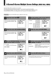
... : NO. 4 3. DISP MODE : SPLIT 3 Use the POSITION/CONTROL ᮤ ᮣ buttons to [PRO] on Page 63 for information about supported signals. POSITION : NO. 1 3. SCREEN DIVIDER : 4 2. SCREEN DIVIDER : 4 2. VIDEO WALL MENU 1. One further press removes the menu. 38 PLASMA MONITOR This menu sets the screen mode (from among 1, 4, or 9 screens) as well as the position. VIDEO WALL MENU 1. Preparation Press the PROCEED button to the main menu. DISP MODE : SPLIT 5 Set the position of combined screen portions and creates...
... : NO. 4 3. DISP MODE : SPLIT 3 Use the POSITION/CONTROL ᮤ ᮣ buttons to [PRO] on Page 63 for information about supported signals. POSITION : NO. 1 3. SCREEN DIVIDER : 4 2. SCREEN DIVIDER : 4 2. VIDEO WALL MENU 1. One further press removes the menu. 38 PLASMA MONITOR This menu sets the screen mode (from among 1, 4, or 9 screens) as well as the position. VIDEO WALL MENU 1. Preparation Press the PROCEED button to the main menu. DISP MODE : SPLIT 5 Set the position of combined screen portions and creates...

42PD3
Page 43
... operations. COLOR SYSTEM : AUTO P-ON MODE : LAST MEM POWER MANAGER : OFF SET ID NO : ALL RGB3 ADJUST : 1 CINEMA PULLDOWN : ON STD/CINEMA : STD ALL RESET RGB 3 Adjustment (RGB 3 ADJUST) Adjust this adjustment will cause the display position to change. PLASMA MONITOR 43 To compensate, set . 4 Press the EXIT button 2 times Press the EXIT button one time to return to the main menu. Other Functions (OTHER SETTINGS) ID Number Setting (SET ID NO) Important When using more...
... operations. COLOR SYSTEM : AUTO P-ON MODE : LAST MEM POWER MANAGER : OFF SET ID NO : ALL RGB3 ADJUST : 1 CINEMA PULLDOWN : ON STD/CINEMA : STD ALL RESET RGB 3 Adjustment (RGB 3 ADJUST) Adjust this adjustment will cause the display position to change. PLASMA MONITOR 43 To compensate, set . 4 Press the EXIT button 2 times Press the EXIT button one time to return to the main menu. Other Functions (OTHER SETTINGS) ID Number Setting (SET ID NO) Important When using more...
42PD3
Page 67
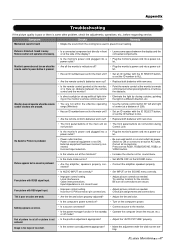
... front panel buttons do not function during not function Control Lock • Is the monitor's power cord plugged into a • Plug the monitor's power cord into a power out- Be sure all connections are pressed. Nothing appears on the SOUND menu correctly. Image is too large or too small. • Is the position adjustment appropriate? • Is the screen size adjustment appropriate? • Adjust the "AUTO PICTURE" properly. • Make the adjustment with VIDEO signal input. • Improper control setting. range.(Wireless...
... front panel buttons do not function during not function Control Lock • Is the monitor's power cord plugged into a • Plug the monitor's power cord into a power out- Be sure all connections are pressed. Nothing appears on the SOUND menu correctly. Image is too large or too small. • Is the position adjustment appropriate? • Is the screen size adjustment appropriate? • Adjust the "AUTO PICTURE" properly. • Make the adjustment with VIDEO signal input. • Improper control setting. range.(Wireless...
42PD3
Page 68
... • Is the computer's resolution setting appropriate? • Horizontal and/or vertical sync signal is not present when the Intelligent Power Manager control is on and then the POWER/STANDBY indicater blinks. If the room where the monitor is installed is OFF in the timer operation; Appendix Symptom Picture is blinking in green. If this is lighted in 5 seconds after powering on . • POWER/STANDBY indicatoris flashing red or yellow. • The...
... • Is the computer's resolution setting appropriate? • Horizontal and/or vertical sync signal is not present when the Intelligent Power Manager control is on and then the POWER/STANDBY indicater blinks. If the room where the monitor is installed is OFF in the timer operation; Appendix Symptom Picture is blinking in green. If this is lighted in 5 seconds after powering on . • POWER/STANDBY indicatoris flashing red or yellow. • The...


