
User Manual
Page 7
... bands, although a single antenna may not be connected to finding the ideal antenna for an AP-5131 or AP-5181 model access point and an AP300 (non-integrated antenna) model access port. Motorola Enterprise Wireless LAN products operate in this guide are designed to two radios at the same time. These ... characteristics that describe how an antenna sends and receives radio frequency signals is critical to radios operating in the 5 GHz band. Wireless devices conforming to the frequency band they support. Using the right antenna in a given environment, some will maximize both . Some...
... bands, although a single antenna may not be connected to finding the ideal antenna for an AP-5131 or AP-5181 model access point and an AP300 (non-integrated antenna) model access port. Motorola Enterprise Wireless LAN products operate in this guide are designed to two radios at the same time. These ... characteristics that describe how an antenna sends and receives radio frequency signals is critical to radios operating in the 5 GHz band. Wireless devices conforming to the frequency band they support. Using the right antenna in a given environment, some will maximize both . Some...

User Manual
Page 8
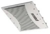
... two sets of Motorola's WLAN product suite. For an AP-5131, there are several different part number configurations unrelated to customize the radiated signal lobes of antenna connectors providing diversity (for each spectrum supported. The connectors on the AP provide dual spectrum capability - NOTE: . 1-2 Enterprise Wireless LAN Antenna Specification Guide 1.1.1 Access Points and Access Ports Supported The...
... two sets of Motorola's WLAN product suite. For an AP-5131, there are several different part number configurations unrelated to customize the radiated signal lobes of antenna connectors providing diversity (for each spectrum supported. The connectors on the AP provide dual spectrum capability - NOTE: . 1-2 Enterprise Wireless LAN Antenna Specification Guide 1.1.1 Access Points and Access Ports Supported The...

User Manual
Page 9
... rather than the center element . Motorola (Symbol) had previously standardized our offerings for access points/ports: • 2.4 GHz is Reverse polarity BNC female (RP-BNC-F) • 5 GHz is reverse polarity SMA female (RP-SMA-F) • Dual Band is "reverse polarity". A male connector is the FCC's requirement for AP-5181). The following displays the connectors used...
... rather than the center element . Motorola (Symbol) had previously standardized our offerings for access points/ports: • 2.4 GHz is Reverse polarity BNC female (RP-BNC-F) • 5 GHz is reverse polarity SMA female (RP-SMA-F) • Dual Band is "reverse polarity". A male connector is the FCC's requirement for AP-5181). The following displays the connectors used...

User Manual
Page 11
Figure 1.5 Type N-F Figure 1.6 Type N-M Antenna Selection and Description 1-5 Additionally, antennas deployed outdoors and industry standard accessories like lightening arrestors use Type-N connectors (as displayed below). Therefore, with the combinations devices required (access points/ports, antennas, cable extensions, and lightening arrestors), various adapter cables are required to connect an antenna to an access point/port.
Figure 1.5 Type N-F Figure 1.6 Type N-M Antenna Selection and Description 1-5 Additionally, antennas deployed outdoors and industry standard accessories like lightening arrestors use Type-N connectors (as displayed below). Therefore, with the combinations devices required (access points/ports, antennas, cable extensions, and lightening arrestors), various adapter cables are required to connect an antenna to an access point/port.
User Manual
Page 13
... out horizontally to the sides of a dipole array is that are not suitable for omni-directional situations. Usually used in point-to-multi-point situations. The advantage of the antenna and equal in a vertical position. This is a directional antenna with the dish, ...1.2 Antenna Selection Criteria In addition to antenna frequency, there is other criteria to consider when selecting an antenna for the AP-5131, AP-5181 or AP300 (non-integrated antenna) model access port. 1.2.1 Antenna Pattern 1.2.1.1 Omni-Directional Signal radiates from the wall. It usually has 2 dBi of gain. 1.2.2.4...
... out horizontally to the sides of a dipole array is that are not suitable for omni-directional situations. Usually used in point-to-multi-point situations. The advantage of the antenna and equal in a vertical position. This is a directional antenna with the dish, ...1.2 Antenna Selection Criteria In addition to antenna frequency, there is other criteria to consider when selecting an antenna for the AP-5131, AP-5181 or AP300 (non-integrated antenna) model access port. 1.2.1 Antenna Pattern 1.2.1.1 Omni-Directional Signal radiates from the wall. It usually has 2 dBi of gain. 1.2.2.4...

User Manual
Page 14
... electrical field which the antenna performs at the point of wireless switches, access ports, access points, client connectivity cards, ruggedized mobile voice/data devices and network management software, as well as wireless mobility planning and deployment services, Motorola offers comprehensive end-to-end wireless enterprise LAN solutions, giving you secure, reliable access to the antenna expressed on the decibel...
... electrical field which the antenna performs at the point of wireless switches, access ports, access points, client connectivity cards, ruggedized mobile voice/data devices and network management software, as well as wireless mobility planning and deployment services, Motorola offers comprehensive end-to-end wireless enterprise LAN solutions, giving you secure, reliable access to the antenna expressed on the decibel...

User Manual
Page 17
... with the antenna you wrote down to confirm that model access port or access point. Follow that column down . • Follow the row antenna across the table to the columns for your AP-5131, AP-5181 or AP300 (non-integrated antenna) deployment: • Find your Motorola access point or access point model at the top of the chart (refer to connect...
... with the antenna you wrote down to confirm that model access port or access point. Follow that column down . • Follow the row antenna across the table to the columns for your AP-5131, AP-5181 or AP300 (non-integrated antenna) deployment: • Find your Motorola access point or access point model at the top of the chart (refer to connect...

User Manual
Page 87
... discussion are descriptions of the single and dual-band antennas supported, their supported connector models and how lightning arrestors are physically connected to an AP-5131 model access point. Conn 1 RSMA-m RSMA-m RSMA-m RSMA-f RSMA-f N-m N-f N-m N-m N-m N-m RPBNC-f N-m N-f N-m N-f N-m N-m N-m Conn 2 RBNC-f N-m N-f bulkhead N-f bulkhead N-m RBNC-m N-f N-m N-m N-m N-m RBNC-m RBNC-m N-f N-m RBNC-f RBNC-f N-m RSMA-m Attn 2.4 Attn 5.5 0.2 N/A 0.2 0.3 0.2 0.3 0.2 0.3 0.2 0.3 1.5 N/A 0.2 0.3 10.6 15.5 2 2.9 2.5 4 4.5 7 2.3 N/A 0.6 N/A 0.24 N/A 0.15 N/A 0.85...
... discussion are descriptions of the single and dual-band antennas supported, their supported connector models and how lightning arrestors are physically connected to an AP-5131 model access point. Conn 1 RSMA-m RSMA-m RSMA-m RSMA-f RSMA-f N-m N-f N-m N-m N-m N-m RPBNC-f N-m N-f N-m N-f N-m N-m N-m Conn 2 RBNC-f N-m N-f bulkhead N-f bulkhead N-m RBNC-m N-f N-m N-m N-m N-m RBNC-m RBNC-m N-f N-m RBNC-f RBNC-f N-m RSMA-m Attn 2.4 Attn 5.5 0.2 N/A 0.2 0.3 0.2 0.3 0.2 0.3 0.2 0.3 1.5 N/A 0.2 0.3 10.6 15.5 2 2.9 2.5 4 4.5 7 2.3 N/A 0.6 N/A 0.24 N/A 0.15 N/A 0.85...

User Manual
Page 89
...-3 10.1.1 RP-BNC Male Antenna Installation Refer to the following for a graphical depiction of the parts and connection options available for cabling an 2.4 GHz AP-5131 model access point using RP-BNC male antennas: Antennas: ML-2499-7PNA2-01R ML-2499-11PNA2-01R ML-2499-APA2-01R ML-2499-HPA3-01R ML-2499...
...-3 10.1.1 RP-BNC Male Antenna Installation Refer to the following for a graphical depiction of the parts and connection options available for cabling an 2.4 GHz AP-5131 model access point using RP-BNC male antennas: Antennas: ML-2499-7PNA2-01R ML-2499-11PNA2-01R ML-2499-APA2-01R ML-2499-HPA3-01R ML-2499...

User Manual
Page 91
ML-1499-25JK-01R - 25 ft. CAUTION: The installation of the parts and connection options available for cabling an 2.4 GHz AP-5131 model access point using Type N female connectors: Antennas: ML-2499-BPDA1-01R ML-2499-BPNA3-01R ML-2499-BYGA2-01R 3.5 in . 25-85392-01R 0.3 dB loss ... meet local electrical codes. ! ML-1499-100JK-01R - 100ft. 3.5 in . 25-85391-01R 0.3 dB loss ML-1499-10JK-01R - 10 ft. AP-5131 Antenna Connections 10-5 10.1.2 Type N Female Connector Installation Refer to the following for a graphical depiction of lightning arrestors must meet regulatory requirements. ! ML...
ML-1499-25JK-01R - 25 ft. CAUTION: The installation of the parts and connection options available for cabling an 2.4 GHz AP-5131 model access point using Type N female connectors: Antennas: ML-2499-BPDA1-01R ML-2499-BPNA3-01R ML-2499-BYGA2-01R 3.5 in . 25-85392-01R 0.3 dB loss ... meet local electrical codes. ! ML-1499-100JK-01R - 100ft. 3.5 in . 25-85391-01R 0.3 dB loss ML-1499-10JK-01R - 10 ft. AP-5131 Antenna Connections 10-5 10.1.2 Type N Female Connector Installation Refer to the following for a graphical depiction of lightning arrestors must meet regulatory requirements. ! ML...

User Manual
Page 93
... Connections 10-7 10.1.3 Type N Male Connector Installation Refer to the following for a graphical depiction of the parts and connection options available for cabling an 2.4 GHz AP-5131 model access point using Type N male connectors: Antennas: ML-2499-5PNL-72-N ML-2499-FHPA5-01R ML-2499-FHPA9-01R ML-1499-10JK-01R - 10 ft.
... Connections 10-7 10.1.3 Type N Male Connector Installation Refer to the following for a graphical depiction of the parts and connection options available for cabling an 2.4 GHz AP-5131 model access point using Type N male connectors: Antennas: ML-2499-5PNL-72-N ML-2499-FHPA5-01R ML-2499-FHPA9-01R ML-1499-10JK-01R - 10 ft.

User Manual
Page 95
...10JK-01R - 10 ft. ML-1499-50JK-01R - 50 ft. AP-5131 Antenna Connections 10-9 10.2 5 GHz AP-5131 Antenna Connections This section describes how the components described within this guide are used collectively in the following AP-5131 installation scenarios supporting the 5 GHz band: • RP-SMA...RP-SMA Male Antenna Installation Refer to the following for a graphical depiction of the parts and connection options available for cabling an 5 GHz AP-5131 model access point using a RP-SMA male antenna (with no lightning arrestor): Antennas: ML-5299-PTA1-01R ML-5299-WPNA1-01R ML-5299-HPA1-01R ...
...10JK-01R - 10 ft. ML-1499-50JK-01R - 50 ft. AP-5131 Antenna Connections 10-9 10.2 5 GHz AP-5131 Antenna Connections This section describes how the components described within this guide are used collectively in the following AP-5131 installation scenarios supporting the 5 GHz band: • RP-SMA...RP-SMA Male Antenna Installation Refer to the following for a graphical depiction of the parts and connection options available for cabling an 5 GHz AP-5131 model access point using a RP-SMA male antenna (with no lightning arrestor): Antennas: ML-5299-PTA1-01R ML-5299-WPNA1-01R ML-5299-HPA1-01R ...

User Manual
Page 96
...3.5 in . 25-85392-01R 0.3 dB loss 2.9 dB 4 dB ML-2452-LAK1-01R 7 dB 0.35 dB loss 15.5 dB 25-90263-01R 0.3 dB loss Lightning Aresstor, AP side Antennas: ML-5299-PTA1-01R ML-5299-WPNA1-01R ML-5299-HPA1-01R ML-1499-10JK-01R - 10 ft. ML-2452-LAK1-01R 1.6 dB...25JK-01R - 25 ft. ML-1499-50JK-01R - 50 ft. 10-10 Enterprise Wireless LAN Antenna Specification Guide Refer to the following for a graphical depiction of the parts and connection options available for cabling an 5 GHz AP-5131 model access point using a RP-SMA male antenna (with a lightning arrestor): Lightning Aresstor, Antenna side ...
...3.5 in . 25-85392-01R 0.3 dB loss 2.9 dB 4 dB ML-2452-LAK1-01R 7 dB 0.35 dB loss 15.5 dB 25-90263-01R 0.3 dB loss Lightning Aresstor, AP side Antennas: ML-5299-PTA1-01R ML-5299-WPNA1-01R ML-5299-HPA1-01R ML-1499-10JK-01R - 10 ft. ML-2452-LAK1-01R 1.6 dB...25JK-01R - 25 ft. ML-1499-50JK-01R - 50 ft. 10-10 Enterprise Wireless LAN Antenna Specification Guide Refer to the following for a graphical depiction of the parts and connection options available for cabling an 5 GHz AP-5131 model access point using a RP-SMA male antenna (with a lightning arrestor): Lightning Aresstor, Antenna side ...

User Manual
Page 97
ML-1499-25JK-01R - 25 ft. AP-5131 Antenna Connections 10-11 10.2.2 Type N Male Connector Installation Refer to the following for a graphical depiction of the parts and connection options available for cabling an 5 GHz AP-5131 model access point using Type N male connectors: Antennas: ML-2452-PNA5-01R ML-5299-FHPA10-01R ML-1499-10JK-01R - 10 ft. ML-1499-100JK-01R - 100ft. 3.5 in. 25-85392-01R 0.3 dB loss 2.0 dB 2.5 dB 4.5 dB 10.6 dB 25-99175-01 0.3 dB loss ML-1499-50JK-01R - 50 ft.
ML-1499-25JK-01R - 25 ft. AP-5131 Antenna Connections 10-11 10.2.2 Type N Male Connector Installation Refer to the following for a graphical depiction of the parts and connection options available for cabling an 5 GHz AP-5131 model access point using Type N male connectors: Antennas: ML-2452-PNA5-01R ML-5299-FHPA10-01R ML-1499-10JK-01R - 10 ft. ML-1499-100JK-01R - 100ft. 3.5 in. 25-85392-01R 0.3 dB loss 2.0 dB 2.5 dB 4.5 dB 10.6 dB 25-99175-01 0.3 dB loss ML-1499-50JK-01R - 50 ft.


