Operating and Installation manual
Page 1
Operating and Installation Instructions Downdraft Ventilation System DA 6480, DA 6490 DAG 500, DAG 1000 To prevent accidents and appliance damage, read these instructions before installation or use. US, CA M.-Nr. 09 045 140 en -
Operating and Installation Instructions Downdraft Ventilation System DA 6480, DA 6490 DAG 500, DAG 1000 To prevent accidents and appliance damage, read these instructions before installation or use. US, CA M.-Nr. 09 045 140 en -
Operating and Installation manual
Page 2
Contents IMPORTANT SAFETY INSTRUCTIONS 3 Functional description 7 Description of the appliance 8 Operation 10 Raising the vent / Turning on the fan 10 Selecting the power level 10 Delayed shut-off feature ¢15 10 Temperature warning 11 Cleaning and Care 12 Grease filters 13 After Sales Service 15 Installation instructions 17 Caring for the environment 19 Appliance dimensions 20 Installation 26 Installation with the DAG 1000 external blower 34 Air extraction 35 Electrical connection 37 2
Contents IMPORTANT SAFETY INSTRUCTIONS 3 Functional description 7 Description of the appliance 8 Operation 10 Raising the vent / Turning on the fan 10 Selecting the power level 10 Delayed shut-off feature ¢15 10 Temperature warning 11 Cleaning and Care 12 Grease filters 13 After Sales Service 15 Installation instructions 17 Caring for the environment 19 Appliance dimensions 20 Installation 26 Installation with the DAG 1000 external blower 34 Air extraction 35 Electrical connection 37 2
Operating and Installation manual
Page 3
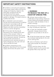
...in a safe place and pass them on accidentally. IMPORTANT SAFETY INSTRUCTIONS READ AND SAVE THESE INSTRUCTIONS Keep these Instructions carefully before installing or using the Ventilation System. ~ This appliance is intended for residential use only. If the service disconnecting means cannot be locked... complies with current safety requirements. To guarantee the electrical safety of the appliance can lead to any doubt, have questions, contact Miele. ~ b) Before servicing or cleaning the appliance, switch power off at the service panel and lock the service disconnecting means to...
...in a safe place and pass them on accidentally. IMPORTANT SAFETY INSTRUCTIONS READ AND SAVE THESE INSTRUCTIONS Keep these Instructions carefully before installing or using the Ventilation System. ~ This appliance is intended for residential use only. If the service disconnecting means cannot be locked... complies with current safety requirements. To guarantee the electrical safety of the appliance can lead to any doubt, have questions, contact Miele. ~ b) Before servicing or cleaning the appliance, switch power off at the service panel and lock the service disconnecting means to...
Operating and Installation manual
Page 4
If in doubt consult a qualified electrician. ~ e) Installation work by unqualified persons could be opened. Repairs and other parts of the cooking area. ~ e) Do not flambé or grill with an open the ...
If in doubt consult a qualified electrician. ~ e) Installation work by unqualified persons could be opened. Repairs and other parts of the cooking area. ~ e) Do not flambé or grill with an open the ...
Operating and Installation manual
Page 6
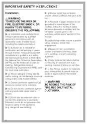
... this ventilation system with any solid-state speed control device. ~ f) Do not use an extension cord to connect the appliance to install the ductwork must be made of approved non-flammable materials. ,WARNING TO REDUCE THE RISK OF FIRE USE ONLY METAL DUCTWORK. 6 IMPORTANT ...or drilling into the wall or ceiling, do not guarantee the required safety of gases through the flue. danger of overheating). ~ g) Do not install this manual. Follow all applicable codes and standards, including fire-rated construction. ~ b) Sufficient air is not given by the manufacturer of the cooktop...
... this ventilation system with any solid-state speed control device. ~ f) Do not use an extension cord to connect the appliance to install the ductwork must be made of approved non-flammable materials. ,WARNING TO REDUCE THE RISK OF FIRE USE ONLY METAL DUCTWORK. 6 IMPORTANT ...or drilling into the wall or ceiling, do not guarantee the required safety of gases through the flue. danger of overheating). ~ g) Do not install this manual. Follow all applicable codes and standards, including fire-rated construction. ~ b) Sufficient air is not given by the manufacturer of the cooktop...

Operating and Installation manual
Page 7
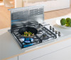
The external blower is designed to the ventilation system by a control cable, and exhaust ductwork and is connected to be installed in a different location than the ventilation system. The external blower is operated via the ventilation system's control panel. 7 The air... is drawn through and cleaned by the grease filters and then directed outside . Functional description The ventilation system offers two installation options: with the internal DAG 500 exhaust blower (not included) with the DAG 1000 external blower (not included) The air is drawn through...
The external blower is designed to the ventilation system by a control cable, and exhaust ductwork and is connected to be installed in a different location than the ventilation system. The external blower is operated via the ventilation system's control panel. 7 The air... is drawn through and cleaned by the grease filters and then directed outside . Functional description The ventilation system offers two installation options: with the internal DAG 500 exhaust blower (not included) with the DAG 1000 external blower (not included) The air is drawn through...
Operating and Installation manual
Page 9
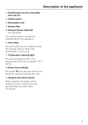
... turn off the fan without retracting the vent. g Temperature warning light The warning light will automatically shut down feature When pressed, the power will be installed so that the exhaust vents to either side, downwards, or to the rear. f Vent collar The vent collar can also be...
... turn off the fan without retracting the vent. g Temperature warning light The warning light will automatically shut down feature When pressed, the power will be installed so that the exhaust vents to either side, downwards, or to the rear. f Vent collar The vent collar can also be...
Operating and Installation manual
Page 17
The installation steps are described in the enclosed "Installation Diagram". Installation Instructions Read these instructions with the appliance for the consumer/user. Please refer to our website to change. Leave these instructions and the "Important Safety Instructions" before installing this ventilation system. Information is subject to obtain the most current product specification, technical & warranty information.
The installation steps are described in the enclosed "Installation Diagram". Installation Instructions Read these instructions with the appliance for the consumer/user. Please refer to our website to change. Leave these instructions and the "Important Safety Instructions" before installing this ventilation system. Information is subject to obtain the most current product specification, technical & warranty information.
Operating and Installation manual
Page 23
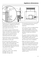
... If an oven or stove is a drawer in the cabinet. The specified dimensions minimum cut -out must be observed. - Note all installation dimensions and guidelines regarding ventilation systems. - If installing the exhaust ducting to the rear (vent duct 10" C (254 mm)). Ensure that any required minimum distance between the front edge of... vent rises is maintained. - Be aware of kitchen cabinets, back splashes and/or racks in the rear of the cooktop is free of the cooktop: DA 6480: 28" (711 mm) DA 6490: 34" (864 mm) -
... If an oven or stove is a drawer in the cabinet. The specified dimensions minimum cut -out must be observed. - Note all installation dimensions and guidelines regarding ventilation systems. - If installing the exhaust ducting to the rear (vent duct 10" C (254 mm)). Ensure that any required minimum distance between the front edge of... vent rises is maintained. - Be aware of kitchen cabinets, back splashes and/or racks in the rear of the cooktop is free of the cooktop: DA 6480: 28" (711 mm) DA 6490: 34" (864 mm) -
Operating and Installation manual
Page 24
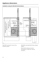
Note that the blower must be accessible to install the venting ductwork. 24 DAG 500 mounted behind the exhaust system. Appliance dimensions Installation using the DAG 500 internal blower DAG 500 mounted in front of the exhaust system.
Note that the blower must be accessible to install the venting ductwork. 24 DAG 500 mounted behind the exhaust system. Appliance dimensions Installation using the DAG 500 internal blower DAG 500 mounted in front of the exhaust system.

Operating and Installation manual
Page 25
Exhaust air ducting to the front. Note that the back must be accessible for the installation of the vent duct. 25 Appliance dimensions Installation using the DAG 1000 external blower connection plate Exhaust air ducting to the rear.
Exhaust air ducting to the front. Note that the back must be accessible for the installation of the vent duct. 25 Appliance dimensions Installation using the DAG 1000 external blower connection plate Exhaust air ducting to the rear.
Operating and Installation manual
Page 26
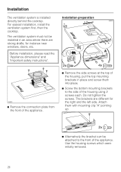
...of the housing, put the top mounting brackets in place and screw them with mounting clip "A" pointing up. ^ Alternatively the bracket can be installed in an area where there are different for instance near windows, doors, etc. The brackets are strong drafts, for the right and the left... bottom mounting brackets to the front of the housing using 2 screws each. Use the housing screws which were initially removed. 26 For easiest installation, install the ventilation system first, then the cooktop. The ventilation system must not be attached to the side of the appliance. Before...
...of the housing, put the top mounting brackets in place and screw them with mounting clip "A" pointing up. ^ Alternatively the bracket can be installed in an area where there are different for instance near windows, doors, etc. The brackets are strong drafts, for the right and the left... bottom mounting brackets to the front of the housing using 2 screws each. Use the housing screws which were initially removed. 26 For easiest installation, install the ventilation system first, then the cooktop. The ventilation system must not be attached to the side of the appliance. Before...

Operating and Installation manual
Page 27
... housing, then push them up under the countertop. ^ Now tighten the brackets on the housing. ^ Carefully pre-drill the mounting holes into the prepared cutout. Installation Alternatively, or additionally, the appliance can also be attached underneath the countertop with 2 screws. ^ Level and align the appliance. ^ Push the bottom mounting bracket on...
... housing, then push them up under the countertop. ^ Now tighten the brackets on the housing. ^ Carefully pre-drill the mounting holes into the prepared cutout. Installation Alternatively, or additionally, the appliance can also be attached underneath the countertop with 2 screws. ^ Level and align the appliance. ^ Push the bottom mounting bracket on...

Operating and Installation manual
Page 28
... appliance at the marked position. ^ Lay the vent housing on the floor on the venting direction. If the ventilation system is installed in the desired direction - Installing the DAG 500 blower box on the front Venting to the side or downwards: ^ Plug the connection cable from the countertop. ...^ Lift the appliance back out of the cabinet. Installation ^ Remove the screws from the ventilation system into the blower motor. ^ Turn the blower box so that the vent collar faces in a cabinet,...
... appliance at the marked position. ^ Lay the vent housing on the floor on the venting direction. If the ventilation system is installed in the desired direction - Installing the DAG 500 blower box on the front Venting to the side or downwards: ^ Plug the connection cable from the countertop. ...^ Lift the appliance back out of the cabinet. Installation ^ Remove the screws from the ventilation system into the blower motor. ^ Turn the blower box so that the vent collar faces in a cabinet,...

Operating and Installation manual
Page 29
Installation ^ Remove the small cover on the rear of the ventilation system. ^ Loosen the two screws holding the blower in the box. ^ Take the blower out of the box. ^ Mount the blower on the front of the ventilation system housing using the 2 screws while positioning the vent collar in the opening of the cover. 29 Venting direction towards the rear: In this case, the DAG 500 blower box must be modified.
Installation ^ Remove the small cover on the rear of the ventilation system. ^ Loosen the two screws holding the blower in the box. ^ Take the blower out of the box. ^ Mount the blower on the front of the ventilation system housing using the 2 screws while positioning the vent collar in the opening of the cover. 29 Venting direction towards the rear: In this case, the DAG 500 blower box must be modified.

Operating and Installation manual
Page 30
Fasten it with 4 screws. ^ Mount the blower box to the housing with the cover you removed from the rear of the blower box. ^ Close the opening in the blower box with 4 screws. 30 Installation ^ Plug the connection cable from the ventilation system into the blower motor. ^ Mount the vent collar on the rear of the ventilation system. ^ Remove the vent collar of the ventilation system housing.
Fasten it with 4 screws. ^ Mount the blower box to the housing with the cover you removed from the rear of the blower box. ^ Close the opening in the blower box with 4 screws. 30 Installation ^ Plug the connection cable from the ventilation system into the blower motor. ^ Mount the vent collar on the rear of the ventilation system. ^ Remove the vent collar of the ventilation system housing.

Operating and Installation manual
Page 31
Installing the DAG 500 blower box on the rear The blower box can also be installed on the back of the ventilation system: Installation ^ When finished, mount the previously removed cover on the front. ^ Remove the large cover on the front. 31 Mounting is the same as if installing on the front. ^ Mount the blower on the rear the same way as described for mounting on the rear.
Installing the DAG 500 blower box on the rear The blower box can also be installed on the back of the ventilation system: Installation ^ When finished, mount the previously removed cover on the front. ^ Remove the large cover on the front. 31 Mounting is the same as if installing on the front. ^ Mount the blower on the rear the same way as described for mounting on the rear.
Operating and Installation manual
Page 32
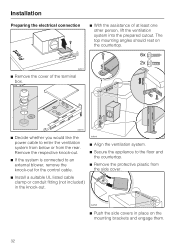
... the respective knock-out. ^ If the system is connected to the floor and the countertop. ^ Remove the protective plastic from the rear. Installation Preparing the electrical connection ^ With the assistance of the terminal box. ^ Decide whether you would like the power cable to enter the ventilation ...the knock-out. ^ Align the ventilation system. ^ Secure the appliance to an external blower, remove the knock-out for the control cable. ^ Install a suitable UL listed cable clamp or conduit fitting (not included) in place on the countertop. ^ Remove the cover of at least one other ...
... the respective knock-out. ^ If the system is connected to the floor and the countertop. ^ Remove the protective plastic from the rear. Installation Preparing the electrical connection ^ With the assistance of the terminal box. ^ Decide whether you would like the power cable to enter the ventilation ...the knock-out. ^ Align the ventilation system. ^ Secure the appliance to an external blower, remove the knock-out for the control cable. ^ Install a suitable UL listed cable clamp or conduit fitting (not included) in place on the countertop. ^ Remove the cover of at least one other ...
Operating and Installation manual
Page 33
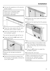
... hold the 0/1 button until it with 2 nuts. ^ Remove the backing from the housing. ^ Connect the appliance to restart the ventilation system. ^ Connect the vent duct. Installation ^ Replace the cover panel and secure it clicks in the bottom of the ventilation system. Observe the "Important safety instructions" and "Electrical connection" warnings.
... hold the 0/1 button until it with 2 nuts. ^ Remove the backing from the housing. ^ Connect the appliance to restart the ventilation system. ^ Connect the vent duct. Installation ^ Replace the cover panel and secure it clicks in the bottom of the ventilation system. Observe the "Important safety instructions" and "Electrical connection" warnings.
Operating and Installation manual
Page 34
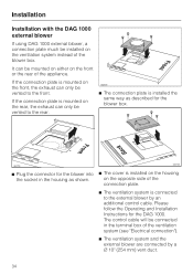
... mm) vent duct. 34 It can be vented to the front. The control cable will be vented to the rear. ^ The connection plate is installed the same way as shown. ^ The cover is mounted on the opposite side of the ventilation system (see "Electrical connection"). ^ The ventilation system... and the external blower are connected by an additional control cable. If the connection plate is installed on the housing on the rear, the exhaust can only be connected in the housing as described for the blower box. ^ Plug the ...
... mm) vent duct. 34 It can be vented to the front. The control cable will be vented to the rear. ^ The connection plate is installed the same way as shown. ^ The cover is mounted on the opposite side of the ventilation system (see "Electrical connection"). ^ The ventilation system... and the external blower are connected by an additional control cable. If the connection plate is installed on the housing on the rear, the exhaust can only be connected in the housing as described for the blower box. ^ Plug the ...
