

Operating manual
Page 1
en - US, CA M.-Nr. 07 781 040 Operating and Installation Instructions Ventilation System DA 249-4 To prevent accidents and appliance damage, read these instructions before installation or use.
en - US, CA M.-Nr. 07 781 040 Operating and Installation Instructions Ventilation System DA 249-4 To prevent accidents and appliance damage, read these instructions before installation or use.
Operating manual
Page 2
... Cleaning and Care 17 Cleaning the casing 17 Grease filter 18 Active charcoal filters 20 Changing the light bulbs 22 After Sales Service 23 Installation instructions 25 Caring for the environment 27 Appliance dimensions 28 Plywood backing 31 Installation 32 Installation 34 Dismantling 34 Air extraction 35 Electrical connection 37 Technical data 38 2
... Cleaning and Care 17 Cleaning the casing 17 Grease filter 18 Active charcoal filters 20 Changing the light bulbs 22 After Sales Service 23 Installation instructions 25 Caring for the environment 27 Appliance dimensions 28 Plywood backing 31 Installation 32 Installation 34 Dismantling 34 Air extraction 35 Electrical connection 37 Technical data 38 2
Operating manual
Page 3
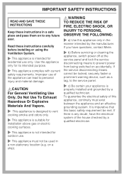
... This appliance is not intended for outdoor use of the appliance can lead to the service panel. ~ c) Be certain your appliance is properly installed and grounded by a qualified technician. Read these instructions in a safe place and pass them on to prevent power from being switched on a ...checked by the manufacturer. on accidentally. If the service disconnecting means cannot be met. If there is any doubt, have questions, contact Miele. ~ b) Before servicing or cleaning the appliance, switch power off at the service panel and lock the service disconnecting means to any ...
... This appliance is not intended for outdoor use of the appliance can lead to the service panel. ~ c) Be certain your appliance is properly installed and grounded by a qualified technician. Read these instructions in a safe place and pass them on to prevent power from being switched on a ...checked by the manufacturer. on accidentally. If the service disconnecting means cannot be met. If there is any doubt, have questions, contact Miele. ~ b) Before servicing or cleaning the appliance, switch power off at the service panel and lock the service disconnecting means to any ...
Operating manual
Page 4
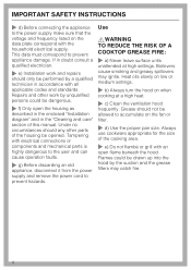
...power supply make sure that the voltage and frequency listed on when cooking at high settings. If in doubt consult a qualified electrician. ~ e) Installation work by unqualified persons could be allowed to accumulate on the fan or filter. ~ d) Use the proper pan size. Use ,WARNING TO ... or medium settings. ~ b) Always turn the hood on the data plate correspond with an open the housing as described in the enclosed "Installation diagram" and in accordance with electrical connections or components and mechanical parts is highly dangerous to the user and can cause operation faults. ~ ...
...power supply make sure that the voltage and frequency listed on when cooking at high settings. If in doubt consult a qualified electrician. ~ e) Installation work by unqualified persons could be allowed to accumulate on the fan or filter. ~ d) Use the proper pan size. Use ,WARNING TO ... or medium settings. ~ b) Always turn the hood on the data plate correspond with an open the housing as described in the enclosed "Installation diagram" and in accordance with electrical connections or components and mechanical parts is highly dangerous to the user and can cause operation faults. ~ ...
Operating manual
Page 6
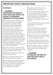
... TO REDUCE THE RISK OF FIRE, ELECTRIC SHOCK, OR INJURY TO PERSONS, OBSERVE THE FOLLOWING: ~ a) Installation work and electrical wiring must be made of the appliance, (e.g. danger of overheating). ~ g) Do not install this hood over cooktops that burn solid fuel. ~ h) Provided a larger distance is not given by qualified person(s) in the "Appliance... through the flue (chimney of this hood with any solid-state speed control device. ~ f) Do not use an extension cord to connect the appliance to install the ductwork must be vented to the outdoors. ~ e) Do not use this manual.
... TO REDUCE THE RISK OF FIRE, ELECTRIC SHOCK, OR INJURY TO PERSONS, OBSERVE THE FOLLOWING: ~ a) Installation work and electrical wiring must be made of the appliance, (e.g. danger of overheating). ~ g) Do not install this hood over cooktops that burn solid fuel. ~ h) Provided a larger distance is not given by qualified person(s) in the "Appliance... through the flue (chimney of this hood with any solid-state speed control device. ~ f) Do not use an extension cord to connect the appliance to install the ductwork must be vented to the outdoors. ~ e) Do not use this manual.

Operating manual
Page 7
... is drawn through a vent at the top of the hood's chimney. Air is turned on, the air pressure of outside . The recirculation mode requires an install kit and charcoal filter which are optional accessories. The hood comes equipped with a non-return flap.
... is drawn through a vent at the top of the hood's chimney. Air is turned on, the air pressure of outside . The recirculation mode requires an install kit and charcoal filter which are optional accessories. The hood comes equipped with a non-return flap.

Operating manual
Page 20
The charcoal filter is installed for use in place. ^ Return the grease filter and decor cover. ^ When the active charcoal filter is designed to access the active charcoal filter. See "... filter for the first time remove the connector for the first time, program the charcoal filter timer. Replacement active charcoal filters can be ordered from Miele. ^ The decor cover must be removed to absorb cooking odors. Reprogramming the charcoal filter timer". 20 Cleaning and Care Active charcoal filters In recirculation mode...
The charcoal filter is installed for use in place. ^ Return the grease filter and decor cover. ^ When the active charcoal filter is designed to access the active charcoal filter. See "... filter for the first time remove the connector for the first time, program the charcoal filter timer. Replacement active charcoal filters can be ordered from Miele. ^ The decor cover must be removed to absorb cooking odors. Reprogramming the charcoal filter timer". 20 Cleaning and Care Active charcoal filters In recirculation mode...
Operating manual
Page 23
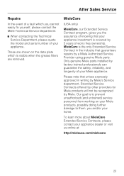
... Miele parts installed by 5 years of worry free ownership. MieleCare is the only Extended Service Contract in writing by Miele's Service department, Extended Service Contracts offered by other providers for Miele products will not be recognized by a Miele Authorized Service Provider using genuine Miele parts...and untrained) service personnel from working on the data plate which you the assurance of knowing that guarantees repairs by Miele. Please note that unless expressly approved in the industry that your appliance investment is covered by factory trained professionals can ...
... Miele parts installed by 5 years of worry free ownership. MieleCare is the only Extended Service Contract in writing by Miele's Service department, Extended Service Contracts offered by other providers for Miele products will not be recognized by a Miele Authorized Service Provider using genuine Miele parts...and untrained) service personnel from working on the data plate which you the assurance of knowing that guarantees repairs by Miele. Please note that unless expressly approved in the industry that your appliance investment is covered by factory trained professionals can ...
Operating manual
Page 25
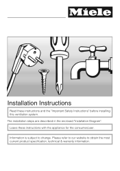
The installation steps are described in the enclosed "Installation Diagram". Information is subject to obtain the most current product specification, technical & warranty information. Installation Instructions Read these instructions with the appliance for the consumer/user. Please refer to our website to change. Leave these instructions and the "Important Safety Instructions" before installing this ventilation system.
The installation steps are described in the enclosed "Installation Diagram". Information is subject to obtain the most current product specification, technical & warranty information. Installation Instructions Read these instructions with the appliance for the consumer/user. Please refer to our website to change. Leave these instructions and the "Important Safety Instructions" before installing this ventilation system.
Operating manual
Page 29
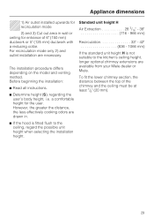
... suitable to the ceiling, regard the possible unit height when selecting the installation height. 29 However, the greater the distance, the less effectively cooking odors are available from your Miele dealer or Miele. To fit the lower chimney section, the distance between the top of... 6" (150 mm) ductwork or 5" (125 mm) ductwork with a reducing collar. Appliance dimensions 1) Air outlet installed upwards for recirculation mode 2) and 3) Cut...
... suitable to the ceiling, regard the possible unit height when selecting the installation height. 29 However, the greater the distance, the less effectively cooking odors are available from your Miele dealer or Miele. To fit the lower chimney section, the distance between the top of... 6" (150 mm) ductwork or 5" (125 mm) ductwork with a reducing collar. Appliance dimensions 1) Air outlet installed upwards for recirculation mode 2) and 3) Cut...
Operating manual
Page 30
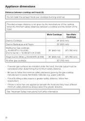
... cooktops < 43,000 BTU (12.6 KW) and no burner > 15,000 BTU (4.5 KW) Single burner (Wok) < 20,500 BTU (6 KW) All other gas cooktops Miele Cooktops Non-Miele Cooktops 24" (610 mm) 26" (660 mm) 26" (660 mm) 30" (760 mm) 26" (660 mm) 30" (760 mm) 30" (760 mm) - If several... gas surfaces are installed under the hood, the total output must be considered when determining the minimum safety distance. - upper cabinets. - Appliance dimensions Distance between a cooktop...
... cooktops < 43,000 BTU (12.6 KW) and no burner > 15,000 BTU (4.5 KW) Single burner (Wok) < 20,500 BTU (6 KW) All other gas cooktops Miele Cooktops Non-Miele Cooktops 24" (610 mm) 26" (660 mm) 26" (660 mm) 30" (760 mm) 26" (660 mm) 30" (760 mm) 30" (760 mm) - If several... gas surfaces are installed under the hood, the total output must be considered when determining the minimum safety distance. - upper cabinets. - Appliance dimensions Distance between a cooktop...
Operating manual
Page 31
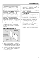
...must be supported by the lower retaining plate. Tape the joints and refinish the wall. ^ Proceed to the enclosed "Installation diagram" to adequately support the weight as outlined on the "Installation diagram". ^ Make a cutting line 3" (76 mm) above and 3" (76 mm) below the outline of the...not damage electrical wiring and other hidden utilities. ^ Remove the drywall between the cutting lines and replace it with plywood of the installed ventilation system will be installed. Plywood backing The majority of the weight of a matching thickness (min. ½" (13 mm) thick). If studs are ...
...must be supported by the lower retaining plate. Tape the joints and refinish the wall. ^ Proceed to the enclosed "Installation diagram" to adequately support the weight as outlined on the "Installation diagram". ^ Make a cutting line 3" (76 mm) above and 3" (76 mm) below the outline of the...not damage electrical wiring and other hidden utilities. ^ Remove the drywall between the cutting lines and replace it with plywood of the installed ventilation system will be installed. Plywood backing The majority of the weight of a matching thickness (min. ½" (13 mm) thick). If studs are ...
Operating manual
Page 33
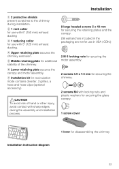
... retaining plate secures the chimney extension. f Lower retaining plate secures the canopy and motor assembly. Installation a 2 protective shields prevent scratches to the chimney during the assembly and installation process. 8 large headed screws 5 x 40 mm for securing the retaining plates and the canopy...and plastic washers for securing the glass canopy. 1 screw cover Installation instruction diagram 1 lever for additional stability of the chimney. e Middle retaining plate for disassembling the chimney 33 g Installation kit for recirculation mode contains diverter, 2 grilles, a hose...
... retaining plate secures the chimney extension. f Lower retaining plate secures the canopy and motor assembly. Installation a 2 protective shields prevent scratches to the chimney during the assembly and installation process. 8 large headed screws 5 x 40 mm for securing the retaining plates and the canopy...and plastic washers for securing the glass canopy. 1 screw cover Installation instruction diagram 1 lever for additional stability of the chimney. e Middle retaining plate for disassembling the chimney 33 g Installation kit for recirculation mode contains diverter, 2 grilles, a hose...
Operating manual
Page 34
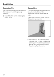
A lever is covered with a protective film to ease the chimney from the chimney, slide the lever between the chimney and the chimney extension and gently apply pressure to prevent scratching during transport. ^ Peel off the film before installing the casing parts. Installation Protective film The casing is enclosed for easier removal of the chimney extension. ^ After removing the screws from its hooks. 34 Dismantling If the hood needs to be disassembled, follow the instructions on the "Installation diagram" in the reverse order.
A lever is covered with a protective film to ease the chimney from the chimney, slide the lever between the chimney and the chimney extension and gently apply pressure to prevent scratching during transport. ^ Peel off the film before installing the casing parts. Installation Protective film The casing is enclosed for easier removal of the chimney extension. ^ After removing the screws from its hooks. 34 Dismantling If the hood needs to be disassembled, follow the instructions on the "Installation diagram" in the reverse order.
Operating manual
Page 35
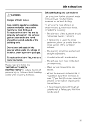
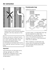
... for exhaust ducting. Air extraction ,WARNING Danger of fire, only use metal ductwork. Follow all connections are secure. - Make sure all local building codes when installing the hood. Do not vent exhaust air into the appliance. - Use ductwork with a wide radius. - The exhaust duct must not be used , the cross section...
... for exhaust ducting. Air extraction ,WARNING Danger of fire, only use metal ductwork. Follow all connections are secure. - Make sure all local building codes when installing the hood. Do not vent exhaust air into the appliance. - Use ductwork with a wide radius. - The exhaust duct must not be used , the cross section...
Operating manual
Page 36
... cases, a condensate trap may also be required to collect and evaporate any condensate which may need to be expelled parallel to reduce condensation. 36 When installing a condensate trap, ensure that it may occur. This optional accessory is positioned vertically and if possible directly above the exhaust outlet. Air extraction Condensate trap...
... cases, a condensate trap may also be required to collect and evaporate any condensate which may need to be expelled parallel to reduce condensation. 36 When installing a condensate trap, ensure that it may occur. This optional accessory is positioned vertically and if possible directly above the exhaust outlet. Air extraction Condensate trap...
Operating manual
Page 37
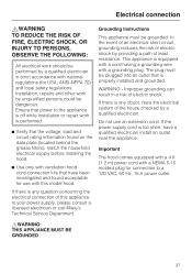
...Do not use with a grounding plug. This appliance is properly installed and grounded. If the power supply cord is performed. ^ Verify... (1.2 m) power cord with national regulations (for use an extension cord. Installation, repairs and other work by providing a path of electric shock. Grounding Instructions...an outlet that power to the appliance is off while installation or repair work is too short, have been investigated and... electrical supply before installing the hood. ^ Use only with ventilation hood cord-connection kits that have a qualified electrician install an outlet near ...
...Do not use with a grounding plug. This appliance is properly installed and grounded. If the power supply cord is performed. ^ Verify... (1.2 m) power cord with national regulations (for use an extension cord. Installation, repairs and other work by providing a path of electric shock. Grounding Instructions...an outlet that power to the appliance is off while installation or repair work is too short, have been investigated and... electrical supply before installing the hood. ^ Use only with ventilation hood cord-connection kits that have a qualified electrician install an outlet near ...
DA249
Page 1
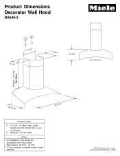
SPECIFICATION SHEETS 010405 Standard 110 Volt Outlet Notes • All installations must be done in accordance with local codes. • Recirculation: 25 5/16" - 34 3/8" • 6" duct connects to blower system inside chimney. 35 7/16" NOTE: Drawing is not to scale. Product Dimensions Decorator Wall Hood DA249-3 E O 11 1/16" 8 1/2" 11 1/4" 12 1/2" Front Perspective 20 9/16" - 30 7/16" See Notes 19 11/16" Location Codes E - 110 Volt - 15 Amp 3-wire power supply connects through top or rear of chimney. O -
SPECIFICATION SHEETS 010405 Standard 110 Volt Outlet Notes • All installations must be done in accordance with local codes. • Recirculation: 25 5/16" - 34 3/8" • 6" duct connects to blower system inside chimney. 35 7/16" NOTE: Drawing is not to scale. Product Dimensions Decorator Wall Hood DA249-3 E O 11 1/16" 8 1/2" 11 1/4" 12 1/2" Front Perspective 20 9/16" - 30 7/16" See Notes 19 11/16" Location Codes E - 110 Volt - 15 Amp 3-wire power supply connects through top or rear of chimney. O -
DA249
Page 2
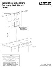
SPECIFICATION SHEETS 010405 Reinforcing material should be affixed to scale. Installation Dimensions Decorator Wall Hoods DA249-3 Structural member Ceiling Line 13 3/8" Area must be reinforced with a minimum of 1/2" plywood. Minimum distance "S" is: - 18" for electric surfaces - 26" for gas surfaces • Area behind mounting plates MUST be reinforced using a minimum of 1/2" plywood backing S + 9 7/8" Notes • Center unit over cooking surface • Distance "S" is not to structural wall members Center Line NOTE: Drawing is determined by the cooking surface.
SPECIFICATION SHEETS 010405 Reinforcing material should be affixed to scale. Installation Dimensions Decorator Wall Hoods DA249-3 Structural member Ceiling Line 13 3/8" Area must be reinforced with a minimum of 1/2" plywood. Minimum distance "S" is: - 18" for electric surfaces - 26" for gas surfaces • Area behind mounting plates MUST be reinforced using a minimum of 1/2" plywood backing S + 9 7/8" Notes • Center unit over cooking surface • Distance "S" is not to structural wall members Center Line NOTE: Drawing is determined by the cooking surface.
