
Operating manual
Page 2
... INSTRUCTIONS 3 Functional description 7 Guide to the Ventilation System 8 Operation 10 Turning on the fan 10 Selecting the power level 10 Delayed Shut Down 12 Turning off the fan 12 Turning the lighting on/off 13 Dimming the lighting 13 Filter timers 14 Checking the filter timers 14 Reprogramming the timers 15 Cleaning and Care 17 Cleaning the casing 17 Grease filter 18 Active charcoal filters 20 Changing the light bulbs 22 After Sales Service 23 Installation instructions 25 Caring...
... INSTRUCTIONS 3 Functional description 7 Guide to the Ventilation System 8 Operation 10 Turning on the fan 10 Selecting the power level 10 Delayed Shut Down 12 Turning off the fan 12 Turning the lighting on/off 13 Dimming the lighting 13 Filter timers 14 Checking the filter timers 14 Reprogramming the timers 15 Cleaning and Care 17 Cleaning the casing 17 Grease filter 18 Active charcoal filters 20 Changing the light bulbs 22 After Sales Service 23 Installation instructions 25 Caring...
Operating manual
Page 3
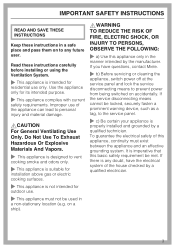
..., contact Miele. ~ b) Before servicing or cleaning the appliance, switch power off at the service panel and lock the service disconnecting means to vent cooking smoke and odors only. ~ This appliance is suitable for installation above gas or electric cooking surfaces. ~ This appliance is not intended for outdoor use. ~ This appliance must exist between the appliance and an effective grounding system. Do Not Use To Exhaust Hazardous Or...
..., contact Miele. ~ b) Before servicing or cleaning the appliance, switch power off at the service panel and lock the service disconnecting means to vent cooking smoke and odors only. ~ This appliance is suitable for installation above gas or electric cooking surfaces. ~ This appliance is not intended for outdoor use. ~ This appliance must exist between the appliance and an effective grounding system. Do Not Use To Exhaust Hazardous Or...
Operating manual
Page 4
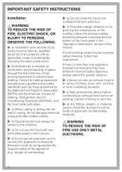
... use cookware appropriate for the size of this manual. Heat oils slowly on low or medium settings. ~ b) Always turn the hood on the data plate correspond with electrical connections or components and mechanical parts is highly dangerous to the user and can cause operation faults. ~ g) Before discarding an old appliance, disconnect it from the power supply and remove the power cord to prevent hazards. IMPORTANT SAFETY INSTRUCTIONS ~ d) Before connecting...
... use cookware appropriate for the size of this manual. Heat oils slowly on low or medium settings. ~ b) Always turn the hood on the data plate correspond with electrical connections or components and mechanical parts is highly dangerous to the user and can cause operation faults. ~ g) Before discarding an old appliance, disconnect it from the power supply and remove the power cord to prevent hazards. IMPORTANT SAFETY INSTRUCTIONS ~ d) Before connecting...

Operating manual
Page 5
... NAFTA ~ Do not allow children to excessive heat from condensation. ~ Never operate gas burners without the grease filters in use. Do not overheat the cookware, e.g. You may be damaged due to play with or operate the appliance or its controls. when using the cooktop to clean the hood. IMPORTANT SAFETY INSTRUCTIONS ,WARNING TO REDUCE THE RISK OF INJURY TO PERSONS IN THE...
... NAFTA ~ Do not allow children to excessive heat from condensation. ~ Never operate gas burners without the grease filters in use. Do not overheat the cookware, e.g. You may be damaged due to play with or operate the appliance or its controls. when using the cooktop to clean the hood. IMPORTANT SAFETY INSTRUCTIONS ,WARNING TO REDUCE THE RISK OF INJURY TO PERSONS IN THE...
Operating manual
Page 6
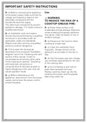
... distance. ~ i) Never connect an exhaust hood to an active chimney, dryer vent, vent flue, or room ventilating ductwork. ~ j) Seek professional advice before connecting an exhaust hood vent to an existing, inactive chimney or vent flue. ~ k) Any fittings, sealant, or materials used to install the ductwork must be vented to the outdoors. ~ e) Do not use an extension cord to connect the appliance to prevent back drafting. Extension cords do not damage electrical wiring and other hidden utilities. ~ d) Ducted hoods must always...
... distance. ~ i) Never connect an exhaust hood to an active chimney, dryer vent, vent flue, or room ventilating ductwork. ~ j) Seek professional advice before connecting an exhaust hood vent to an existing, inactive chimney or vent flue. ~ k) Any fittings, sealant, or materials used to install the ductwork must be vented to the outdoors. ~ e) Do not use an extension cord to connect the appliance to prevent back drafting. Extension cords do not damage electrical wiring and other hidden utilities. ~ d) Ducted hoods must always...

Operating manual
Page 7
... operation: Air extraction Functional description Recirculation mode The air is drawn in and cleaned by the decor panel and the grease filter and directed outside . The filtered air is turned on, the air pressure of the exhaust fan automatically opens the flap blowing the inside air and cooking odors outside . When the hood is then recirculated back into the kitchen through the decor panel, grease filter and an active charcoal filter. The recirculation mode requires an install kit and charcoal filter which are optional accessories. The hood...
... operation: Air extraction Functional description Recirculation mode The air is drawn in and cleaned by the decor panel and the grease filter and directed outside . The filtered air is turned on, the air pressure of the exhaust fan automatically opens the flap blowing the inside air and cooking odors outside . When the hood is then recirculated back into the kitchen through the decor panel, grease filter and an active charcoal filter. The recirculation mode requires an install kit and charcoal filter which are optional accessories. The hood...

Operating manual
Page 9
... used : - The fan can be cleaned. to reset the grease filter timer after cleaning the grease filter (see "Cleaning and Care"). - to show how long the grease filter have been in the recirculation mode. j On/Off button The indicator next to the charcoal filter button lights when the charcoal filters need to be used independently of hours counted by the charcoal filter timer (see "Operation / Reprogramming the timers"). Guide to the Ventilation System a Chimney extension b Recirculation vent For recirculation use with optional accessories c Chimney d Canopy e Overhead lighting...
... used : - The fan can be cleaned. to reset the grease filter timer after cleaning the grease filter (see "Cleaning and Care"). - to show how long the grease filter have been in the recirculation mode. j On/Off button The indicator next to the charcoal filter button lights when the charcoal filters need to be used independently of hours counted by the charcoal filter timer (see "Operation / Reprogramming the timers"). Guide to the Ventilation System a Chimney extension b Recirculation vent For recirculation use with optional accessories c Chimney d Canopy e Overhead lighting...
Operating manual
Page 14
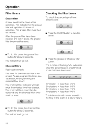
... in memory in place, the grease filter timer must be cleaned. Charcoal filters Recirculation mode The timer for about 3 seconds. Operation Filter timers Grease filter A timer monitors the hours of operation. The indicator for about 3 seconds. After the grease filter have been used : ^ Press the On/Off button to turn the fan on. ^ To do this timer, see "Operation/Reprogramming the charcoal filter timer". The number of flashing "-/+" indicators show the...
... in memory in place, the grease filter timer must be cleaned. Charcoal filters Recirculation mode The timer for about 3 seconds. Operation Filter timers Grease filter A timer monitors the hours of operation. The indicator for about 3 seconds. After the grease filter have been used : ^ Press the On/Off button to turn the fan on. ^ To do this timer, see "Operation/Reprogramming the charcoal filter timer". The number of flashing "-/+" indicators show the...

Operating manual
Page 16
.... Operation Reprogramming the charcoal filter timer The active charcoal filter can not be programmed. ^ Turn off the fan using the On/Off button. The charcoal filter timer is not stored within 4 minutes of the "-/+" indicators will automatically default to select the desired time. ^ Press the Delayed Shut Down and Charcoal Filter buttons at the same time. ^ Store the selection by pressing the charcoal filter button. Before using the hood...
.... Operation Reprogramming the charcoal filter timer The active charcoal filter can not be programmed. ^ Turn off the fan using the On/Off button. The charcoal filter timer is not stored within 4 minutes of the "-/+" indicators will automatically default to select the desired time. ^ Press the Delayed Shut Down and Charcoal Filter buttons at the same time. ^ Store the selection by pressing the charcoal filter button. Before using the hood...

Operating manual
Page 20
Loosen the screw in the connector and remove. ^ Insert the new charcoal filter on the tab at the back of the hood and then firmly press the rear in place. ^ Return the grease filter and decor cover. ^ When the active charcoal filter is designed to absorb cooking odors. Reprogramming the charcoal filter timer". 20 See "Operation - The charcoal filter is installed for use in air extraction mode. See "Cleaning and Care". ^ To remove the active charcoal filter pull down on...
Loosen the screw in the connector and remove. ^ Insert the new charcoal filter on the tab at the back of the hood and then firmly press the rear in place. ^ Return the grease filter and decor cover. ^ When the active charcoal filter is designed to absorb cooking odors. Reprogramming the charcoal filter timer". 20 See "Operation - The charcoal filter is installed for use in air extraction mode. See "Cleaning and Care". ^ To remove the active charcoal filter pull down on...
Operating manual
Page 22
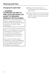
... same type. Please follow the bulb manufacturer's instructions. 22 Cleaning and Care Changing the light bulbs ,WARNING TO REDUCE THE RISK OF FIRE, ELECTRIC SHOCK, OR INJURY TO PERSONS, OBSERVE THE FOLLOWING: Before changing the light bulbs, disconnect the hood from the power supply, see "Important Safety Instructions". ^ Remove the decor cover, see "Cleaning and Care / Removing the decor cover". ^ Pull the old bulb out of its socket and replace it with a new one...
... same type. Please follow the bulb manufacturer's instructions. 22 Cleaning and Care Changing the light bulbs ,WARNING TO REDUCE THE RISK OF FIRE, ELECTRIC SHOCK, OR INJURY TO PERSONS, OBSERVE THE FOLLOWING: Before changing the light bulbs, disconnect the hood from the power supply, see "Important Safety Instructions". ^ Remove the decor cover, see "Cleaning and Care / Removing the decor cover". ^ Pull the old bulb out of its socket and replace it with a new one...
Operating manual
Page 23
... a Miele Authorized Service Provider using genuine Miele parts. After Sales Service Repairs In the event of a fault which is to prevent unauthorized (and untrained) service personnel from working on the data plate which you cannot easily fix yourself, please contact the Miele Technical Service Department. ^ When contacting the Technical Service Department, please quote the model and serial number of your Miele appliance. Only genuine Miele parts installed by Miele. MieleCare is covered...
... a Miele Authorized Service Provider using genuine Miele parts. After Sales Service Repairs In the event of a fault which is to prevent unauthorized (and untrained) service personnel from working on the data plate which you cannot easily fix yourself, please contact the Miele Technical Service Department. ^ When contacting the Technical Service Department, please quote the model and serial number of your Miele appliance. Only genuine Miele parts installed by Miele. MieleCare is covered...
Operating manual
Page 29
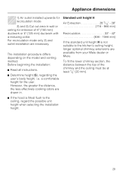
... hood is not suitable to the ceiling, regard the possible unit height when selecting the installation height. 29 Standard unit height H Air Extraction 28 3/16" - 38 716 - 966 mm) Recirculation 33" - 42 836 - 1066 mm) If the standard unit height H is fitted flush to the kitchen's ceiling height, longer optional chimney extensions are available from your Miele dealer or Miele. Before beginning the installation: ^ Read all instructions. ^ Determine height (S), regarding the user's body height...
... hood is not suitable to the ceiling, regard the possible unit height when selecting the installation height. 29 Standard unit height H Air Extraction 28 3/16" - 38 716 - 966 mm) Recirculation 33" - 42 836 - 1066 mm) If the standard unit height H is fitted flush to the kitchen's ceiling height, longer optional chimney extensions are available from your Miele dealer or Miele. Before beginning the installation: ^ Read all instructions. ^ Determine height (S), regarding the user's body height...
Operating manual
Page 31
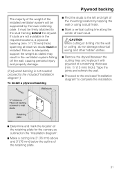
... "Installation diagram".) To install a plywood backing ^ Find the studs to the left and right of the mounting location by the lower retaining plate. It must be supported by tapping the wall or using a stud finder. ^ Mark a vertical cutting line along the center of each stud. ,CAUTION When cutting or drilling into the wall or ceiling, do not damage electrical wiring and other hidden utilities. ^ Remove...
... "Installation diagram".) To install a plywood backing ^ Find the studs to the left and right of the mounting location by the lower retaining plate. It must be supported by tapping the wall or using a stud finder. ^ Mark a vertical cutting line along the center of each stud. ,CAUTION When cutting or drilling into the wall or ceiling, do not damage electrical wiring and other hidden utilities. ^ Remove...
Operating manual
Page 33
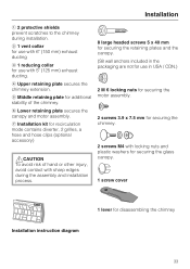
... nuts for securing the motor assembly. 2 screws 3.9 x 7.5 mm for securing the chimney. 2 screws M4 with 5" (125 mm) exhaust ducting. d Upper retaining plate secures the chimney extension. b 1 vent collar for use with 6" (150 mm) exhaust ducting c 1 reducing collar for use in the packaging are not for use with locking nuts and plastic washers for securing the glass canopy. 1 screw cover Installation instruction diagram 1 lever for disassembling the chimney 33 g Installation kit for additional stability of hand...
... nuts for securing the motor assembly. 2 screws 3.9 x 7.5 mm for securing the chimney. 2 screws M4 with 5" (125 mm) exhaust ducting. d Upper retaining plate secures the chimney extension. b 1 vent collar for use with 6" (150 mm) exhaust ducting c 1 reducing collar for use in the packaging are not for use with locking nuts and plastic washers for securing the glass canopy. 1 screw cover Installation instruction diagram 1 lever for disassembling the chimney 33 g Installation kit for additional stability of hand...
Operating manual
Page 34
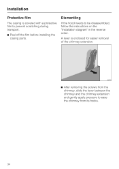
A lever is covered with a protective film to prevent scratching during transport. ^ Peel off the film before installing the casing parts. Installation Protective film The casing is enclosed for easier removal of the chimney extension. ^ After removing the screws from the chimney, slide the lever between the chimney and the chimney extension and gently apply pressure to ease the chimney from its hooks. 34 Dismantling If the hood needs to be disassembled, follow the instructions on the "Installation diagram" in the reverse order.
A lever is covered with a protective film to prevent scratching during transport. ^ Peel off the film before installing the casing parts. Installation Protective film The casing is enclosed for easier removal of the chimney extension. ^ After removing the screws from the chimney, slide the lever between the chimney and the chimney extension and gently apply pressure to ease the chimney from its hooks. 34 Dismantling If the hood needs to be disassembled, follow the instructions on the "Installation diagram" in the reverse order.
Operating manual
Page 35
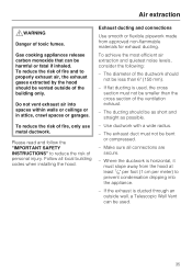
... INSTRUCTIONS" to prevent condensation dripping into spaces within walls or ceilings or in attics, crawl spaces or garages. Do not vent exhaust air into the appliance. - Exhaust ducting and connections Use smooth or flexible pipework made from the hood at least 1/8" per foot (1 cm per meter) to reduce the risk of fire, only use metal ductwork. Make sure all local building codes when installing the hood. Air...
... INSTRUCTIONS" to prevent condensation dripping into spaces within walls or ceilings or in attics, crawl spaces or garages. Do not vent exhaust air into the appliance. - Exhaust ducting and connections Use smooth or flexible pipework made from the hood at least 1/8" per foot (1 cm per meter) to reduce the risk of fire, only use metal ductwork. Make sure all local building codes when installing the hood. Air...
Operating manual
Page 37
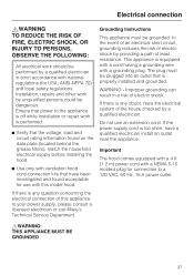
... THE FOLLOWING: All electrical work should be plugged into an outlet that have been investigated and found on the data plate (located behind the grease filters), match the household electrical supply before installing the hood. ^ Use only with ventilation hood cord-connection kits that is properly installed and grounded. The plug must be dangerous. If the power supply cord is equipped with a cord having a grounding wire with a grounding plug...
... THE FOLLOWING: All electrical work should be plugged into an outlet that have been investigated and found on the data plate (located behind the grease filters), match the household electrical supply before installing the hood. ^ Use only with ventilation hood cord-connection kits that is properly installed and grounded. The plug must be dangerous. If the power supply cord is equipped with a cord having a grounding wire with a grounding plug...
DA249
Page 1
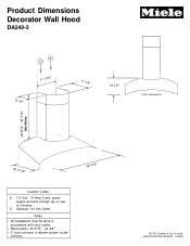
Product Dimensions Decorator Wall Hood DA249-3 E O 11 1/16" 8 1/2" 11 1/4" 12 1/2" Front Perspective 20 9/16" - 30 7/16" See Notes 19 11/16" Location Codes E - 110 Volt - 15 Amp 3-wire power supply connects through top or rear of chimney. O - Standard 110 Volt Outlet Notes • All installations must be done in accordance with local codes. • Recirculation: 25 5/16" - 34 3/8" • 6" duct connects to blower system inside chimney. 35 7/16" NOTE: Drawing is not to scale. SPECIFICATION SHEETS 010405
Product Dimensions Decorator Wall Hood DA249-3 E O 11 1/16" 8 1/2" 11 1/4" 12 1/2" Front Perspective 20 9/16" - 30 7/16" See Notes 19 11/16" Location Codes E - 110 Volt - 15 Amp 3-wire power supply connects through top or rear of chimney. O - Standard 110 Volt Outlet Notes • All installations must be done in accordance with local codes. • Recirculation: 25 5/16" - 34 3/8" • 6" duct connects to blower system inside chimney. 35 7/16" NOTE: Drawing is not to scale. SPECIFICATION SHEETS 010405
DA249
Page 2
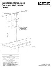
Reinforcing material should be affixed to structural wall members Center Line NOTE: Drawing is determined by the cooking surface. SPECIFICATION SHEETS 010405 Installation Dimensions Decorator Wall Hoods DA249-3 Structural member Ceiling Line 13 3/8" Area must be reinforced with a minimum of 1/2" plywood. Minimum distance "S" is: - 18" for electric surfaces - 26" for gas surfaces • Area behind mounting plates MUST be reinforced using a minimum of 1/2" plywood backing S + 9 7/8" Notes • Center unit over cooking surface • Distance "S" is not to scale.
Reinforcing material should be affixed to structural wall members Center Line NOTE: Drawing is determined by the cooking surface. SPECIFICATION SHEETS 010405 Installation Dimensions Decorator Wall Hoods DA249-3 Structural member Ceiling Line 13 3/8" Area must be reinforced with a minimum of 1/2" plywood. Minimum distance "S" is: - 18" for electric surfaces - 26" for gas surfaces • Area behind mounting plates MUST be reinforced using a minimum of 1/2" plywood backing S + 9 7/8" Notes • Center unit over cooking surface • Distance "S" is not to scale.


