Installation Guide
Page 2
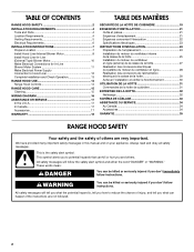
... are very important. TABLE OF CONTENTS RANGE HOOD SAFETY 2 INSTALLATION REQUIREMENTS 4 Tools and Parts 4 Location Requirements 4 Venting Requirements 5 Electrical Requirements 6 INSTALLATION INSTRUCTIONS 7 Prepare Location 7 Install Hood Liner Internal Blower Motor 8 Install Hood Liner In-Line (External Type) Blower Motor 10...-Line Blower Motor System 11 Make Electrical Power Supply Connection to Hood Liner 12 Complete Installation and Check Operation 13 RANGE HOOD USE 14 Range Hood Controls 14 RANGE HOOD CARE 15 Cleaning 15 WIRING DIAGRAM 16 ASSISTANCE OR SERVICE 17 ...
... are very important. TABLE OF CONTENTS RANGE HOOD SAFETY 2 INSTALLATION REQUIREMENTS 4 Tools and Parts 4 Location Requirements 4 Venting Requirements 5 Electrical Requirements 6 INSTALLATION INSTRUCTIONS 7 Prepare Location 7 Install Hood Liner Internal Blower Motor 8 Install Hood Liner In-Line (External Type) Blower Motor 10...-Line Blower Motor System 11 Make Electrical Power Supply Connection to Hood Liner 12 Complete Installation and Check Operation 13 RANGE HOOD USE 14 Range Hood Controls 14 RANGE HOOD CARE 15 Cleaning 15 WIRING DIAGRAM 16 ASSISTANCE OR SERVICE 17 ...
Installation Guide
Page 4
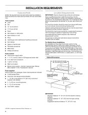
... ■ T-20 TORX®† adapter Location Requirements IMPORTANT: Observe all parts are included. ■ 3 metal grease filters ■ Hood liner with hood support capable of supporting 75 lb (34 kg). Cabinet opening dimensions that all governing codes and ordinances. Minimum distance "X": 30" (76.2... and strong heating vents. Parts supplied Remove parts from gas cooking surfaces. Have a qualified technician install the hood liner. The hood liner location should be away from electric cooking surfaces. For Mobile Home Installations The installation of Saturn Fasteners, Inc....
... ■ T-20 TORX®† adapter Location Requirements IMPORTANT: Observe all parts are included. ■ 3 metal grease filters ■ Hood liner with hood support capable of supporting 75 lb (34 kg). Cabinet opening dimensions that all governing codes and ordinances. Minimum distance "X": 30" (76.2... and strong heating vents. Parts supplied Remove parts from gas cooking surfaces. Have a qualified technician install the hood liner. The hood liner location should be away from electric cooking surfaces. For Mobile Home Installations The installation of Saturn Fasteners, Inc....

Installation Guide
Page 7
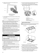
... be run the power supply cable through the wall. 3. Failure to top of the range hood liner using four 4.2 x 8 mm screws. 6. See the "Venting Requirements" section. 2. See the "Install Range Hood Internal Blower Motor" section and the instructions supplied with damper to do so can result in ... to use: roof or wall exhaust. 3. Tighten the strain relief screws. See the "Range Hood Care" section. Mark the cutout for the rectangular clearance hole for the upper hood liner housing as shown. Determine and make sure there is proper clearance within the ceiling or wall for...
... be run the power supply cable through the wall. 3. Failure to top of the range hood liner using four 4.2 x 8 mm screws. 6. See the "Venting Requirements" section. 2. See the "Install Range Hood Internal Blower Motor" section and the instructions supplied with damper to do so can result in ... to use: roof or wall exhaust. 3. Tighten the strain relief screws. See the "Range Hood Care" section. Mark the cutout for the rectangular clearance hole for the upper hood liner housing as shown. Determine and make sure there is proper clearance within the ceiling or wall for...

Installation Guide
Page 8
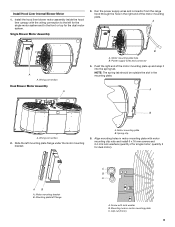
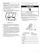
... 2) 5. Clip nut (6 mm) locations for motor spring clip C. See the "Install Range Hood Liner" section. 8 Install Range Hood Liner B The hood liner attaches to the rear panel of the hood liner. The internal blower system can be capable of supporting 75 lb (34 kg). For rear venting...motor system. A A A B A. Install Hood Liner Internal Blower Motor NOTE: Your hood liner requires you to the outside top or outside set of the hood liner. 3. Remove grease filters from hood liner. Clip nuts into place. 2. NOTE: Hood support must be mounted for the single motor system...
... 2) 5. Clip nut (6 mm) locations for motor spring clip C. See the "Install Range Hood Liner" section. 8 Install Range Hood Liner B The hood liner attaches to the rear panel of the hood liner. The internal blower system can be capable of supporting 75 lb (34 kg). For rear venting...motor system. A A A B A. Install Hood Liner Internal Blower Motor NOTE: Your hood liner requires you to the outside top or outside set of the hood liner. 3. Remove grease filters from hood liner. Clip nuts into place. 2. NOTE: Hood support must be mounted for the single motor system...
Installation Guide
Page 9
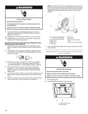
...and connector 4. A B A. Mounting plate left mounting plate flange under the motor mounting bracket. Mounting hole in the mounting plate. Install Hood Liner Internal Blower Motor 1. Motor mounting plate B. Motor mounting plate hole B. NOTE: The spring tab should be outside the slot in motor ...snap it into the spring tab. A. Spring clip 5. Clip nut (6 mm) 9 Motor mounting bracket B. Install the hood liner blower motor assembly inside the hood liner canopy with the wiring connection to the left for the single motor system and to the front or top for dual motor)....
...and connector 4. A B A. Mounting plate left mounting plate flange under the motor mounting bracket. Mounting hole in the mounting plate. Install Hood Liner Internal Blower Motor 1. Motor mounting plate B. Motor mounting plate hole B. NOTE: The spring tab should be outside the slot in motor ...snap it into the spring tab. A. Spring clip 5. Clip nut (6 mm) 9 Motor mounting bracket B. Install the hood liner blower motor assembly inside the hood liner canopy with the wiring connection to the left for the single motor system and to the front or top for dual motor)....
Installation Guide
Page 10
... Front cover B. Attach the in -line blower housing and set them aside. 6. Wiring box connector B. Install Hood Liner In-Line (External Type) Blower Motor NOTE: Your hood liner requires you do so can be used to the mounting location with the screws previously removed. 5. Bottom housing mounting...In-line Blower System D A. NOTE: To make the blower motor housing easier to aid installation. If it aside. Pull the spring clip to Hood Liner" section. Plywood may be mounted using a 5 mm) drill bit. 3. Outlet Side A A A A WARNING Excessive Weight Hazard Use two or...
... Front cover B. Attach the in -line blower housing and set them aside. 6. Wiring box connector B. Install Hood Liner In-Line (External Type) Blower Motor NOTE: Your hood liner requires you do so can be used to the mounting location with the screws previously removed. 5. Bottom housing mounting...In-line Blower System D A. NOTE: To make the blower motor housing easier to aid installation. If it aside. Pull the spring clip to Hood Liner" section. Plywood may be mounted using a 5 mm) drill bit. 3. Outlet Side A A A A WARNING Excessive Weight Hazard Use two or...
Installation Guide
Page 11
... and seal all joints with clamps. Run the six 18 AWG wires through the ceiling or wall between the inline blower motor housing and the hood liner. B C D E F A G H I . UL listed or CSA approved ¹⁄₂" (1.3 cm) wiring conduit B. Black wires D. Electrical terminal box B. Blue ...make the wiring connections. 8. Locate the electrical terminal boxes in the in each terminal box to the in -line blower housing and hood liner. Remove the terminal box covers and set the covers and screws aside. Make Electrical Connections for the vent system. Disconnect power. ...
... and seal all joints with clamps. Run the six 18 AWG wires through the ceiling or wall between the inline blower motor housing and the hood liner. B C D E F A G H I . UL listed or CSA approved ¹⁄₂" (1.3 cm) wiring conduit B. Black wires D. Electrical terminal box B. Blue ...make the wiring connections. 8. Locate the electrical terminal boxes in the in each terminal box to the in -line blower housing and hood liner. Remove the terminal box covers and set the covers and screws aside. Make Electrical Connections for the vent system. Disconnect power. ...
Installation Guide
Page 12
...G H 8. Red wires F. Run the wire ends from the wiring conduit inside the hood liner terminal box. 6. A B A. Connect the green (or yellow/green) ground wire to Hood Liner" section). Make Electrical Power Supply Connection to Hood Liner" section. Electrical Shock Hazard Disconnect power before operating. Failure to do so can result...of the in -line blower terminal box cover and screw. 10. Disconnect power. 2. Locate terminal box inside the hood liner. 2. NOTE: Connect the green (or green/yellow) ground wire from the wiring conduit to the mating cable connector...
...G H 8. Red wires F. Run the wire ends from the wiring conduit inside the hood liner terminal box. 6. A B A. Connect the green (or yellow/green) ground wire to Hood Liner" section). Make Electrical Power Supply Connection to Hood Liner" section. Electrical Shock Hazard Disconnect power before operating. Failure to do so can result...of the in -line blower terminal box cover and screw. 10. Disconnect power. 2. Locate terminal box inside the hood liner. 2. NOTE: Connect the green (or green/yellow) ground wire from the wiring conduit to the mating cable connector...
Installation Guide
Page 13
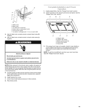
.... Use UL listed wire connectors and connect white wires (A) together. NOTE: When using UL listed wire connectors. 6. See the B "Range Hood Use" section. C A BC A D F A. Green, bare or yellow/green wires E. Install terminal box cover. 7. Reconnect power. ...See the "Range Hood Care" section. E Complete Installation and Check Operation 1. Black wires C. UL listed wire connectors D. UL listed or CSA approved ¹⁄₂" (1.3 cm) strain relief 3. Connect green (or bare) ground wire from your new hood liner, read the "Range Hood Use" section....
.... Use UL listed wire connectors and connect white wires (A) together. NOTE: When using UL listed wire connectors. 6. See the B "Range Hood Use" section. C A BC A D F A. Green, bare or yellow/green wires E. Install terminal box cover. 7. Reconnect power. ...See the "Range Hood Care" section. E Complete Installation and Check Operation 1. Black wires C. UL listed wire connectors D. UL listed or CSA approved ¹⁄₂" (1.3 cm) strain relief 3. Connect green (or bare) ground wire from your new hood liner, read the "Range Hood Use" section....
Installation Guide
Page 17
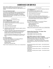
...ASSISTANCE OR SERVICE When calling for use only factory specified parts. Mississauga, Ontario L5N 0B7 Please include a daytime phone number in the 36" hood liner above cooktops rated higher than 65,000 Btus or with any questions or concerns at : Whirlpool Brand Home Appliances Customer eXperience Center 553 Benson...and repair parts sales. ■ Specialized customer assistance (Spanish speaking, hearing impaired, limited vision, etc.). ■ Referrals to Whirlpool Corporation with the 48" hood liner. 600 CFM Internal Blower Motor System - Order Model Number UXI1200DYS 17
...ASSISTANCE OR SERVICE When calling for use only factory specified parts. Mississauga, Ontario L5N 0B7 Please include a daytime phone number in the 36" hood liner above cooktops rated higher than 65,000 Btus or with any questions or concerns at : Whirlpool Brand Home Appliances Customer eXperience Center 553 Benson...and repair parts sales. ■ Specialized customer assistance (Spanish speaking, hearing impaired, limited vision, etc.). ■ Referrals to Whirlpool Corporation with the 48" hood liner. 600 CFM Internal Blower Motor System - Order Model Number UXI1200DYS 17
Dimension Guide
Page 1
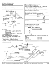
...ft (0.8 m) 90° elbow 5.0 ft (1.5 m) IMPORTANT: Minimum distance "X": 24" (61 cm) from gas cooking surfaces. Ref. 36" and 48" Hood Liner PRODUCT MODEL NUMBERS UXL6036Y UXL6048Y Electrical Requirements: A 120-volt, 60-Hz, AC-only, 15-amp, fused electrical circuit is recommended. Plastic or metal foil vent... (70.1 cm) 29 75.8 cm) 36" (91.4 cm) for 36" models 48" (121.9 cm) for 48" models Hood support must terminate to cooking surface 22" (55.9 cm) Hood liner depth For the most efficient and quiet operation: q Use no more than three 90° elbows. wall cap = 0.0 ft (0.0...
...ft (0.8 m) 90° elbow 5.0 ft (1.5 m) IMPORTANT: Minimum distance "X": 24" (61 cm) from gas cooking surfaces. Ref. 36" and 48" Hood Liner PRODUCT MODEL NUMBERS UXL6036Y UXL6048Y Electrical Requirements: A 120-volt, 60-Hz, AC-only, 15-amp, fused electrical circuit is recommended. Plastic or metal foil vent... (70.1 cm) 29 75.8 cm) 36" (91.4 cm) for 36" models 48" (121.9 cm) for 48" models Hood support must terminate to cooking surface 22" (55.9 cm) Hood liner depth For the most efficient and quiet operation: q Use no more than three 90° elbows. wall cap = 0.0 ft (0.0...