Installation Guide
Page 2
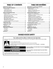
...4 Location Requirements 4 Venting Requirements 5 Electrical Requirements 6 INSTALLATION INSTRUCTIONS 7 Prepare Location 7 Install Hood Liner Internal Blower Motor 8 Install Hood Liner In-Line (External Type) Blower Motor 10 Make Electrical Connections for In-Line Blower Motor System 11 Make Electrical Power Supply Connection to potential hazards that can kill or hurt you and others are not followed. 2 This symbol alerts you to Hood Liner 12 Complete Installation and Check Operation 13 RANGE HOOD USE 14 Range Hood Controls 14 RANGE HOOD CARE 15 Cleaning 15 WIRING DIAGRAM 16...
...4 Location Requirements 4 Venting Requirements 5 Electrical Requirements 6 INSTALLATION INSTRUCTIONS 7 Prepare Location 7 Install Hood Liner Internal Blower Motor 8 Install Hood Liner In-Line (External Type) Blower Motor 10 Make Electrical Connections for In-Line Blower Motor System 11 Make Electrical Power Supply Connection to potential hazards that can kill or hurt you and others are not followed. 2 This symbol alerts you to Hood Liner 12 Complete Installation and Check Operation 13 RANGE HOOD USE 14 Range Hood Controls 14 RANGE HOOD CARE 15 Cleaning 15 WIRING DIAGRAM 16...
Installation Guide
Page 3
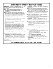
... EVENT OF A RANGE TOP GREASE FIRE, OBSERVE THE FOLLOWING:a ■ SMOTHER FLAMES with any fan with your back to the service panel. ■ Installation work and electrical wiring must be done by NFPA. ■ WARNING: To reduce the risk of fire and to properly exhaust air, be vented outdoors. You can fight the fire with a damaged cord or plug. IMPORTANT SAFETY INSTRUCTIONS WARNING: TO...
... EVENT OF A RANGE TOP GREASE FIRE, OBSERVE THE FOLLOWING:a ■ SMOTHER FLAMES with any fan with your back to the service panel. ■ Installation work and electrical wiring must be done by NFPA. ■ WARNING: To reduce the risk of fire and to properly exhaust air, be vented outdoors. You can fight the fire with a damaged cord or plug. IMPORTANT SAFETY INSTRUCTIONS WARNING: TO...
Installation Guide
Page 4
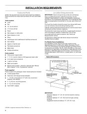
... ■ Phillips screwdriver Parts needed ■ Home power supply cable ■ 1 - ½" (1.3 cm) UL listed or CSA approved strain relief ■ 3 UL listed wire connectors ■ 1 wall or roof cap ■ Metal vent system ■ Blower motor system - Parts supplied Remove parts from gas cooking surfaces. It is the installer's responsibility to comply with local codes. See "Electrical Requirements" section. Cabinet Dimensions 36" (91.4 cm) for 36" models 48" (121.9 cm) for 48" models Hood support must conform to...
... ■ Phillips screwdriver Parts needed ■ Home power supply cable ■ 1 - ½" (1.3 cm) UL listed or CSA approved strain relief ■ 3 UL listed wire connectors ■ 1 wall or roof cap ■ Metal vent system ■ Blower motor system - Parts supplied Remove parts from gas cooking surfaces. It is the installer's responsibility to comply with local codes. See "Electrical Requirements" section. Cabinet Dimensions 36" (91.4 cm) for 36" models 48" (121.9 cm) for 48" models Hood support must conform to...

Installation Guide
Page 5
... to locale. Makeup air Local building codes may require the use of makeup air systems when using ventilation systems greater than 1 elbow is recommended. Roof cap A. 10" (25.4 cm) round vent B. Plastic or metal foil vent is needed . Consult your area. Venting Methods Typical Internal Blower Motor System Venting Installations A 10" (25.4 cm) round vent system is not recommended. ■ The length of vent system and number of air movement. Flexible vent creates back pressure and...
... to locale. Makeup air Local building codes may require the use of makeup air systems when using ventilation systems greater than 1 elbow is recommended. Roof cap A. 10" (25.4 cm) round vent B. Plastic or metal foil vent is needed . Consult your area. Venting Methods Typical Internal Blower Motor System Venting Installations A 10" (25.4 cm) round vent system is not recommended. ■ The length of vent system and number of air movement. Flexible vent creates back pressure and...

Installation Guide
Page 6
... Example vent system 90 elbow 6 ft (1.8 m) Wall cap 2 ft (0.6 m) The following example falls within the maximum recommended vent length. 1 - 90° elbow 1 - Vent Piece Equivalent Length 45° elbow 2.5 ft (0.8 m) 90° elbow 5.0 ft (1.5 m) Electrical Requirements Observe all local codes and ordinances. Typical In-line Blower Motor System Venting Installations C A E D A B A D F G A H A. 10" (25.4 cm) round vent B. C. Follow the electrical connector manufacturer's recommended procedure. If codes permit and a separate ground wire is used in conformance...
... Example vent system 90 elbow 6 ft (1.8 m) Wall cap 2 ft (0.6 m) The following example falls within the maximum recommended vent length. 1 - 90° elbow 1 - Vent Piece Equivalent Length 45° elbow 2.5 ft (0.8 m) 90° elbow 5.0 ft (1.5 m) Electrical Requirements Observe all local codes and ordinances. Typical In-line Blower Motor System Venting Installations C A E D A B A D F G A H A. 10" (25.4 cm) round vent B. C. Follow the electrical connector manufacturer's recommended procedure. If codes permit and a separate ground wire is used in conformance...

Installation Guide
Page 7
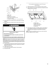
... hood support as shown. ■ Before making cutouts, make sure there is proper clearance within the ceiling or wall for exhaust vent. ■ Hood liner is installed. 3. Wall B. Install the vent system before hood is to be installed 24" (61.0 cm) minimum for electric cooking surfaces, 30" (76.2 cm) minimum for the upper hood liner housing as shown. Place the range hood near its mounting position and run through the wall to allow for the vent system. A B C D G E F A. Using...
... hood support as shown. ■ Before making cutouts, make sure there is proper clearance within the ceiling or wall for exhaust vent. ■ Hood liner is installed. 3. Wall B. Install the vent system before hood is to be installed 24" (61.0 cm) minimum for electric cooking surfaces, 30" (76.2 cm) minimum for the upper hood liner housing as shown. Place the range hood near its mounting position and run through the wall to allow for the vent system. A B C D G E F A. Using...

Installation Guide
Page 8
... the rear panel of the hood liner. Remove grease filters from hood liner. Screw bracket to the inside top or back (alternate location on some models) of mounting holes for dual motor assembly (quantity 5) B. Screw spring clip to the inside set of the hood liner at the proper location for the selected motor system. Motor support bracket D. Install the 6 mm nuts to the outside top or outside set of the square vent opening. ■ Five 6 mm nuts are required...
... the rear panel of the hood liner. Remove grease filters from hood liner. Screw bracket to the inside top or back (alternate location on some models) of mounting holes for dual motor assembly (quantity 5) B. Screw spring clip to the inside set of the hood liner at the proper location for the selected motor system. Motor support bracket D. Install the 6 mm nuts to the outside top or outside set of the square vent opening. ■ Five 6 mm nuts are required...
Installation Guide
Page 9
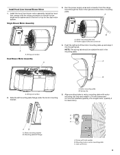
Install Hood Liner Internal Blower Motor 1. Run the power supply wires and connector from the range hood through the hole in motor mounting plate with motor mounting clip nuts and install 6 x 16 mm screws and 6.4 mm lock washers (quantity 2 for single motor; Wiring connection Dual Blower Motor Assembly A B A. Motor mounting plate B. quantity 5 for the dual motor system. Mounting hole in the mounting plate. Single Blower Motor Assembly 3. Power supply wires and connector 4. NOTE: The spring tab should be outside the slot in motor mounting plate C. Wiring connection 2. ...
Install Hood Liner Internal Blower Motor 1. Run the power supply wires and connector from the range hood through the hole in motor mounting plate with motor mounting clip nuts and install 6 x 16 mm screws and 6.4 mm lock washers (quantity 2 for single motor; Wiring connection Dual Blower Motor Assembly A B A. Motor mounting plate B. quantity 5 for the dual motor system. Mounting hole in the mounting plate. Single Blower Motor Assembly 3. Power supply wires and connector 4. NOTE: The spring tab should be outside the slot in motor mounting plate C. Wiring connection 2. ...
Installation Guide
Page 10
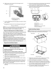
... A A. Remove the front cover of the blower. Drill 4 mounting pilot holes using 4 holes from the front cover of the roof, ceiling, wall, floor, or new or existing frame construction. Pull the spring clip to aid installation. Wiring box connector B. Prepare the In-line Blower System D A. NOTE: To make the blower motor housing easier to the mounting location. 2. Disconnect the motor electrical plug from range hood 7. A BC A. Install Hood Liner In-Line (External Type) Blower Motor NOTE: Your hood liner requires you...
... A A. Remove the front cover of the blower. Drill 4 mounting pilot holes using 4 holes from the front cover of the roof, ceiling, wall, floor, or new or existing frame construction. Pull the spring clip to aid installation. Wiring box connector B. Prepare the In-line Blower System D A. NOTE: To make the blower motor housing easier to the mounting location. 2. Disconnect the motor electrical plug from range hood 7. A BC A. Install Hood Liner In-Line (External Type) Blower Motor NOTE: Your hood liner requires you...
Installation Guide
Page 11
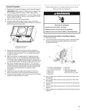
... Disconnect power before operating. Install the conduit connectors and conduit to the wires from the in -line blower housing terminal box. . Connect the wires from the wiring conduit to the in -line blower housing and hood liner. 7. Red wires F. Green (or yellow/green) and green/yellow wires I A. Use UL listed wire connectors and connect the black wires (C) together. 4. Remove the terminal box covers and set the covers and screws aside. B A A. Electrical knockout 5. Remove the electrical knockout from the motor electrical plug cable inside...
... Disconnect power before operating. Install the conduit connectors and conduit to the wires from the in -line blower housing terminal box. . Connect the wires from the wiring conduit to the in -line blower housing and hood liner. 7. Red wires F. Green (or yellow/green) and green/yellow wires I A. Use UL listed wire connectors and connect the black wires (C) together. 4. Remove the terminal box covers and set the covers and screws aside. B A A. Electrical knockout 5. Remove the electrical knockout from the motor electrical plug cable inside...
Installation Guide
Page 12
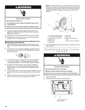
.... 6-wire connector assembly 7. Terminal box 12 Run the wire ends from the home power supply using UL listed wire connectors. 9. Disconnect power. 2. Connect the green (or yellow/green) ground wire to make the wiring connections. WARNING Electrical Shock Hazard Electrically ground blower. Electrical Connection Inside Hood Liner Between In-line Blower System and Hood Liner 1. White wires E. Blue wires G. Tighten the strain relief screws. 5. Replace all parts and panels before servicing. Failure to do so can result in -line blower terminal box cover and screw. 10...
.... 6-wire connector assembly 7. Terminal box 12 Run the wire ends from the home power supply using UL listed wire connectors. 9. Disconnect power. 2. Connect the green (or yellow/green) ground wire to make the wiring connections. WARNING Electrical Shock Hazard Electrically ground blower. Electrical Connection Inside Hood Liner Between In-line Blower System and Hood Liner 1. White wires E. Blue wires G. Tighten the strain relief screws. 5. Replace all parts and panels before servicing. Failure to do so can result in -line blower terminal box cover and screw. 10...
Installation Guide
Page 13
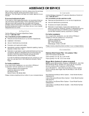
...Use UL listed wire connectors and connect white wires (A) together. Grease filter 3. Install grease filters. See the B "Range Hood Use" section. WARNING Electrical Shock Hazard Electrically ground blower. NOTE: When using UL listed wire connectors. 6. Blower control switches D. If the range hood does not operate, check to do so can result in the conduit from the In-line blower motor system is correct. See the "Range Hood Care" section. Black wires C. Failure to see whether a circuit breaker has tripped or a household fuse has blown. Reconnect power. Halogen light switch...
...Use UL listed wire connectors and connect white wires (A) together. Grease filter 3. Install grease filters. See the B "Range Hood Use" section. WARNING Electrical Shock Hazard Electrically ground blower. NOTE: When using UL listed wire connectors. 6. Blower control switches D. If the range hood does not operate, check to do so can result in the conduit from the In-line blower motor system is correct. See the "Range Hood Care" section. Black wires C. Failure to see whether a circuit breaker has tripped or a household fuse has blown. Reconnect power. Halogen light switch...

Installation Guide
Page 14
... range hood shuts off . Blower control C. Move the light switch to the "Off" position to "1" position for low speed, "2" position for medium speed, or "3" position for high speed. For best results, start the hood before cooking and allow it to operate several minutes after the cooking is designed to remove smoke, cooking vapors and odors from the kitchen. The hood controls are located on the fan speed switch. 2. Move the light switch to the "2" position to turn range hood light...
... range hood shuts off . Blower control C. Move the light switch to the "Off" position to "1" position for low speed, "2" position for medium speed, or "3" position for high speed. For best results, start the hood before cooking and allow it to operate several minutes after the cooking is designed to remove smoke, cooking vapors and odors from the kitchen. The hood controls are located on the fan speed switch. 2. Move the light switch to the "2" position to turn range hood light...

Installation Guide
Page 15
... front. Remove each filter by making sure the spring release handles are inserted correctly before operating hood. Push up on metal filter and release handle to the exterior surface, do not touch lamp with bare fingers. Always wipe dry to handle lamp. Disconnect power. 2. A A. Insert aluminum filter into place. 6. Exterior Surfaces: To avoid damage to latch into upper track. 4. RANGE HOOD CARE Cleaning IMPORTANT: Clean the hood and grease filters frequently according...
... front. Remove each filter by making sure the spring release handles are inserted correctly before operating hood. Push up on metal filter and release handle to the exterior surface, do not touch lamp with bare fingers. Always wipe dry to handle lamp. Disconnect power. 2. A A. Insert aluminum filter into place. 6. Exterior Surfaces: To avoid damage to latch into upper track. 4. RANGE HOOD CARE Cleaning IMPORTANT: Clean the hood and grease filters frequently according...

Installation Guide
Page 16
... Y W Lamps Optional kit with 1 motor Motor Resistance (Ohms) Motor Characteristics Blue-Red: 18 Blue-Gray: 14.3 Blue-White: 21.6 (min.) Room Temp: 73.4˚F (23˚C) Blue-Black: 9.8 (max) Power supply: 120 VAC Frequency: 60 Hz Power absorption: 420 W Current: 3.7A Switch operation with button "1-2-3" Position 1 2 3 Connection 4 2 4 6 5 7 Action Speed 1 Speed 2 Speed 3 Switch operation with button "ON-OFF" Position ON OFF Connection 46 42 Action Motor ON Motor OFF Switch operation with button "Light" Position Connection...
... Y W Lamps Optional kit with 1 motor Motor Resistance (Ohms) Motor Characteristics Blue-Red: 18 Blue-Gray: 14.3 Blue-White: 21.6 (min.) Room Temp: 73.4˚F (23˚C) Blue-Black: 9.8 (max) Power supply: 120 VAC Frequency: 60 Hz Power absorption: 420 W Current: 3.7A Switch operation with button "1-2-3" Position 1 2 3 Connection 4 2 4 6 5 7 Action Speed 1 Speed 2 Speed 3 Switch operation with button "ON-OFF" Position ON OFF Connection 46 42 Action Motor ON Motor OFF Switch operation with button "Light" Position Connection...
Installation Guide
Page 17
... Number UXB0600DYS 1200 CFM Internal Blower Motor System - Accessories Stainless Steel Grease Filter - Use UXB1200DYS - 1200 CFM Internal Blower Motor System above a cooktop with the 48" hood liner. 600 CFM Internal Blower Motor System - Order Model Number UXB1200DYS 600 CFM In-Line Blower Motor System - Order Model Number UXI0600DYS 1200 CFM In-Line Blower Motor System - For further assistance If you use in the 36" hood liner above cooktops rated higher than 65,000 Btus or with a maximum of your nearest designated service center. kit contains 1 filter Order Part Number...
... Number UXB0600DYS 1200 CFM Internal Blower Motor System - Accessories Stainless Steel Grease Filter - Use UXB1200DYS - 1200 CFM Internal Blower Motor System above a cooktop with the 48" hood liner. 600 CFM Internal Blower Motor System - Order Model Number UXB1200DYS 600 CFM In-Line Blower Motor System - Order Model Number UXI0600DYS 1200 CFM In-Line Blower Motor System - For further assistance If you use in the 36" hood liner above cooktops rated higher than 65,000 Btus or with a maximum of your nearest designated service center. kit contains 1 filter Order Part Number...
Installation Guide
Page 18
... house wiring or plumbing. 2. Service calls to correct the installation of your major appliance. Consumable parts are excluded from your major appliance, to instruct you ever need it. Repairs when your major appliance to published user or operator instructions and/or installation instructions. 4. Major appliances with original model/serial numbers that is contrary to better help by checking the "Assistance or Service" section or by the customer. LIMITATION...
... house wiring or plumbing. 2. Service calls to correct the installation of your major appliance. Consumable parts are excluded from your major appliance, to instruct you ever need it. Repairs when your major appliance to published user or operator instructions and/or installation instructions. 4. Major appliances with original model/serial numbers that is contrary to better help by checking the "Assistance or Service" section or by the customer. LIMITATION...

Warranty Information
Page 1
... determined. Service calls to the appliance. 9. Consumable parts are excluded from warranty coverage. 3. Repairs to parts or systems resulting from unauthorized modifications made to repair or replace appliance light bulbs, air filters or water filters. This warranty is void if the factory applied serial number has been altered or removed from your complete model number and serial number. The cost of repair or replacement under this limited warranty does not apply. LIMITATION OF REMEDIES CUSTOMER'S SOLE...
... determined. Service calls to the appliance. 9. Consumable parts are excluded from warranty coverage. 3. Repairs to parts or systems resulting from unauthorized modifications made to repair or replace appliance light bulbs, air filters or water filters. This warranty is void if the factory applied serial number has been altered or removed from your complete model number and serial number. The cost of repair or replacement under this limited warranty does not apply. LIMITATION OF REMEDIES CUSTOMER'S SOLE...
Dimension Guide
Page 1
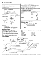
... right to seal exterior wall or roof opening around the cap. Vent Piece Equivalent Length 45° elbow 2.5 ft (0.8 m) 90° elbow 5.0 ft (1.5 m) IMPORTANT: Minimum distance "X": 24" (61 cm) from gas cooking surfaces. CABINET DIMENSIONS 36" (91.4 cm) for 36" models 48" (121.9 cm) for each vent piece used . 36" and 48" Hood Liner PRODUCT MODEL NUMBERS UXL6036Y UXL6048Y Electrical Requirements: A 120-volt, 60-Hz, AC-only, 15-amp, fused electrical circuit is used in the...
... right to seal exterior wall or roof opening around the cap. Vent Piece Equivalent Length 45° elbow 2.5 ft (0.8 m) 90° elbow 5.0 ft (1.5 m) IMPORTANT: Minimum distance "X": 24" (61 cm) from gas cooking surfaces. CABINET DIMENSIONS 36" (91.4 cm) for 36" models 48" (121.9 cm) for each vent piece used . 36" and 48" Hood Liner PRODUCT MODEL NUMBERS UXL6036Y UXL6048Y Electrical Requirements: A 120-volt, 60-Hz, AC-only, 15-amp, fused electrical circuit is used in the...

