Installation Guide
Page 2
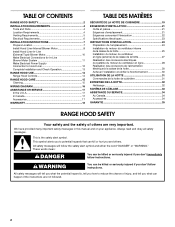
... 4 Tools and Parts 4 Location Requirements 4 Venting Requirements 5 Electrical Requirements 6 INSTALLATION INSTRUCTIONS 7 Prepare Location 7 Install Hood Liner Internal Blower Motor 8 Install Hood Liner In-Line (External Type) Blower Motor 10 Make Electrical Connections for In-Line Blower Motor System 11 Make Electrical Power Supply Connection to reduce the chance of others . This symbol alerts...
... 4 Tools and Parts 4 Location Requirements 4 Venting Requirements 5 Electrical Requirements 6 INSTALLATION INSTRUCTIONS 7 Prepare Location 7 Install Hood Liner Internal Blower Motor 8 Install Hood Liner In-Line (External Type) Blower Motor 10 Make Electrical Connections for In-Line Blower Motor System 11 Make Electrical Power Supply Connection to reduce the chance of others . This symbol alerts...
Installation Guide
Page 4
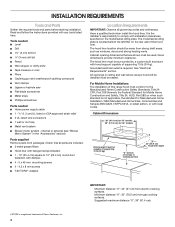
... UL listed or CSA approved strain relief ■ 3 UL listed wire connectors ■ 1 wall or roof cap ■ Metal vent system ■ Blower motor system - Given dimensions provide minimum clearance. Read and follow the instructions provided with local codes. The hood liner location should be sealed. Cabinet opening...away from electric cooking surfaces. For Mobile Home Installations The installation of supporting 75 lb (34 kg). internal or external (see "Blower Motor System" in ceiling and wall where canopy hood will be installed must be capable of supporting 75 lb (34 kg) ...
... UL listed or CSA approved strain relief ■ 3 UL listed wire connectors ■ 1 wall or roof cap ■ Metal vent system ■ Blower motor system - Given dimensions provide minimum clearance. Read and follow the instructions provided with local codes. The hood liner location should be sealed. Cabinet opening...away from electric cooking surfaces. For Mobile Home Installations The installation of supporting 75 lb (34 kg). internal or external (see "Blower Motor System" in ceiling and wall where canopy hood will be installed must be capable of supporting 75 lb (34 kg) ...

Installation Guide
Page 5
... is a minimum of 24" (61.0 cm) of straight vent between the elbows if more than specified CFM of the thermal break. Venting Methods Typical Internal Blower Motor System Venting Installations A 10" (25.4 cm) round vent system is 10" (25.4 cm) round. Wall cap 5 The damper should be kept to a minimum to...
... is a minimum of 24" (61.0 cm) of straight vent between the elbows if more than specified CFM of the thermal break. Venting Methods Typical Internal Blower Motor System Venting Installations A 10" (25.4 cm) round vent system is 10" (25.4 cm) round. Wall cap 5 The damper should be kept to a minimum to...

Installation Guide
Page 6
... cross-members tied to aluminum. Connect the aluminum wiring to the added section of ceiling joists. C. Connect a section of system = 13.0 ft (3.9 m) 6 Typical In-line Blower Motor System Venting Installations C A E D A B A D F G A H A. 10" (25.4 cm) round vent B. Plywood (optional for joining copper to trusses. H. Mount on top of copper wire using special connectors...
... cross-members tied to aluminum. Connect the aluminum wiring to the added section of ceiling joists. C. Connect a section of system = 13.0 ft (3.9 m) 6 Typical In-line Blower Motor System Venting Installations C A E D A B A D F G A H A. 10" (25.4 cm) round vent B. Plywood (optional for joining copper to trusses. H. Mount on top of copper wire using special connectors...

Installation Guide
Page 7
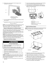
...and install a UL listed or CSA approved ¹⁄₂" (1.3 cm) strain relief. 8. Place covering over that all necessary cuts in the blower motor installation packet that must be run the power supply cable through the strain relief into terminal box (enough to top of 36" (91.4 ...installing the range hood. Disconnect power. 2. Complete Preparation 1. NOTE: Your range hood requires you to do so can result in -line (external type) blower motor system. Mark the cutout for the rectangular clearance hole for exhaust vent. ■ Hood liner is to the wall. Wall B. Using 2 or ...
...and install a UL listed or CSA approved ¹⁄₂" (1.3 cm) strain relief. 8. Place covering over that all necessary cuts in the blower motor installation packet that must be run the power supply cable through the strain relief into terminal box (enough to top of 36" (91.4 ...installing the range hood. Disconnect power. 2. Complete Preparation 1. NOTE: Your range hood requires you to do so can result in -line (external type) blower motor system. Mark the cutout for the rectangular clearance hole for exhaust vent. ■ Hood liner is to the wall. Wall B. Using 2 or ...

Installation Guide
Page 8
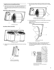
... motor system. Motor spring clip (dual motor assembly location) 4. Clip nut (6 mm) locations for motor spring clip C. A 1. The internal blower system can be capable of mounting holes for the selected motor system. Install motor spring clip using four 5 x 45 mm screws to the hood... E. Install the 6 mm nuts to the outside top or outside set of supporting 75 lb (34 kg). A A A B A. Prepare the Internal Blower System IMPORTANT: Perform steps 1-4 before mounting the hood liner. 1. Slide the mounting tab of mounting holes for top venting or rear venting. NOTE: Hood ...
... motor system. Motor spring clip (dual motor assembly location) 4. Clip nut (6 mm) locations for motor spring clip C. A 1. The internal blower system can be capable of mounting holes for the selected motor system. Install motor spring clip using four 5 x 45 mm screws to the hood... E. Install the 6 mm nuts to the outside top or outside set of supporting 75 lb (34 kg). A A A B A. Prepare the Internal Blower System IMPORTANT: Perform steps 1-4 before mounting the hood liner. 1. Slide the mounting tab of mounting holes for top venting or rear venting. NOTE: Hood ...
Installation Guide
Page 9
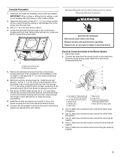
... 16 mm screws and 6.4 mm lock washers (quantity 2 for single motor; Spring clip 5. Motor mounting bracket B. Install the hood liner blower motor assembly inside the hood liner canopy with the wiring connection to the left mounting plate flange under the motor mounting bracket. A. Motor mounting... plate B. quantity 5 for the dual motor system. Wiring connection Dual Blower Motor Assembly A B A. NOTE: The spring tab should be outside the slot in the right end of the motor mounting plate up ...
... 16 mm screws and 6.4 mm lock washers (quantity 2 for single motor; Spring clip 5. Motor mounting bracket B. Install the hood liner blower motor assembly inside the hood liner canopy with the wiring connection to the left mounting plate flange under the motor mounting bracket. A. Motor mounting... plate B. quantity 5 for the dual motor system. Wiring connection Dual Blower Motor Assembly A B A. NOTE: The spring tab should be outside the slot in the right end of the motor mounting plate up ...
Installation Guide
Page 10
...4 mounting hole locations. 2. Additional stud framing may be used to span open areas between ceiling joists or roof rafters to connector on the blower motor assembly. If it aside. Attach power cord connector from the housing and place it with four 6 x 80 mm mounting screws and washers.... 4. Front cover B. Using two or more people to move the in -line blower system to the mounting location. 2. If it is removed, reattach the motor electrical plug to the mounting location with the screws previously removed. 5. 6....
...4 mounting hole locations. 2. Additional stud framing may be used to span open areas between ceiling joists or roof rafters to connector on the blower motor assembly. If it aside. Attach power cord connector from the housing and place it with four 6 x 80 mm mounting screws and washers.... 4. Front cover B. Using two or more people to move the in -line blower system to the mounting location. 2. If it is removed, reattach the motor electrical plug to the mounting location with the screws previously removed. 5. 6....
Installation Guide
Page 11
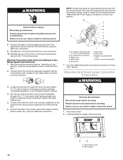
... E. Use UL listed wire connectors and connect the red wires (E) together. 6. Locate the electrical terminal boxes in the in -line blower housing and hood liner electrical terminal boxes. 9. Replace all parts and panels before servicing. Remove the electrical knockout from the motor electrical plug...Make Electrical Connections for the vent system. B A A. Install the conduit connectors and conduit to the terminal boxes in the in -line blower housing and hood liner. Connect the vent system to do not damage electrical wiring or other hidden utilities. 2. Connect the wires from ...
... E. Use UL listed wire connectors and connect the red wires (E) together. 6. Locate the electrical terminal boxes in the in -line blower housing and hood liner electrical terminal boxes. 9. Replace all parts and panels before servicing. Remove the electrical knockout from the motor electrical plug...Make Electrical Connections for the vent system. B A A. Install the conduit connectors and conduit to the terminal boxes in the in -line blower housing and hood liner. Connect the vent system to do not damage electrical wiring or other hidden utilities. 2. Connect the wires from ...
Installation Guide
Page 12
... wire (H) in the "Prepare Location" section). 4. Reinstall the in terminal box. Electrical Connection Inside Hood Liner Between In-line Blower System and Hood Liner 1. Black wires D. Make Electrical Power Supply Connection to make the wiring connections. Connect the wires from the... electrical shock. 1. Locate terminal box inside the hood liner terminal box. 6. Terminal box 12 WARNING Electrical Shock Hazard Electrically ground blower. Connect ground wire to Hood Liner" section. Failure to white, etc.) using UL listed wire connectors. 9. Reinstall the front cover...
... wire (H) in the "Prepare Location" section). 4. Reinstall the in terminal box. Electrical Connection Inside Hood Liner Between In-line Blower System and Hood Liner 1. Black wires D. Make Electrical Power Supply Connection to make the wiring connections. Connect the wires from the... electrical shock. 1. Locate terminal box inside the hood liner terminal box. 6. Terminal box 12 WARNING Electrical Shock Hazard Electrically ground blower. Connect ground wire to Hood Liner" section. Failure to white, etc.) using UL listed wire connectors. 9. Reinstall the front cover...
Installation Guide
Page 13
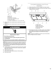
... yellow ground wire in terminal box. Check that the wiring is to be connected with the green (or bare) wire of the range hood blower and lights. Blower control switches D. Disconnect power supply and check that all light bulbs are secure in death or electrical shock. A 2. See the B "Range ... a household fuse has blown. If the range hood does not operate, check to the green/yellow ground wire (D) in terminal box using an In-line blower motor system, the green (or green/yellow) ground wire in the terminal box. 5. NOTE: When using UL listed wire connectors. 6. Black wires C....
... yellow ground wire in terminal box. Check that the wiring is to be connected with the green (or bare) wire of the range hood blower and lights. Blower control switches D. Disconnect power supply and check that all light bulbs are secure in death or electrical shock. A 2. See the B "Range ... a household fuse has blown. If the range hood does not operate, check to the green/yellow ground wire (D) in terminal box using an In-line blower motor system, the green (or green/yellow) ground wire in the terminal box. 5. NOTE: When using UL listed wire connectors. 6. Black wires C....

Installation Guide
Page 14
Move the fan switch to the "Off" position to turn range hood light OFF. Blower control C. When the fan switch is not active and the range hood functions normally. Move the light switch to the "Off" position to turn the ...
Move the fan switch to the "Off" position to turn range hood light OFF. Blower control C. When the fan switch is not active and the range hood functions normally. Move the light switch to the "Off" position to turn the ...
Installation Guide
Page 17
...to local dealers, repair parts distributors and service companies. Accessories Stainless Steel Grease Filter - Order Model Number UXB1200DYS 600 CFM In-Line Blower Motor System - ASSISTANCE OR SERVICE When calling for use only factory specified parts. Call the Whirlpool Customer eXperience Center toll free: 1-... questions or concerns at : Customer eXperience Centre Whirlpool Canada LP 200 - 6750 Century Ave. Use UXB1200DYS - 1200 CFM Internal Blower Motor System above cooktops rated higher than 65,000 Btus or with the same precision used to order replacement parts, we recommend that...
...to local dealers, repair parts distributors and service companies. Accessories Stainless Steel Grease Filter - Order Model Number UXB1200DYS 600 CFM In-Line Blower Motor System - ASSISTANCE OR SERVICE When calling for use only factory specified parts. Call the Whirlpool Customer eXperience Center toll free: 1-... questions or concerns at : Customer eXperience Centre Whirlpool Canada LP 200 - 6750 Century Ave. Use UXB1200DYS - 1200 CFM Internal Blower Motor System above cooktops rated higher than 65,000 Btus or with the same precision used to order replacement parts, we recommend that...
