

Installation Instructions
Page 1
... if the instructions are very important. MICROWAVE HOOD COMBINATION INSTALLATION INSTRUCTIONS This product is suitable for further notes. These installation instructions cover different models. See "Installation Requirements" section for use above electric or gas cooking... safety and the safety of Contents MICROWAVE HOOD COMBINATION SAFETY 1 INSTALLATION REQUIREMENTS 2 Tools and Parts 2 Remove Cardboard Template 2 Location Requirements 2 Product Dimensions 3 Electrical Requirements 3 INSTALLATION INSTRUCTIONS 4 Remove Mounting Plate 4 Rotate Blower Motor 4 Locate Wall...
... if the instructions are very important. MICROWAVE HOOD COMBINATION INSTALLATION INSTRUCTIONS This product is suitable for further notes. These installation instructions cover different models. See "Installation Requirements" section for use above electric or gas cooking... safety and the safety of Contents MICROWAVE HOOD COMBINATION SAFETY 1 INSTALLATION REQUIREMENTS 2 Tools and Parts 2 Remove Cardboard Template 2 Location Requirements 2 Product Dimensions 3 Electrical Requirements 3 INSTALLATION INSTRUCTIONS 4 Remove Mounting Plate 4 Rotate Blower Motor 4 Locate Wall...

Installation Instructions
Page 2
... for 1/4" x 2" lag screws ■ 1½" (3.8 cm) diam. See User Instructions.) NOTE: Depending on model, charcoal filters may be installed. See "Installation Dimensions" illustration. ■ Minimum one 2" x 4" (50.8 x 101.6 mm) wood wall stud and minimum 3/8" (10 mm) thickness drywall...Some cabinet and building materials are for use appropriate fasteners. Cut along the perforation to separate the template from the top of installation. Damper assembly (for weight of wall structures, be included. Sheet metal screws (2) G. Location Requirements Check the opening . ...
... for 1/4" x 2" lag screws ■ 1½" (3.8 cm) diam. See User Instructions.) NOTE: Depending on model, charcoal filters may be installed. See "Installation Dimensions" illustration. ■ Minimum one 2" x 4" (50.8 x 101.6 mm) wood wall stud and minimum 3/8" (10 mm) thickness drywall...Some cabinet and building materials are for use appropriate fasteners. Cut along the perforation to separate the template from the top of installation. Damper assembly (for weight of wall structures, be included. Sheet metal screws (2) G. Location Requirements Check the opening . ...

Installation Instructions
Page 3
... not use an adapter. Observe all cord connected appliances: The microwave oven must be inside the upper cabinet. The microwave oven is properly installed and grounded. The plug must be plugged into a grounded 3 prong outlet. If the power supply cord is properly grounded. A B ...a cord having a grounding wire with a fuse or circuit breaker. or 20-amp electrical supply with a grounding plug. A. 2" x 4" wall stud B. Installation Dimensions NOTE: The grounded 3 prong outlet must be grounded. Required: ■ A 120 Volt, 60 Hz, AC only, 15- Product Dimensions 17¹⁄...
... not use an adapter. Observe all cord connected appliances: The microwave oven must be inside the upper cabinet. The microwave oven is properly installed and grounded. The plug must be plugged into a grounded 3 prong outlet. If the power supply cord is properly grounded. A B ...a cord having a grounding wire with a fuse or circuit breaker. or 20-amp electrical supply with a grounding plug. A. 2" x 4" wall stud B. Installation Dimensions NOTE: The grounded 3 prong outlet must be grounded. Required: ■ A 120 Volt, 60 Hz, AC only, 15- Product Dimensions 17¹⁄...

Installation Instructions
Page 4
... oven, remove it and set it may be used. Remove screws attaching damper plate to the back of the microwave oven. Damper plate 2. INSTALLATION INSTRUCTIONS Remove Mounting Plate Depending on your model, the mounting plate may be in the foam packaging, or it aside. 3. Screws B. NOTE:... To avoid damage to back of microwave oven with 2 screws removed in recessed holes) D A. Wall Venting Installation Only 1. Remove 2 screws attaching blower motor to the microwave oven, do not grip or use the door or door handle while the microwave oven is...
... oven, remove it and set it may be used. Remove screws attaching damper plate to the back of the microwave oven. Damper plate 2. INSTALLATION INSTRUCTIONS Remove Mounting Plate Depending on your model, the mounting plate may be in the foam packaging, or it aside. 3. Screws B. NOTE:... To avoid damage to back of microwave oven with 2 screws removed in recessed holes) D A. Wall Venting Installation Only 1. Remove 2 screws attaching blower motor to the microwave oven, do not grip or use the door or door handle while the microwave oven is...

Installation Instructions
Page 5
... be reattached to back of microwave oven with 2 screws removed in Step 3 cannot be poor. Repeat Step 2 from "Wall Venting Installation Only." 5. Rotate blower motor so that exhaust ports face the top of microwave oven, and flat sides of blower motor face back ... into the slots in Step 3 of microwave oven. D A. Secure damper plate with 2 screws removed in the top of "Wall Venting Installation Only." 5 Roof Venting Installation Only 1. Reattach blower motor to the microwave oven. 7. Slots 8. A 6. Securely tighten screws. Make sure damper plate tabs are inserted ...
... be reattached to back of microwave oven with 2 screws removed in Step 3 cannot be poor. Repeat Step 2 from "Wall Venting Installation Only." 5. Rotate blower motor so that exhaust ports face the top of microwave oven, and flat sides of blower motor face back ... into the slots in Step 3 of microwave oven. D A. Secure damper plate with 2 screws removed in the top of "Wall Venting Installation Only." 5 Roof Venting Installation Only 1. Reattach blower motor to the microwave oven. 7. Slots 8. A 6. Securely tighten screws. Make sure damper plate tabs are inserted ...

Installation Instructions
Page 6
... 2 B C C C D B D A A A A E E E E F F NOTE: If wall stud is within the opening. Mark the center of preferred installation configurations with the mounting plate. Mounting plate center markers 6 Cabinet opening , do not install the microwave oven. 1. Support tabs F. Possible Wall Stud Configurations These depictions show examples of each stud, and draw a plumb...of the wall stud(s) within 6" (15.2 cm) of the vertical centerline (see "Mark Rear Wall" section), only recirculation or roof venting installation can be done. Holes for lag screws E. Wall stud centerlines D.
... 2 B C C C D B D A A A A E E E E F F NOTE: If wall stud is within the opening. Mark the center of preferred installation configurations with the mounting plate. Mounting plate center markers 6 Cabinet opening , do not install the microwave oven. 1. Support tabs F. Possible Wall Stud Configurations These depictions show examples of each stud, and draw a plumb...of the wall stud(s) within 6" (15.2 cm) of the vertical centerline (see "Mark Rear Wall" section), only recirculation or roof venting installation can be done. Holes for lag screws E. Wall stud centerlines D.

Installation Instructions
Page 7
... cardboard template in place, mark both sides of cardboard template must align with the dimensions described in the shaded areas are 3 installation configurations. The blackened holes in Step 4. Set the mounting plate aside. Mark the centerline 3/8" (1 cm) down from the ...the vertical centerline of the cutout area. 14. D A C B A. Rear wall B. These represent the mounting plate's end holes and bottom edge. 4. Wall Venting Installation Only Upper cabinet bottom ³⁄₈" (1 cm) 4" (10.2 cm) Centerline 6" (15.2 cm) 6" (15.2 cm) 8. Using measuring tape, measure...
... cardboard template in place, mark both sides of cardboard template must align with the dimensions described in the shaded areas are 3 installation configurations. The blackened holes in Step 4. Set the mounting plate aside. Mark the centerline 3/8" (1 cm) down from the ...the vertical centerline of the cutout area. 14. D A C B A. Rear wall B. These represent the mounting plate's end holes and bottom edge. 4. Wall Venting Installation Only Upper cabinet bottom ³⁄₈" (1 cm) 4" (10.2 cm) Centerline 6" (15.2 cm) 6" (15.2 cm) 8. Using measuring tape, measure...

Installation Instructions
Page 8
..., insert a 1/4-20 x 3" round-head bolt through the end hole that fits over the 3/4" (19 mm) hole drilled in Step 2 of "Installation for example, the thickness of "Mark Rear Wall." The template has trim lines to use as guides. ■ If the wall behind the microwave oven...(19 mm) hole through both end holes. 3. B D A. 1/4-20 x 3" round-head bolt B. Wall Studs at One End Hole (Figure 3) 1. Remove all lag screws and bolts. Installation for the toggle nut to go through the wall and to open . 3. Drill a 3/16" (5 mm) hole into both end holes of "Mark Rear Wall." 2. With...
..., insert a 1/4-20 x 3" round-head bolt through the end hole that fits over the 3/4" (19 mm) hole drilled in Step 2 of "Installation for example, the thickness of "Mark Rear Wall." The template has trim lines to use as guides. ■ If the wall behind the microwave oven...(19 mm) hole through both end holes. 3. B D A. 1/4-20 x 3" round-head bolt B. Wall Studs at One End Hole (Figure 3) 1. Remove all lag screws and bolts. Installation for the toggle nut to go through the wall and to open . 3. Drill a 3/16" (5 mm) hole into both end holes of "Mark Rear Wall." 2. With...

Installation Instructions
Page 9
... NOTE: To avoid damage to the upper cabinet. Back of the microwave oven is metal, the supply cord bushing needs to move and install microwave oven. Rotate microwave oven up toward upper cabinet. Check that the damper blade hinge is closed and taped shut. 3. Sheet metal ...screws 3. 5. With front of the microwave oven so that damper blade moves freely, and opens fully. 2. For Roof Venting Installation Only 7. B A A. Drill 3/8" (10 mm) holes at points "D" and "E" on the back of microwave oven still tilted, thread power supply cord ...
... NOTE: To avoid damage to the upper cabinet. Back of the microwave oven is metal, the supply cord bushing needs to move and install microwave oven. Rotate microwave oven up toward upper cabinet. Check that the damper blade hinge is closed and taped shut. 3. Sheet metal ...screws 3. 5. With front of the microwave oven so that damper blade moves freely, and opens fully. 2. For Roof Venting Installation Only 7. B A A. Drill 3/8" (10 mm) holes at points "D" and "E" on the back of microwave oven still tilted, thread power supply cord ...

Installation Instructions
Page 10
...warp the top of 1 minute at least one person holding it in death, fire, or electrical shock. 2. To avoid warping, wood filler blocks (installer to damper assembly. A B A. Do not use an extension cord. Reconnect power. 4. Using 2 or more people, lift microwave oven off of...secure with at 100% power. If the problem continues, call an electrician. ■ Check that a circuit breaker has not tripped. Save Installation Instructions for filter placement. Damper assembly (under the raised tabs of mounting plate, and set aside on the turntable, and programming a cook ...
...warp the top of 1 minute at least one person holding it in death, fire, or electrical shock. 2. To avoid warping, wood filler blocks (installer to damper assembly. A B A. Do not use an extension cord. Reconnect power. 4. Using 2 or more people, lift microwave oven off of...secure with at 100% power. If the problem continues, call an electrician. ■ Check that a circuit breaker has not tripped. Save Installation Instructions for filter placement. Damper assembly (under the raised tabs of mounting plate, and set aside on the turntable, and programming a cook ...
Installation Instructions
Page 11
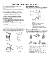
... "Rectangular to round transition piece so that the damper can open fully. diameter round vent C. See the examples in the vent system ■ using recirculation installation. Roof cap: 3¹⁄₄" x 10" = 24 ft (8.3 x 25.4 cm = 7.3 m) C. 90° elbow: 3¹ ₄" x 10" = 25 ft ... ft (15.2 cm = 1.5 m) G. 90° flat elbow: 3¹⁄₄" x 10" = 10 ft (8.3 x 25.4 cm = 3 m) 11 For optimal venting installation, we recommend: ■ using roof or wall caps that there is intended for use when figuring vent length. NOTES: ■ Vent materials needed for...
... "Rectangular to round transition piece so that the damper can open fully. diameter round vent C. See the examples in the vent system ■ using recirculation installation. Roof cap: 3¹⁄₄" x 10" = 24 ft (8.3 x 25.4 cm = 7.3 m) C. 90° elbow: 3¹ ₄" x 10" = 25 ft ... ft (15.2 cm = 1.5 m) G. 90° flat elbow: 3¹⁄₄" x 10" = 10 ft (8.3 x 25.4 cm = 3 m) 11 For optimal venting installation, we recommend: ■ using roof or wall caps that there is intended for use when figuring vent length. NOTES: ■ Vent materials needed for...

Installation Instructions
Page 12
...A 3¹⁄₄" x 10" (8.3 x 25.4 cm) rectangular or 6" (15.2 cm) round vent should be used . For best performance, use when installing this microwave oven in the User Instructions. Each panel is a list of the vent system including straight vent, elbow(s), transitions and wall or roof caps...listed in a 36" (91.4 cm) or 42" (106.7 cm) wide opening , behind the microwave oven door on the front facing of the installation hardware needs to use no more than three 90° elbows. The total length of available replacement parts. In addition, a rectangular 3" (7.6 cm)...
...A 3¹⁄₄" x 10" (8.3 x 25.4 cm) rectangular or 6" (15.2 cm) round vent should be used . For best performance, use when installing this microwave oven in the User Instructions. Each panel is a list of the vent system including straight vent, elbow(s), transitions and wall or roof caps...listed in a 36" (91.4 cm) or 42" (106.7 cm) wide opening , behind the microwave oven door on the front facing of the installation hardware needs to use no more than three 90° elbows. The total length of available replacement parts. In addition, a rectangular 3" (7.6 cm)...
Owners Manual
Page 1
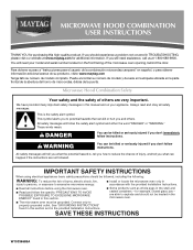
... mean: DANGER You can happen if the instructions are able to excessive microwave energy: ■ Install or locate the microwave oven only in accordance with the provided Installation Instructions. ■ Read all safety messages. IMPORTANT SAFETY INSTRUCTIONS When using the microwave oven. ■...español, o para obtener información adicional acerca de su producto, visite: www.maytag.com Tenga listo su número de modelo completo. for purchasing this section and in the provided Installation Instructions. All safety messages will tell you don't follow instructions.
... mean: DANGER You can happen if the instructions are able to excessive microwave energy: ■ Install or locate the microwave oven only in accordance with the provided Installation Instructions. ■ Read all safety messages. IMPORTANT SAFETY INSTRUCTIONS When using the microwave oven. ■...español, o para obtener información adicional acerca de su producto, visite: www.maytag.com Tenga listo su número de modelo completo. for purchasing this section and in the provided Installation Instructions. All safety messages will tell you don't follow instructions.
Owners Manual
Page 3
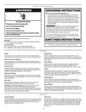
... Tray Use the rectangular cooking rack only for only 30 minutes more (off . To avoid damage to whether the microwave oven is properly installed and grounded. This is equipped with a cord having a grounding wire with plates that is properly grounded. Do not use an extension cord... the Start control to soil buildup, clean rack supports often. Settings Clock Light Timer The Clock is too short, have a qualified electrician or serviceman install an outlet near the microwave oven. Filter Reset Reset the filter status after 2-level cooking. Required: ■ A 120 Volt, 60 Hz, AC...
... Tray Use the rectangular cooking rack only for only 30 minutes more (off . To avoid damage to whether the microwave oven is properly installed and grounded. This is equipped with a cord having a grounding wire with plates that is properly grounded. Do not use an extension cord... the Start control to soil buildup, clean rack supports often. Settings Clock Light Timer The Clock is too short, have a qualified electrician or serviceman install an outlet near the microwave oven. Filter Reset Reset the filter status after 2-level cooking. Required: ■ A 120 Volt, 60 Hz, AC...
Owners Manual
Page 4
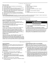
..., if desired, and start the microwave oven. Always follow a cooking cycle. To avoid damage to the microwave oven caused by itself or can be changed . Installing/Replacing Filters and Light Bulbs NOTE: A filter status indicator (on the underside of cook time at least 30 minutes after cooking. See "Settings" section to...
..., if desired, and start the microwave oven. Always follow a cooking cycle. To avoid damage to the microwave oven caused by itself or can be changed . Installing/Replacing Filters and Light Bulbs NOTE: A filter status indicator (on the underside of cook time at least 30 minutes after cooking. See "Settings" section to...

Owners Manual
Page 6
.... Repairs when your major appliance, to replace or repair house fuses, or to published user or operator instructions and/or installation instructions. 4. MAYTAG SHALL NOT BE LIABLE FOR INCIDENTAL OR CONSEQUENTIAL DAMAGES. Please keep this User Instructions and model number information for a factory ... attached to the finish of your major appliance for other rights that vary from state to state or province to Maytag with published installation instructions. 11. EXCLUSION OF INCIDENTAL AND CONSEQUENTIAL DAMAGES YOUR SOLE AND EXCLUSIVE REMEDY UNDER THIS LIMITED WARRANTY SHALL BE...
.... Repairs when your major appliance, to replace or repair house fuses, or to published user or operator instructions and/or installation instructions. 4. MAYTAG SHALL NOT BE LIABLE FOR INCIDENTAL OR CONSEQUENTIAL DAMAGES. Please keep this User Instructions and model number information for a factory ... attached to the finish of your major appliance for other rights that vary from state to state or province to Maytag with published installation instructions. 11. EXCLUSION OF INCIDENTAL AND CONSEQUENTIAL DAMAGES YOUR SOLE AND EXCLUSIVE REMEDY UNDER THIS LIMITED WARRANTY SHALL BE...
Dimension Guide
Page 1
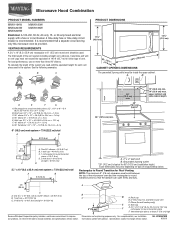
... transition piece: 3 " x 10" to 6" = 5 ft (8.3 x 25.4 cm to change materials and specifications without notice. For complete details, see Installation our products, we reserve the right to improve Dimensions are for 66" (167.6 cm) installation height. Specifications subject to 15.2 cm = 1.5 m) B. or 20-amp fused electrical supply with product. Grounded 3-prong outlet *30...
... transition piece: 3 " x 10" to 6" = 5 ft (8.3 x 25.4 cm to change materials and specifications without notice. For complete details, see Installation our products, we reserve the right to improve Dimensions are for 66" (167.6 cm) installation height. Specifications subject to 15.2 cm = 1.5 m) B. or 20-amp fused electrical supply with product. Grounded 3-prong outlet *30...
Warranty Information
Page 1
..., misuse, abuse, fire, flood, acts of God, improper installation, installation not in accordance with electrical or plumbing codes, or use of consumables or cleaning products not approved by an authorized Maytag servicer is not available. 10. Expenses for travel and transportation ... THROUGH TENTH YEAR LIMITED WARRANTY (MAGNETRON ONLY - Proof of original purchase date is installed, operated and maintained according to instructions attached to or furnished with the product, Maytag will pay for a factory specified replacement Magnetron to correct non-cosmetic defects in materials...
..., misuse, abuse, fire, flood, acts of God, improper installation, installation not in accordance with electrical or plumbing codes, or use of consumables or cleaning products not approved by an authorized Maytag servicer is not available. 10. Expenses for travel and transportation ... THROUGH TENTH YEAR LIMITED WARRANTY (MAGNETRON ONLY - Proof of original purchase date is installed, operated and maintained according to instructions attached to or furnished with the product, Maytag will pay for a factory specified replacement Magnetron to correct non-cosmetic defects in materials...


