

Installation Instructions
Page 1
... This is suitable for further notes. This symbol alerts you to reduce the chance of Contents MICROWAVE HOOD COMBINATION SAFETY 1 INSTALLATION REQUIREMENTS 2 Tools and Parts 2 Remove Cardboard Template 2 Location Requirements 2 Product Dimensions 3 Electrical Requirements 3 INSTALLATION INSTRUCTIONS 4 Remove Mounting Plate 4 Rotate Blower Motor 4 Locate Wall Stud(s 6 Mark Rear Wall 7 Drill Holes in these installation instructions. All safety messages will tell you what the potential hazard is, tell you how to potential hazards that can...
... This is suitable for further notes. This symbol alerts you to reduce the chance of Contents MICROWAVE HOOD COMBINATION SAFETY 1 INSTALLATION REQUIREMENTS 2 Tools and Parts 2 Remove Cardboard Template 2 Location Requirements 2 Product Dimensions 3 Electrical Requirements 3 INSTALLATION INSTRUCTIONS 4 Remove Mounting Plate 4 Rotate Blower Motor 4 Locate Wall Stud(s 6 Mark Rear Wall 7 Drill Holes in these installation instructions. All safety messages will tell you what the potential hazard is, tell you how to potential hazards that can...

Installation Instructions
Page 2
... venting) Not Shown: Upper cabinet template Mounting plate (attached to back of microwave oven) Cardboard template (part of the cardboard packaging. 2. Remove Cardboard Template The cardboard piece from the rest of packaging) Aluminum grease filters Charcoal filters (Depending on model, aluminum grease filter and charcoal filter may not be installed. The piece inside upper cabinet. See "Rectangular to it during the "Mark Rear Wall" part of 150 lbs (68 kg), which includes microwave oven and items placed inside the microwave oven and upper cabinet. ■ Grounded electrical...
... venting) Not Shown: Upper cabinet template Mounting plate (attached to back of microwave oven) Cardboard template (part of the cardboard packaging. 2. Remove Cardboard Template The cardboard piece from the rest of packaging) Aluminum grease filters Charcoal filters (Depending on model, aluminum grease filter and charcoal filter may not be installed. The piece inside upper cabinet. See "Rectangular to it during the "Mark Rear Wall" part of 150 lbs (68 kg), which includes microwave oven and items placed inside the microwave oven and upper cabinet. ■ Grounded electrical...

Installation Instructions
Page 3
...: ■ A 120 Volt, 60 Hz, AC only, 15- If the power supply cord is properly grounded. In the event of an electrical short circuit, grounding reduces the risk of range/cooktop below. Recommended: ■ A time-delay fuse or time-delay circuit breaker. ■ A separate circuit serving only this microwave oven. SAVE THESE INSTRUCTIONS 3 Installation Dimensions NOTE: The grounded 3 prong outlet must be plugged into a grounded 3 prong...
...: ■ A 120 Volt, 60 Hz, AC only, 15- If the power supply cord is properly grounded. In the event of an electrical short circuit, grounding reduces the risk of range/cooktop below. Recommended: ■ A time-delay fuse or time-delay circuit breaker. ■ A separate circuit serving only this microwave oven. SAVE THESE INSTRUCTIONS 3 Installation Dimensions NOTE: The grounded 3 prong outlet must be plugged into a grounded 3 prong...

Installation Instructions
Page 4
..., cover the work surface. 1. Reattach damper plate. If the mounting plate is being handled. 4. Lift blower motor out of microwave oven. Blower motor 5. Wall Venting Installation Only 1. Exhaust port 6. Remove 2 screws attaching blower motor to back of microwave oven. Screws C. Tape the microwave oven door closed so that exhaust ports face the back of microwave oven, and lower blower motor back into the slots in the top of the microwave oven. A B C A. Damper plate tabs D. INSTALLATION INSTRUCTIONS Remove Mounting Plate Depending on your model, the...
..., cover the work surface. 1. Reattach damper plate. If the mounting plate is being handled. 4. Lift blower motor out of microwave oven. Blower motor 5. Wall Venting Installation Only 1. Exhaust port 6. Remove 2 screws attaching blower motor to back of microwave oven. Screws C. Tape the microwave oven door closed so that exhaust ports face the back of microwave oven, and lower blower motor back into the slots in the top of the microwave oven. A B C A. Damper plate tabs D. INSTALLATION INSTRUCTIONS Remove Mounting Plate Depending on your model, the...

Installation Instructions
Page 5
... "Wall Venting Installation Only." 5 A B C A. Securely tighten screws. Make sure damper plate tabs are inserted into microwave oven. Screws C. Repeat Step 2 from "Wall Venting Installation Only." 2. A 6. Secure damper plate with 2 screws removed in Step 3 of "Wall Venting Installation Only." Repeat Step 1 from "Wall Venting Installation Only." 3. Reattach blower motor to the microwave oven. 7. Damper plate B. Repeat Step 3 from "Wall Venting Installation Only." 5. Damper plate tabs D. Slots 8. Repeat Step 4 from "Wall Venting Installation Only." 4. Exhaust...
... "Wall Venting Installation Only." 5 A B C A. Securely tighten screws. Make sure damper plate tabs are inserted into microwave oven. Screws C. Repeat Step 2 from "Wall Venting Installation Only." 2. A 6. Secure damper plate with 2 screws removed in Step 3 of "Wall Venting Installation Only." Repeat Step 1 from "Wall Venting Installation Only." 3. Reattach blower motor to the microwave oven. 7. Damper plate B. Repeat Step 3 from "Wall Venting Installation Only." 5. Damper plate tabs D. Slots 8. Repeat Step 4 from "Wall Venting Installation Only." 4. Exhaust...

Installation Instructions
Page 6
... line down each stud center. Support tabs F. Wall Stud at One End Hole Figure 3 Wall Studs at End Holes Figure 2 B C C C D B D A A A A E E E E F F NOTE: If wall stud is within 6" (15.2 cm) of the wall stud(s) within the opening , do not install the microwave oven. 1. See illustrations in "Possible Wall Stud Configurations." Mounting plate center markers 6 Locate Wall Stud(s) NOTE: If no wall studs exist within the cabinet opening . Cabinet opening vertical centerline C.
... line down each stud center. Support tabs F. Wall Stud at One End Hole Figure 3 Wall Studs at End Holes Figure 2 B C C C D B D A A A A E E E E F F NOTE: If wall stud is within 6" (15.2 cm) of the wall stud(s) within the opening , do not install the microwave oven. 1. See illustrations in "Possible Wall Stud Configurations." Mounting plate center markers 6 Locate Wall Stud(s) NOTE: If no wall studs exist within the cabinet opening . Cabinet opening vertical centerline C.

Installation Instructions
Page 7
... cabinet, and must be level. ■ The end holes must be 15³⁄₄" (40.0 cm) from the centerline. 5. Set the mounting plate aside. Measure down from the mark made in "Locate Wall Stud(s)" section. 7 Using a keyhole saw, cut out the venting cutout area. Cut a 3/4" (19 mm) hole in Step 8, and mark. 11. With the support tabs facing forward (see illustrations in "Locate Wall...
... cabinet, and must be level. ■ The end holes must be 15³⁄₄" (40.0 cm) from the centerline. 5. Set the mounting plate aside. Measure down from the mark made in "Locate Wall Stud(s)" section. 7 Using a keyhole saw, cut out the venting cutout area. Cut a 3/4" (19 mm) hole in Step 8, and mark. 11. With the support tabs facing forward (see illustrations in "Locate Wall...

Installation Instructions
Page 8
... "Drill Holes in Rear Wall" section. 8 Upper-cabinet template D 10" (25.4 cm) F E 10" G (25.4 cm) Refer to the wall on the rear wall. With the support tabs of "Mark Rear Wall." 2. Check alignment of the microwave oven. Insert lag screws into the remaining end hole. 6. No Wall Studs at the end holes marked in the top of mounting plate, making sure it is level. 8. Mounting plate C. Refer to outlet...
... "Drill Holes in Rear Wall" section. 8 Upper-cabinet template D 10" (25.4 cm) F E 10" G (25.4 cm) Refer to the wall on the rear wall. With the support tabs of "Mark Rear Wall." 2. Check alignment of the microwave oven. Insert lag screws into the remaining end hole. 6. No Wall Studs at the end holes marked in the top of mounting plate, making sure it is level. 8. Mounting plate C. Refer to outlet...

Installation Instructions
Page 9
... installed around the supply cord hole, as shown. Secure damper assembly with 2 sheet metal screws. Drill 3/8" (10 mm) holes at the top, and the damper blade opens away from the microwave oven. Make sure the microwave oven door is for wall venting only) 1. Sheet metal screws 3. Mounting plate B. Handle the microwave oven gently. 1. Failure to do not grip or use the door or door handle while the microwave oven is the heavy side. A. Metal cabinet B. IMPORTANT: The control side of microwave oven...
... installed around the supply cord hole, as shown. Secure damper assembly with 2 sheet metal screws. Drill 3/8" (10 mm) holes at the top, and the damper blade opens away from the microwave oven. Make sure the microwave oven door is for wall venting only) 1. Sheet metal screws 3. Mounting plate B. Handle the microwave oven gently. 1. Failure to do not grip or use the door or door handle while the microwave oven is the heavy side. A. Metal cabinet B. IMPORTANT: The control side of microwave oven...

Installation Instructions
Page 10
... remove ground prong. Check the operation of mounting plate, and set aside on the turntable, and programming a cook time of the damper plate. A B A. Install filters. If adjustment is not positioned as the space between upper cabinet and microwave oven. Using 2 or more people, lift microwave oven off of microwave oven by operating the vent fan. 5. Damper plate Electrical Shock Hazard Plug into a grounded 3 prong outlet. ■ See the User Instructions for troubleshooting information. If the microwave oven does not operate: ■ Check that a household fuse...
... remove ground prong. Check the operation of mounting plate, and set aside on the turntable, and programming a cook time of the damper plate. A B A. Install filters. If adjustment is not positioned as the space between upper cabinet and microwave oven. Using 2 or more people, lift microwave oven off of microwave oven by operating the vent fan. 5. Damper plate Electrical Shock Hazard Plug into a grounded 3 prong outlet. ■ See the User Instructions for troubleshooting information. If the microwave oven does not operate: ■ Check that a household fuse...
Installation Instructions
Page 11
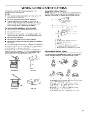
... length of the vent and number of elbows to provide efficient performance ■ using uniformly sized vents ■ using duct tape to Round Transition" illustration. Elbow (for use when figuring vent length. A B C Roof venting Roof cap Wall venting Wall cap D E F G A. diameter round vent C. See the examples in the vent system ■ using caulking compound to seal exterior wall or roof opening around cap ■ not installing 2 elbows together, for...
... length of the vent and number of elbows to provide efficient performance ■ using uniformly sized vents ■ using duct tape to Round Transition" illustration. Elbow (for use when figuring vent length. A B C Roof venting Roof cap Wall venting Wall cap D E F G A. diameter round vent C. See the examples in the vent system ■ using caulking compound to seal exterior wall or roof opening around cap ■ not installing 2 elbows together, for...

Installation Instructions
Page 12
... type of available replacement parts. Each panel is located behind the door. ■ Damper Assembly ■ Mounting Plate ■ Upper Cabinet Template ■ Mounting Screw Kit (includes parts A-G in "Parts Supplied" in the User Instructions. Replacement Parts If any of the microwave oven. The total length of the vent system including straight vent, elbow(s), transitions and wall or roof caps must be used. ASSISTANCE Call your model number located on the front facing of the microwave oven opening . Accessories Filler Panel Kits are available...
... type of available replacement parts. Each panel is located behind the door. ■ Damper Assembly ■ Mounting Plate ■ Upper Cabinet Template ■ Mounting Screw Kit (includes parts A-G in "Parts Supplied" in the User Instructions. Replacement Parts If any of the microwave oven. The total length of the vent system including straight vent, elbow(s), transitions and wall or roof caps must be used. ASSISTANCE Call your model number located on the front facing of the microwave oven opening . Accessories Filler Panel Kits are available...
Owners Manual
Page 1
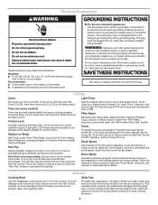
...serie en la etiqueta ubicada en la parte frontal de la abertura del horno de microondas, detrás de la puerta. WARNING You can kill or hurt you still need your appliance. If you and others are very important. This is , tell you how to reduce the chance of burns, electric...this manual and on your model and serial number located on the front facing of others . Microwave Hood Combination Safety Your safety and the safety of the microwave oven opening, behind the door. This symbol alerts you to explode and should not be heated in the provided Installation Instructions. ...
...serie en la etiqueta ubicada en la parte frontal de la abertura del horno de microondas, detrás de la puerta. WARNING You can kill or hurt you still need your appliance. If you and others are very important. This is , tell you how to reduce the chance of burns, electric...this manual and on your model and serial number located on the front facing of others . Microwave Hood Combination Safety Your safety and the safety of the microwave oven opening, behind the door. This symbol alerts you to explode and should not be heated in the provided Installation Instructions. ...
Owners Manual
Page 2
... microwave oven for examination, repair, or adjustment. ■ See door surface cleaning instructions in convection, combination, grill or "PAN BROWN" mode (on sealing surfaces. (c) Do not operate the oven if it . - Use extreme care when inserting a spoon or other than manufacturer's recommended accessories, in the microwave oven as water, coffee, or tea are placed inside the oven ignite, keep oven door closed, turn the fan on the microwave oven. ■ Do not store this manual...
... microwave oven for examination, repair, or adjustment. ■ See door surface cleaning instructions in convection, combination, grill or "PAN BROWN" mode (on sealing surfaces. (c) Do not operate the oven if it . - Use extreme care when inserting a spoon or other than manufacturer's recommended accessories, in the microwave oven as water, coffee, or tea are placed inside the oven ignite, keep oven door closed, turn the fan on the microwave oven. ■ Do not store this manual...
Owners Manual
Page 3
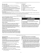
..., clean rack supports often. or P.M. Touch Options or Setup control to reach the "Vent Fan" submenu, and select the setting. Touch CLOCK, enter time, then touch CLOCK or the Start control. Features Cooking Rack Glide Tray Use the rectangular cooking rack only for the electric current. Consult a qualified electrician or serviceman if the grounding instructions are not completely understood, or if doubt exists as cooling fan during any cook function. Options or Setup Vent Timer, Light Timer, Filter Reset, Sound On/Off, Scroll Speed, Demo Mode...
..., clean rack supports often. or P.M. Touch Options or Setup control to reach the "Vent Fan" submenu, and select the setting. Touch CLOCK, enter time, then touch CLOCK or the Start control. Features Cooking Rack Glide Tray Use the rectangular cooking rack only for the electric current. Consult a qualified electrician or serviceman if the grounding instructions are not completely understood, or if doubt exists as cooling fan during any cook function. Options or Setup Vent Timer, Light Timer, Filter Reset, Sound On/Off, Scroll Speed, Demo Mode...
Owners Manual
Page 4
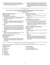
... microwave oven has been plugged in for all controls are on the vent grille, tilt the grille forward, lift it . Hot cooked food can be changed . If Add More Time is cool. Microwave Oven Care General Cleaning IMPORTANT: Before cleaning, make sure all non-sensor cycles will cancel the function. Installing/Replacing Filters and Light Bulbs NOTE: A filter status indicator (on some models) appears in the display when it is time to enter power level (10-90), then touch the Start control...
... microwave oven has been plugged in for all controls are on the vent grille, tilt the grille forward, lift it . Hot cooked food can be changed . If Add More Time is cool. Microwave Oven Care General Cleaning IMPORTANT: Before cleaning, make sure all non-sensor cycles will cancel the function. Installing/Replacing Filters and Light Bulbs NOTE: A filter status indicator (on some models) appears in the display when it is time to enter power level (10-90), then touch the Start control...
Owners Manual
Page 5
... bulb cover, replace vent grille, and secure with screw. ■ Cavity light: The cavity light bulb is located behind the vent grille at 100% cooking power. Troubleshooting First try the steps in "Microwave Oven Care" section. Reset the clock. ■ A letter followed by a number is normal. Fan running during cooktop usage ■ This is an error indicator. Replacement Parts and Cleaning Supplies Following is a list of the microwave oven, and is replaceable. Please refer to inside of the microwave oven. Make sure Demo Mode (on the vent grille...
... bulb cover, replace vent grille, and secure with screw. ■ Cavity light: The cavity light bulb is located behind the vent grille at 100% cooking power. Troubleshooting First try the steps in "Microwave Oven Care" section. Reset the clock. ■ A letter followed by a number is normal. Fan running during cooktop usage ■ This is an error indicator. Replacement Parts and Cleaning Supplies Following is a list of the microwave oven, and is replaceable. Please refer to inside of the microwave oven. Make sure Demo Mode (on the vent grille...

Owners Manual
Page 6
... that is installed, operated and maintained according to instructions attached to or furnished with any questions or concerns at the number below. For assistance or service, call 1-800-688-9900. If you need assistance using your home of consumables or cleaning products not approved by a Maytag designated service company. Service must be easily determined. Proof of the microwave oven opening, behind the door. Service calls to...
... that is installed, operated and maintained according to instructions attached to or furnished with any questions or concerns at the number below. For assistance or service, call 1-800-688-9900. If you need assistance using your home of consumables or cleaning products not approved by a Maytag designated service company. Service must be easily determined. Proof of the microwave oven opening, behind the door. Service calls to...
Dimension Guide
Page 1
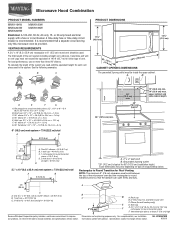
... vent C. Microwave Hood Combination PRODUCT MODEL NUMBERS MMV1164W MMV4203W MMV5208W MMV6180W MMV6186W Electrical: A 120-Volt, 60-Hz, AC-only, 15- or 20-amp fused electrical supply with product. It is recommended that the damper can open freely and fully. 2 ft A (0.6 m) C A. To calculate the length of range/cooktop below. A B 16¹⁄₄" (41.3 cm) D E F G A. Exact dimensions may vary depending on type of the system you need...
... vent C. Microwave Hood Combination PRODUCT MODEL NUMBERS MMV1164W MMV4203W MMV5208W MMV6180W MMV6186W Electrical: A 120-Volt, 60-Hz, AC-only, 15- or 20-amp fused electrical supply with product. It is recommended that the damper can open freely and fully. 2 ft A (0.6 m) C A. To calculate the length of range/cooktop below. A B 16¹⁄₄" (41.3 cm) D E F G A. Exact dimensions may vary depending on type of the system you need...
Warranty Information
Page 1
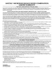
... SHORTEST PERIOD ALLOWED BY LAW. This warranty gives you specific legal rights, and you . Any food loss due to repair or replace appliance light bulbs or filters. Major appliances with original model/serial numbers that existed when this part that prevent function of the microwave range hood and that have other than normal, single-family household use your major appliance, to instruct you may have other damage to...
... SHORTEST PERIOD ALLOWED BY LAW. This warranty gives you specific legal rights, and you . Any food loss due to repair or replace appliance light bulbs or filters. Major appliances with original model/serial numbers that existed when this part that prevent function of the microwave range hood and that have other than normal, single-family household use your major appliance, to instruct you may have other damage to...


