

Installation Guide
Page 1
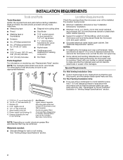
...if you what the potential hazard is, tell you how to Wall 8 Prepare Upper Cabinet 8 Install Damper Assembly 9 Install the Microwave Oven 9 Complete Installation 10 VENTING DESIGN SPECIFICATIONS 11 ASSISTANCE 12 Replacement Parts 12 Accessories 12 MICROWAVE HOOD COMBINATION SAFETY Your...words mean: DANGER You can kill or hurt you don't follow instructions. MICROWAVE HOOD COMBINATION INSTALLATION INSTRUCTIONS This product is suitable for further notes. See "Installation Requirements" section for use above electric or gas cooking products up to potential hazards that can ...
...if you what the potential hazard is, tell you how to Wall 8 Prepare Upper Cabinet 8 Install Damper Assembly 9 Install the Microwave Oven 9 Complete Installation 10 VENTING DESIGN SPECIFICATIONS 11 ASSISTANCE 12 Replacement Parts 12 Accessories 12 MICROWAVE HOOD COMBINATION SAFETY Your...words mean: DANGER You can kill or hurt you don't follow instructions. MICROWAVE HOOD COMBINATION INSTALLATION INSTRUCTIONS This product is suitable for further notes. See "Installation Requirements" section for use above electric or gas cooking products up to potential hazards that can ...
Installation Guide
Page 2
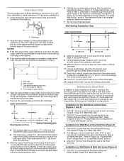
... (19 mm) hole saw ■■ Duct tape Parts Supplied: For information on reordering, see "Replacement Parts" section. For Roof Venting Installation Only: ■■ If you are using a rectangular to round transition piece, the 3" (7.6 cm) clearance needs to exist above the ...kg), which includes microwave oven and items placed inside the microwave oven and upper cabinet. ■■ Grounded electrical outlet inside upper cabinet. See "Installation Dimensions" illustration. ■■ Minimum one 2" x 4" (50.8 x 101.6 mm) wood wall stud and minimum 3/8" (10 mm) thickness...
... (19 mm) hole saw ■■ Duct tape Parts Supplied: For information on reordering, see "Replacement Parts" section. For Roof Venting Installation Only: ■■ If you are using a rectangular to round transition piece, the 3" (7.6 cm) clearance needs to exist above the ...kg), which includes microwave oven and items placed inside the microwave oven and upper cabinet. ■■ Grounded electrical outlet inside upper cabinet. See "Installation Dimensions" illustration. ■■ Minimum one 2" x 4" (50.8 x 101.6 mm) wood wall stud and minimum 3/8" (10 mm) thickness...

Installation Guide
Page 3
...power supply cord is properly grounded. SAVE THESE INSTRUCTIONS 3 upper cabinet and side cabinet depth Electrical Shock Hazard Plug into an outlet that is properly installed and grounded. Required: ■■ A 120 volt, 60 Hz, AC only, 15- Failure to whether the microwave oven is too short,... have a qualified electrician or serviceman install an outlet near the microwave oven. Grounded 3 prong outlet *30" (76.2 cm) is equipped with a cord having a grounding wire with a fuse or ...
...power supply cord is properly grounded. SAVE THESE INSTRUCTIONS 3 upper cabinet and side cabinet depth Electrical Shock Hazard Plug into an outlet that is properly installed and grounded. Required: ■■ A 120 volt, 60 Hz, AC only, 15- Failure to whether the microwave oven is too short,... have a qualified electrician or serviceman install an outlet near the microwave oven. Grounded 3 prong outlet *30" (76.2 cm) is equipped with a cord having a grounding wire with a fuse or ...
Installation Guide
Page 4
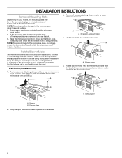
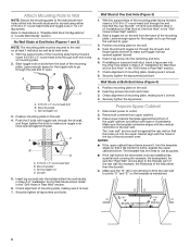
... set it may be attached to the back of microwave oven. For wall or roof venting, changes must be used. Exhaust port A. Wall Venting Installation Only 1. Remove screws attaching damper plate to the venting system. A A. Damper plate 2. Keep the damper assembly in case the venting method is... changed or the microwave oven is being handled. Screws B. Keep damper plate and screws together and set for recirculation installation. NOTE: To avoid possible damage to the microwave oven, do not grip or use the door or door handle while the microwave oven...
... set it may be attached to the back of microwave oven. For wall or roof venting, changes must be used. Exhaust port A. Wall Venting Installation Only 1. Remove screws attaching damper plate to the venting system. A A. Damper plate 2. Keep the damper assembly in case the venting method is... changed or the microwave oven is being handled. Screws B. Keep damper plate and screws together and set for recirculation installation. NOTE: To avoid possible damage to the microwave oven, do not grip or use the door or door handle while the microwave oven...
Installation Guide
Page 5
...not positioned with flat sides facing the back of the microwave oven (as shown), performance will be reattached to 4 from "Wall Venting Installation Only." 2. Damper plate B. Diagonal wire cutting pliers B. Slots 6. Using diagonal wire cutting pliers, gently snip out the rectangular damper...to back of microwave oven with 2 screws removed in Step 3. 8. Securely tighten screws. Screws C. Rectangular vent covers 5. Roof Venting Installation Only 1. Damper plate B. Rotate blower motor so that exhaust ports face the top of microwave oven and flat sides of blower motor ...
...not positioned with flat sides facing the back of the microwave oven (as shown), performance will be reattached to 4 from "Wall Venting Installation Only." 2. Damper plate B. Diagonal wire cutting pliers B. Slots 6. Using diagonal wire cutting pliers, gently snip out the rectangular damper...to back of microwave oven with 2 screws removed in Step 3. 8. Securely tighten screws. Screws C. Rectangular vent covers 5. Roof Venting Installation Only 1. Damper plate B. Rotate blower motor so that exhaust ports face the top of microwave oven and flat sides of blower motor ...
Installation Guide
Page 6
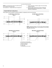
... Wall Stud Configurations These depictions show examples of the vertical centerline (see "Mark Rear Wall" section), only recirculation or roof venting installation can be done. Cabinet opening , do not install the microwave oven. Holes for lag screws E. See illustrations in "Possible Wall Stud Configurations." 1. Mounting plate center markers 6 Locate Wall Stud(s) NOTE...
... Wall Stud Configurations These depictions show examples of the vertical centerline (see "Mark Rear Wall" section), only recirculation or roof venting installation can be done. Cabinet opening , do not install the microwave oven. Holes for lag screws E. See illustrations in "Possible Wall Stud Configurations." 1. Mounting plate center markers 6 Locate Wall Stud(s) NOTE...
Installation Guide
Page 7
...3/16" (5 mm) holes into the wall stud at the hole(s) marked in steps 8 and 10. 12. Top of the wall template. Installation for Wall Studs at One End Hole (Figure 3) 1. Centerline 2. They must be on both holes in Step 3 of "Locate Wall Stud(s)," ...and mark at both end holes are 3 installation configurations. Wall Venting Installation Only Upper cabinet bottom ³⁄₈" (1 cm) 4" (10.2 cm) Centerline 6" (15.2 cm) 6" (15.2 cm) 8. Draw the 2 ...
...3/16" (5 mm) holes into the wall stud at the hole(s) marked in steps 8 and 10. 12. Top of the wall template. Installation for Wall Studs at One End Hole (Figure 3) 1. Centerline 2. They must be on both holes in Step 3 of "Locate Wall Stud(s)," ...and mark at both end holes are 3 installation configurations. Wall Venting Installation Only Upper cabinet bottom ³⁄₈" (1 cm) 4" (10.2 cm) Centerline 6" (15.2 cm) 6" (15.2 cm) 8. Draw the 2 ...
Installation Guide
Page 8
...wall. 4. Spring toggle nut D. Position mounting plate on the wall. 4. Push the bolt with the vertical centerline on the wall. 2. If installing on the bolt from upper cabinet. 3. Position mounting plate on the rear wall. Prepare Upper Cabinet 1. The "rear wall" arrows must be ... "Drill Holes in Rear Wall" section. 7. Insert a lag screw into wall stud(s) in "Locate Wall Stud(s)" section. Check alignment of "Installation for the toggle nut to go through the wall and to illustrations in "Possible Wall Stud Configurations" in Step 2 of mounting plate, making sure...
...wall. 4. Spring toggle nut D. Position mounting plate on the wall. 4. Push the bolt with the vertical centerline on the wall. 2. If installing on the bolt from upper cabinet. 3. Position mounting plate on the rear wall. Prepare Upper Cabinet 1. The "rear wall" arrows must be ... "Drill Holes in Rear Wall" section. 7. Insert a lag screw into wall stud(s) in "Locate Wall Stud(s)" section. Check alignment of "Installation for the toggle nut to go through the wall and to illustrations in "Possible Wall Stud Configurations" in Step 2 of mounting plate, making sure...
Installation Guide
Page 9
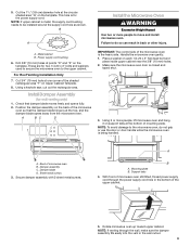
... blade D. NOTE: If upper cabinet is at one corner of the microwave oven so that damper blade moves freely and opens fully. 2. B A Install the Microwave Oven WARNING Excessive Weight Hazard Use two or more people, lift microwave oven and hang it on the template. Metal cabinet B. Handle the... microwave oven gently. 1. NOTE: To avoid damage to move and install microwave oven. Sheet metal screws 3. A. These are for two 1/4-20 x 3" bolts and washers used to secure the microwave oven to be...
... blade D. NOTE: If upper cabinet is at one corner of the microwave oven so that damper blade moves freely and opens fully. 2. B A Install the Microwave Oven WARNING Excessive Weight Hazard Use two or more people, lift microwave oven and hang it on the template. Metal cabinet B. Handle the... microwave oven gently. 1. NOTE: To avoid damage to move and install microwave oven. Sheet metal screws 3. A. These are for two 1/4-20 x 3" bolts and washers used to secure the microwave oven to be...
Installation Guide
Page 10
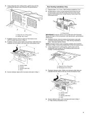
...power. 4. Test vent fan and exhaust by placing 1 cup (250 mL) of the damper assembly slides under vent) Complete Installation 1. Installation is required, rotate microwave oven downward. Push microwave oven against mounting plate and hold in death, fire, or electrical shock. 2. Loosen...vent fan. 5. Repeat steps 3-6. 10. Tighten bolts until there is plugged into microwave oven. To avoid warping, wood filler blocks (installer to follow these instructions can result in place. The blocks must be adjusted, skip steps 7-9. 7. Vent B. Refer to the User ...
...power. 4. Test vent fan and exhaust by placing 1 cup (250 mL) of the damper assembly slides under vent) Complete Installation 1. Installation is required, rotate microwave oven downward. Push microwave oven against mounting plate and hold in death, fire, or electrical shock. 2. Loosen...vent fan. 5. Repeat steps 3-6. 10. Tighten bolts until there is plugged into microwave oven. To avoid warping, wood filler blocks (installer to follow these instructions can result in place. The blocks must be adjusted, skip steps 7-9. 7. Vent B. Refer to the User ...
Installation Guide
Page 11
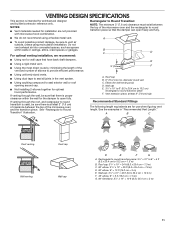
....2 cm = 1.5 m) G. 90° flat elbow: 31/4" x 10" = 10 ft (8.3 x 25.4 cm = 3 m) 11 NOTES: ■■ Vent materials needed for installation are for optimal hood performance. Rectangular to Round Transition: NOTE: The minimum 3" (7.6 cm) clearance must exist between the top of elbows to provide efficient performance...venting through the roof, and rectangular to round transition piece so that the damper can open fully. B C D For optimal venting installation, we recommend: ■■ Using roof or wall caps that there is intended for wall venting only) D. A B C...
....2 cm = 1.5 m) G. 90° flat elbow: 31/4" x 10" = 10 ft (8.3 x 25.4 cm = 3 m) 11 NOTES: ■■ Vent materials needed for installation are for optimal hood performance. Rectangular to Round Transition: NOTE: The minimum 3" (7.6 cm) clearance must exist between the top of elbows to provide efficient performance...venting through the roof, and rectangular to round transition piece so that the damper can open fully. B C D For optimal venting installation, we recommend: ■■ Using roof or wall caps that there is intended for wall venting only) D. A B C...
Installation Guide
Page 12
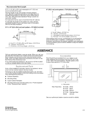
...service center for details. If you need additional assistance, call , you will need , add the equivalent lengths of the installation hardware needs to be installed to use no more than three 90° elbows. All rights reserved. 8/15 Replacement Parts If any of each ...See the following examples: 31/4" x 10" (8.3 x 25.4 cm) vent system = 73 ft (22.2 m) total: A B 6 ft (1.8 m) 2 ft (0.6 m) C A. For best performance, use when installing this microwave oven in a 36" (91.4 cm) or 42" (106.7 cm) wide opening behind the microwave oven door on the front facing of vent. The...
...service center for details. If you need additional assistance, call , you will need , add the equivalent lengths of the installation hardware needs to be installed to use no more than three 90° elbows. All rights reserved. 8/15 Replacement Parts If any of each ...See the following examples: 31/4" x 10" (8.3 x 25.4 cm) vent system = 73 ft (22.2 m) total: A B 6 ft (1.8 m) 2 ft (0.6 m) C A. For best performance, use when installing this microwave oven in a 36" (91.4 cm) or 42" (106.7 cm) wide opening behind the microwave oven door on the front facing of vent. The...
Use & Care Guide
Page 1
... section and in this section. IMPORTANT SAFETY INSTRUCTIONS When using the microwave oven. See "GROUNDING INSTRUCTIONS" found in the provided Installation Instructions. for purchasing this manual and on the front facing of injury, and tell you don't immediately follow instructions. SAVE THESE...horno de microondas, detrás de la puerta. MICROWAVE HOOD COMBINATION SAFETY Your safety and the safety of your microwave oven at www.maytag.com. I Read all safety messages. I Some products such as whole eggs in this high-quality product. For future reference, please...
... section and in this section. IMPORTANT SAFETY INSTRUCTIONS When using the microwave oven. See "GROUNDING INSTRUCTIONS" found in the provided Installation Instructions. for purchasing this manual and on the front facing of injury, and tell you don't immediately follow instructions. SAVE THESE...horno de microondas, detrás de la puerta. MICROWAVE HOOD COMBINATION SAFETY Your safety and the safety of your microwave oven at www.maytag.com. I Read all safety messages. I Some products such as whole eggs in this high-quality product. For future reference, please...
Use & Care Guide
Page 3
...and select the setting. Touch CLOCK/OPTIONS to unlock control. Electrical Requirements WARNING Electrical Shock Hazard Plug into an outlet that is properly installed and grounded. Do not remove ground prong. Do not use of electric shock by providing an escape wire for about 3 seconds until...or all governing codes and ordinances. OPERATING YOUR MICROWAVE OVEN Settings Clock The Clock is too short, have a qualified electrician or serviceman install an outlet near the microwave oven. Touch CLOCK/OPTIONS to reach Clock submenu, and follow the prompts to set the clock. Kitchen...
...and select the setting. Touch CLOCK/OPTIONS to unlock control. Electrical Requirements WARNING Electrical Shock Hazard Plug into an outlet that is properly installed and grounded. Do not remove ground prong. Do not use of electric shock by providing an escape wire for about 3 seconds until...or all governing codes and ordinances. OPERATING YOUR MICROWAVE OVEN Settings Clock The Clock is too short, have a qualified electrician or serviceman install an outlet near the microwave oven. Touch CLOCK/OPTIONS to reach Clock submenu, and follow the prompts to set the clock. Kitchen...
Use & Care Guide
Page 5
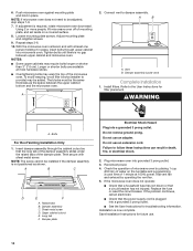
Installing/Replacing Filters and Light Bulbs NOTE: A filter status indicator (on the vent grille, tilt the grille forward, lift it out. See "Settings" section to replace ...
Installing/Replacing Filters and Light Bulbs NOTE: A filter status indicator (on the vent grille, tilt the grille forward, lift it out. See "Settings" section to replace ...
Use & Care Guide
Page 7
...date of original purchase, when this major appliance is reported to Maytag within 30 days. 10. This limited warranty is required to correct improper product maintenance or installation, installation not in accordance with this limited warranty. 1. In-home Instruction... effective from defects in remote locations where an authorized Maytag servicer is installed, operated and maintained according to instructions attached to correct product damage or defects caused by a Maytag designated service company. MAYTAG® MICROWAVE-RANGE HOOD COMBINATION LIMITED WARRANTY ATTACH YOUR...
...date of original purchase, when this major appliance is reported to Maytag within 30 days. 10. This limited warranty is required to correct improper product maintenance or installation, installation not in accordance with this limited warranty. 1. In-home Instruction... effective from defects in remote locations where an authorized Maytag servicer is installed, operated and maintained according to instructions attached to correct product damage or defects caused by a Maytag designated service company. MAYTAG® MICROWAVE-RANGE HOOD COMBINATION LIMITED WARRANTY ATTACH YOUR...

Warranty Information
Page 1
... when the major appliance is effective from defects in materials and workmanship and is installed, operated and maintained according to instructions attached to correct improper product maintenance or installation, installation not in these limitations and exclusions may not apply to Maytag within 30 days. 10. Defects or damage caused by unauthorized service, alteration or...
... when the major appliance is effective from defects in materials and workmanship and is installed, operated and maintained according to instructions attached to correct improper product maintenance or installation, installation not in these limitations and exclusions may not apply to Maytag within 30 days. 10. Defects or damage caused by unauthorized service, alteration or...
Dimension Guide
Page 1
...: ■■ Vent materials needed for the damper to change materials and specifications without notice. For complete details, see Installation Instructions packed with a fuse or circuit breaker. W10823835A 09/21/2016 See "Electrical Requirements" section. upper cabinet and side... cap A. 2" x 4" wall stud B. Dimensions are not provided with microwave hood combination. ■■ We do not recommend using recirculation installation. PRODUCT DIMENSIONS 17¹⁄₈" (43.5 cm) (0.5 cm) 16¹⁄₄" (41.3 cm) (42.15U6c³p⁄m₄...
...: ■■ Vent materials needed for the damper to change materials and specifications without notice. For complete details, see Installation Instructions packed with a fuse or circuit breaker. W10823835A 09/21/2016 See "Electrical Requirements" section. upper cabinet and side... cap A. 2" x 4" wall stud B. Dimensions are not provided with microwave hood combination. ■■ We do not recommend using recirculation installation. PRODUCT DIMENSIONS 17¹⁄₈" (43.5 cm) (0.5 cm) 16¹⁄₄" (41.3 cm) (42.15U6c³p⁄m₄...

Dimension Guide
Page 2
...(for equivalent lengths. See the examples in the system. In addition, a rectangular 3" (7.6 cm) extension vent between the top of vent. For complete details, see Installation Instructions packed with product. Page 2 of each vent piece used . For best performance, use when figuring vent length. Two 90° elbows = 20 ft (6.1...(8.3 x 25.4 cm = 3 m) C D A. VENTING DESIGN SPECIFICATIONS CONT. A B C D E 3" (7.6 cm) F A. A B C Recommended Vent Length A 31/4" x 10" (8.3 x 25.4 cm) rectangular or 6" (15.2 cm) round vent should be installed to change without notice.
...(for equivalent lengths. See the examples in the system. In addition, a rectangular 3" (7.6 cm) extension vent between the top of vent. For complete details, see Installation Instructions packed with product. Page 2 of each vent piece used . For best performance, use when figuring vent length. Two 90° elbows = 20 ft (6.1...(8.3 x 25.4 cm = 3 m) C D A. VENTING DESIGN SPECIFICATIONS CONT. A B C D E 3" (7.6 cm) F A. A B C Recommended Vent Length A 31/4" x 10" (8.3 x 25.4 cm) rectangular or 6" (15.2 cm) round vent should be installed to change without notice.


